Takeuchi compact excavator TB125, TB135, TB145 / diesel TNE / diesel Yanmar. Service Manual - page 30
 

  Index      Manuals     Takeuchi compact excavator TB125 (12510003~), TB135 (13510004~), TB145 (14510004~) / diesel TNE / diesel Yanmar. Service Manual


Search            copyright infringement  


Content      ..     28      29      30      31     ..


Takeuchi compact excavator TB125, TB135, TB145 / diesel TNE / diesel Yanmar. Service Manual - page 30


IV-168-10

HYDRAULIC UNITS

TRAVEL MOTOR

TB125, 135, 145

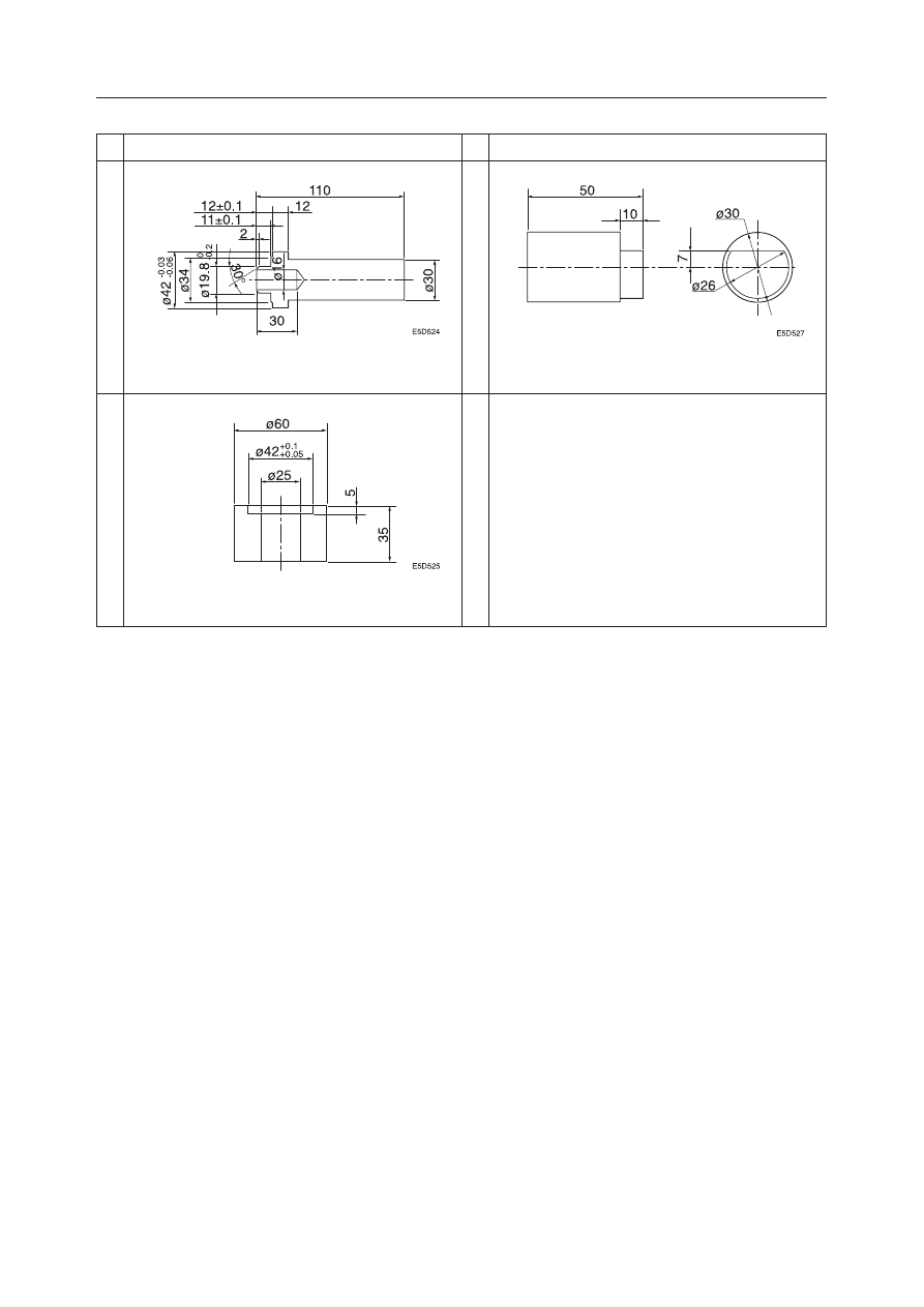
PRESSURE FITTING JIG (H)

NAME, DIMENSIONS

PRESSURE FITTING JIG ( I )

NAME, DIMENSIONS

INSTALLATION JIG (K)

9

10

11

Unit: mm

IV-168-11

HYDRAULIC UNITS

TRAVEL MOTOR

TB125, 135, 145

General Cautions

• Carry out disassembly and assembly operations in

a clean place and provide clean containers to place
the disassembled parts in.

• Before disassembly, clean around the ports and

remove the paint from each joint using a wire
brush.

• Wash the disassembled parts and dry them with

compressed air. Do not use a rag, as this could
cause clogging of dirt.

• Make match marks on each part so that they will be

assembled in the same positions when reassembled.

• Replace all seals with new ones each time the unit

is disassembled, coating them lightly with grease.

• Check each part to make sure there is no abnormal

wear or seizing and use sandpaper, etc. to remove
any burrs, sharp edges, etc.

Disassembly

Anti-Cavitation Valve

1. Take out the cap screws and the anti-cavitation

valve.

2. Take out the plug (1), then remove the spring (2),

the spring seat (3) and the spool (4).

Counterbalance Valve, 2-speed Control Valve

1. Take out the cap (1), then remove the spring (2),

the spring seat (3) and the spool assembly (4).
• Remove the spool assembly while turning it

gently.

• Be careful not to scratch or bruise the outside

surface.

IV-168-12

HYDRAULIC UNITS

TRAVEL MOTOR

TB125, 135, 145

2. Disassemble the spool assembly (4).

• Do not disassemble the spool assembly unless

it is absolutely necessary.
a. Take out the plug (5).

• Insert a ø5 

×

  30 mm pin (6) in the ø6

through hole in the spool, then fasten the
pin (6) by both ends in a vise and fasten
the spool assembly.

b. Remove the spring (7) and check valve (8).

• Be sure to keep the parts of the spool

assembly so that the left-right combina-
tion of the check valve (8) with respect to
the spool is kept the same when they are
assembled.

3. Remove the plug (9), then remove the spring seat

(10), the spring (11), the spool (12) and the spool
(13).
• Do not scratch or bruise the outside surface of

the spool.

4. Take out the cap screws.

• Evenly loosen them, as the valve body may be

lifted by the force exerted by the spring on the
brake piston.

IV-168-13

HYDRAULIC UNITS

TRAVEL MOTOR

TB125, 135, 145

5. Remove the valve body.

• Be careful not to let cylinder block come out.
• If it is difficult to remove, tap on it gently in the

removal direction using a plastic hammer or
pry it gently with a screw driver.

Hydraulic Motor, Reduction Gears

1. Remove the pins (1), (2) and the valve plate (3).

2. Remove the O-rings (4), (5).

3. Remove the springs (6) the brake piston (7).

• Blow compressed air into the parking brake

release port (A) of the flange holder and re-
move the brake piston.

4. Remove the cylinder block assembly, then disas-

semble the cylinder block assembly.

a. Remove the shoe holder (16), the piston as-

sembly (17), guide (18), the pin (19) and the
disc (20) from the cylinder block (21).
• Be careful not to scratch the sliding surfaces

of the cylinder block.

WARNING

Wear required appropriate equipment such as
safety glasses and filter mask when using  com-
pressed air, as metal fragments or other objects
can fly and cause serious personal injury.

Watch for parts that may spring out. Wear protec-
tive gear such as goggles.

WARNING

IV-168-14

HYDRAULIC UNITS

TRAVEL MOTOR

TB125, 135, 145

b. Remove the snap ring (22).
c. Remove the retainer (23), spring (24) and

retainer (25) from the cylinder block (21).
• Do not scratch the sliding surfaces of the

cylinder block.

5. Remove the swash plate (26), ball (27), piston

assembly (28) and spring (29) from the flange
holder.

6. Remove the cover (30).

a. Take out the plug, then set eye bolts (31) in the

threaded holes, pass a round bar through the
eye bolts and turn the cover (30) until the wire
(32) can be seen.

b. While pulling on the end of the wire (32) with

pliers, turn the cover (30) and pull the wire (32)
out.

c. Remove the cover (30) by hooking a hook in

the eye bolt (31) or using the round bar.

7. Remove the thrust plate (33), the gear S2 (34), the

carrier assembly (35) and the gear S1(36).

8. Remove the gear B2 (37), the needle (38) and the

inner race (39) from the carrier.

IV-168-15

HYDRAULIC UNITS

TRAVEL MOTOR

TB125, 135, 145

9. Remove the screw, then remove the thrust plate

(40).
• Heat the screws with a heat gun or the like to

soften the Loctite applied on the screw.

10. Remove gear B1 (41), the needle (42), inner race

(43) and thrust washer (44).
• Do not scratch the gear tooth surfaces or the

rotating surface of the collar.

11. Remove the plug.

12. Take out the balls.

a. After degreasing with paint thinner, white gaso-

line or similar cleaning oil, blow with air to
remove the balls.
• If the balls are difficult to remove, tap on the

outside of the housing with a hammer.

b. Insert a piece of piano wire through the bolt

hole to make sure that all the balls have been
removed.

13. Disassemble the flange holder and housing.

a. Insert a metal plate or removing jig (A) be-

tween the flange holder and housing.

b. Tighten with 3 cap screws (M12 

×

 1.75) which

are spaced equally apart.

IV-168-16

HYDRAULIC UNITS

TRAVEL MOTOR

TB125, 135, 145

14. Take out the plug.

15. Remove the ring nut.

• Use a tightening jig (B).

16. Remove the angular bearing (46) and remove the

floating seal (47).
• Place one end of a round bar against the steel

groove and tap the other end of the bar with a
hammer to remove the angular bearing (46).

17. Remove the floating seal (48).

IV-168-17

HYDRAULIC UNITS

TRAVEL MOTOR

TB125, 135, 145

18. Remove the shaft, then remove the oil seal.

• Bring a round bar in contact with the round

hole of the shaft and tap lightly with a hammer.

• Use a (–) screw driver to remove the oil seal.

19. Remove the bearing (49) from the shaft (50).

• Use removing jig (C).

IV-168-18

HYDRAULIC UNITS

TRAVEL MOTOR

TB125, 135, 145

Assembly

Hydraulic Motor, Reduction Gears

1. Install the floating seal (48) in the flange holder.

a. Insert the floating seal (48) temporarily using

installation jig (E).
• Apply grease to the seal.

b. Install it using installation jig (F).

2. Install the angular bearing.

• Use pressure fitting jig (D).

3. Install the other floating seal (47) on the housing.

a. Insert the floating seal temporarily using in-

stallation jig (E).
• Apply grease to the seal.

b. Install it using installation jig (F).

4. Install the flange holder.

• Remove any foreign matter from the sliding

surface of the floating seal and apply gear oil to
it.

• Use pressure fitting jig (G).

E5D532

IV-168-19

HYDRAULIC UNITS

TRAVEL MOTOR

TB125, 135, 145

5. Tighten the ring nut to secure the angular bearing.

• Use tightening jig (B).

Ring Nut: 196 

±

9.8 N·m

6. Install the plug.

• The seal tape is unnecessary.

Plug: 14.7 

±

4.9 N·m

7. Stake the plug at 2 points with a punch.

8. Put in the balls (46).

E5D535

B

IV-168-20

HYDRAULIC UNITS

TRAVEL MOTOR

TB125, 135, 145

9. Install the plug.

• Seal tape should be wound around the threads

of the plug.

• Make sure the head of the plug is not sticking

out of the housing.

Plug: 7.8 

±

1.0 N·m

10. Install the thrust washer (44), gear B1 (41), the

inner race (43) and the needle (42).

11. Install the thrust plate (40), then install the screw.

• Apply Loctite #262 to the screw.
• When applying Loctite, degrease all the sur-

faces thoroughly and use a hardening accelera-
tor.

Screw: 6.1 

±

2.0 N·m

12. Install the snap ring on the gear S1 (36), then

install the gears S1 (36).

13. Install the carrier assembly.

a. Install the inner race (39), the needle (38) and

gear B2 (37) in the carrier (35).

b. Install the carrier (35) in the housing.
c. Install the gear S2 (34).

14. Install the thrust plate (33).

15. Fit the O-ring on the cover (30) and install it on the

housing.
• Align the U-groove in the plug’s hole position.

IV-168-21

HYDRAULIC UNITS

TRAVEL MOTOR

TB125, 135, 145

16. Install the wire (32).

a. Bend the wire (32) at a point approximately 6

mm from the front end, then insert it in the bolt
hole in the housing.

b. Turn the cover and wind the wire (32) around

it.
• Use the eye bolts and a round bar.

17. Install the plug.

• Wind seal tape around the threads of the plug.

Plug: 7.8 

±

1.0 N·m

18. Install the oil seal in the flange holder.

• Use pressure fitting jig (H).

19. Install the ball bearing (49) on the shaft (50).

• Use pressure fitting jig ( I ).

20. Install the shaft assembly in the flange.

• Use pressure fitting jig (J).

IV-168-22

HYDRAULIC UNITS

TRAVEL MOTOR

TB125, 135, 145

21. Put in the balls (27) and install the spring (29),

piston assembly (28) and swash plate (26).
• Apply hydraulic oil to the sliding surfaces of

the swash plate.

22. Assemble the cylinder block assembly.

a. Install the retainer (25), spring (24) and re-

tainer (23) in the cylinder block (21).

b. Install the snap ring (22).

• Use the installation jig (K).

c. Install the pin (19) in the cylinder block (21).

• Apply grease to the pin.

d. Install the guide (18), shoe holder (16), piston

assembly (17) and disc (20).
• Apply hydraulic oil to the hole in the cylin-

der block.

Watch for parts that may spring out. Wear protec-
tive gear such as goggles.

WARNING

IV-168-23

HYDRAULIC UNITS

TRAVEL MOTOR

TB125, 135, 145

23. Install the cylinder block assembly.

a. Install the shaft spline in the guide.

b. Push the cylinder block by hand, making sure

the spring is working.
• Apply hydraulic oil to the sliding surfaces

of the cylinder block.

• Make sure the port area on the cylinder

block is free from foreign matter.

24. Install the pins (1) on the flange holder.

25. Install the O-ring (4) and the O-rings (5) on the

flange holder.

26. Install the pin and stake it at 2 points.

IV-168-24

HYDRAULIC UNITS

TRAVEL MOTOR

TB125, 135, 145

27. Install the valve plate (3) on the valve body.

• Apply grease to the bottom side of the valve

plate.

28. Install the pin on the flange holder.

29. Fit the O-rings (8), (9) on the brake piston (7).

30. Fit the backup rings (10), (11) on the brake piston

(7).

31. Install the brake piston (7) on the flange holder.

• Align the flange holder pin with the flange

holder pinhole.

• Install the brake piston by tapping around the

perimeter of it uniformly with a plastic ham-
mer.

32. Install the springs (6),  the O-ring (4) and  the

valve body.

33. Tighten the cap screws.

Cap Screw: 63.7 

±

4.9 N·m

IV-168-25

HYDRAULIC UNITS

TRAVEL MOTOR

TB125, 135, 145

34. Pour gear oil in through the plug hole, then install

the plug.
• Wind seal tape around the plug.
• Quantity of oil: Approx. 0.5 L

Plug: 39.2 

±

2 N·m

Counterbalance Valve, 2-speed Control Valve

1. Install the spool (13), the spool (12), the spring

(11) and the spring seat (10).
• Install the spool while turning it, making sure

it doesn’t get caught.

• Apply hydraulic oil to the spool.

2. Fit an O-ring on the plug (9), then install it in the

valve body.

Plug: 53.9 

±

4.9 N·m

3. Assemble the spool assembly.

a. Install the check valve (8) and spring (7) on the

spool.

b. Fit the O-ring on the plug (5), then install it in

the spool.

Plug: 31.9 

±

2.5 N·m

4. Install the spool assembly (4) in the valve body.

• Install the spool assembly while turning it,

making sure it doesn’t get caught.

• Apply hydraulic oil to the spool assembly.

5. Install the spring seat (3) and spring (2).

6. Fit the O-ring on the plug (1), then install the

valve body.

Plug: 240 

±

5 N·m


Content      ..     28      29      30      31     ..