Takeuchi compact excavator TB125, TB135, TB145 / diesel TNE / diesel Yanmar. Service Manual - page 29
 

  Index      Manuals     Takeuchi compact excavator TB125 (12510003~), TB135 (13510004~), TB145 (14510004~) / diesel TNE / diesel Yanmar. Service Manual


Search            copyright infringement  


Content      ..     27      28      29      30     ..


Takeuchi compact excavator TB125, TB135, TB145 / diesel TNE / diesel Yanmar. Service Manual - page 29


IV-162

HYDRAULIC UNITS

TRAVEL MOTOR

TB125, 135, 145

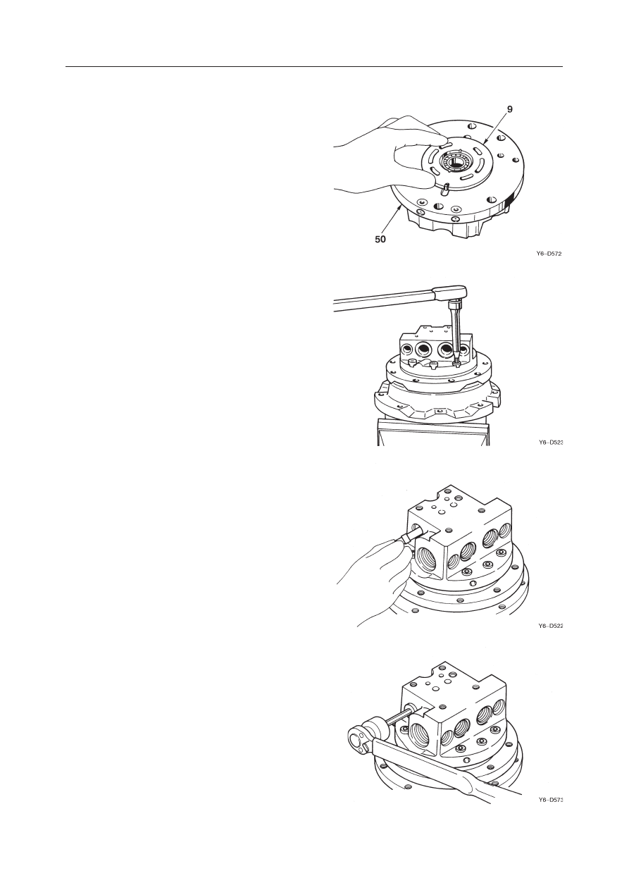
28. Install the valve plate (9) and O-ring on the valve

body (50).
• Apply grease to the bottom side of the valve

plate (9).

29. Set the valve body, then tighten the cap screw.

• Cap screw tightening torque:

63.7 

±

4.9 N·m (6.5 

±

0.5 kgf·m)

30. Set the spring on the spool, then install it the valve

body.
• Install the spool while turning it, making sure

it doesn’t get caught.

• Apply hydraulic oil to the spool.

31. Fit an O-ring on the plug, then install it in the

valve body.
• Plug tightening torque:

53.9 

±

4.9 N·m (5.5 

±

0.5 kgf·m)

IV-163

HYDRAULIC UNITS

TRAVEL MOTOR

TB125, 135, 145

32. Assemble the spool assembly.

a. Install the check valve and spring on the spool

(8).

b. Fit the O-ring on the plug, then install it in the

spool.
• Plug tightening torque:

31.9 

±

2.5 N·m (3.25 

±

0.25 kgf·m)

33. Install the spool assembly in the valve body.

• Install the spool assembly while turning it,

making sure it doesn’t get caught.

• Apply hydraulic oil to the spool assembly.

34. Install the spring seat and spring.

35. Fit the O-ring on the cap, then install the valve

body.
• Tightening torque:

240 

±

5 N·m (24.5 

±

0.5 kgf·m)

8

E5D537

IV-164

HYDRAULIC UNITS

TRAVEL MOTOR

TB125, 135, 145

36. Install the O-ring in the plate, then install the plate

on the valve body.
• Cap screw tightening torque:

29.4 

±

2.0 N·m (3.0 

±

0.2 kgf·m)

37. Fit the O-ring on the plug (2), then install the plug

in the valve body.
• Plug tightening torque:

34.3 

±

4.9 N·m (3.5 

±

0.5 kgf·m)

38. Pour gear oil in through the plug hole, then install

the plug (51).
• Wind seal tape around the plug.
• Quantity of oil: Approx. 0.5 L
• Plug tightening torque:

34.3 

±

4.9 N·m (3.5 

±

0.5 kgf·m)

E5D529

E5D538

IV-165

HYDRAULIC UNITS

TRAVEL MOTOR

TB125, 135, 145

Parts

INSPECTION AND ADJUSTMENT

Checking the Parts

There should be no abnormal scratches,
wear or seizing.

Floating Seal

Sliding Surface

Replace

Area Checked

Judgement Criteria

Treatment

There should be no abnormal scratches,
wear, flaking, etc. in the ball or race.

Sliding Surface

Surface  of  Gear  Teeth

There should be no abnormal scratches,

wear or flaking of the tooth surfaces (if
there has been pitting which covers 5%
or more of the engagement portion of
the tooth surface).
There should be no abnormal scratches,
wear or flaking of the rotating surface.

Front of cage and roller ro-
tating surface.

There should be no abnormal scratches,
wear or flaking of the rotating surface.

Surface condition of inner
race rotating surface.

There should be no abnormal scratches,
wear or flaking.

Surface of needle.

There should be no abnormal scratches,
wear or seizing.

Front of sliding surface

There should be no abnormal scratches,
wear or flaking in the tooth surfaces (if
there has been pitting which covers 5%
or more of the engagement portion of
the tooth surface).

Front of Gear Tooth Sur-
faces

There should be no abnormal scratches
(0.02 mm or greater), wear or seizing,
etc.

Front of sliding surface.

There should be no scratches or abnor-
mal wear.

Surface of oil seal.

There should be no abnormal scratches,
wear or flaking in the ball and race.

Front of sliding surface.

There should be no abnormal scratches
(0.02 mm or greater), wear or seizing.

0.04 mm or greater

Front of the surface which
slides with the sliding sur-
face of the piston assembly.
Clearance with the piston
assembly.

There should be no abnormal scratches
(0.02 mm or greater), wear or seizing.

Front of the surface which
slides with the valve plate.

0.04 mm or greater

Clearance with cylinder
block
Front of the surface which
slides with the swash plate.

There should be no abnormal scratches
(0.02 mm or greater), wear or seizing.
0.4 mm or greater

Clearance between piston
and shoe.

Angular Bearing

Planetary Gears

Inner Race

Needle

Thrust Washer

Housing, Sun Gear,
Drive Gear

Thrust Plate

O-ring
Shaft

Ball Bearing

Oil Seal
Swash Plate

Cylinder Block

Piston Assembly

Replace

Replace

Replace

Replace

Replace

Replace

Replace

Replace
Replace

Replace

Replace
Repair by lapping
(#1000) or replace.

Repair with wrap
(#1000) or replace
the cylinder block
and piston assem-
bly at the same
time.

Replace

IV-166

HYDRAULIC UNITS

TRAVEL MOTOR

TB125, 135, 145

Parts

Area Checked

Judgement Criteria

Treatment

Repair by lapping
(#1000) or replace.

Valve Plate

Front of the surface which
slides with the spool.

There should be no abnormal scratches
(0.02 mm or greater), wear or seizing.

Front of the surface which
slides with the spool.

There should be no abnormal scratches,
wear or seizing.
There should be no abnormal scratches,
wear or seizing.

Front of the surface which
slides with the base plate.

There should be no abnormal scratches,
wear or seizing.

Front of the surface which
slides with the check valve.

There should be no abnormal scratches,
wear or seizing.

Front of the surface which
slides with the spool.

There should be contact with the seat
around the entire circumference.

Surface of spool and seat.

Base Plate

Spool

Check Valve

Replace the base
plate and the spool
at the same time.

Replace the spool
and the check
valve at the same
time.

IV-167

HYDRAULIC UNITS

TRAVEL MOTOR

TB125, 135, 145

• Repair or replace the damaged piping.
• Remove the foreign matter and repair

or replace the damaged parts.

• Clean it.

TROUBLESHOOTING

Hydraulic Motor

Symptom

Does not move.

• Equipment other than the motor, coun-

terbalance valve or speed reducer is
malfunctioning.

• Check if the proper pressure is reached

on the motor inlet port side, then check
each device and repair if necessary.

Probable Causes

Remedy

• Replace the abnormally worn parts.

• Replace the damaged parts.

• Hydraulic oil is escaping due to ab-

normal wear of motor sliding parts.

• Principal motor parts are malfunc-

tioning due to damage.

• The proper volume of hydraulic oil is

not being supplied to the motor due to
the hydraulic pump, control valve,
etc.

• Check if the proper pressure is reached

on the motor inlet port side, then check
each device and repair if necessary.

• The motor’s volumetric efficiency is

dropping.

• Check if the sliding parts are abnor-

mally worn, then repair or replace the
worn parts.

• High pressure hydraulic oil is leaking

and flowing out of the drain port due
to wear of the motor's sliding parts.

• Bearings are worn.

• Replace the abnormally worn parts.

• Replace the bearings if they are abnor-

mally worn.

• Oil is leaking due damage to oil seals

or O-rings.

• Replace the oil seals and O-rings.

Motor won’t speed up.

Changes in rotational speed
are great.

Oil is leaking.

Counterbalance Valve

Symptom

Probable Causes

Remedy

Does not move or rotation is
slow.

Spool does not switch.
• No hydraulic oil is arriving.
• Foreign matter is caught.

• The orifice is clogged up.
The spool won’t return.
• Foreign matter gets caught.

• A spring is missing.
• A spring is damaged.
• The orifice is clogged up.

• Remove the foreign matter and repair

or replace the damaged parts.

• Install the spring.
• Replace the spring.
• Clean it.

Spool return is fast.
• The spring seat is missing.

• Install the spring seat.

The spool does not return.
• Foreign matter gets caught.

• A spring is damaged.
• The orifice is clogged up.

• Remove the foreign matter and repair

or replace the damaged parts.

• Replace the spring.
• Clean it.

Won’t stop or stopping is
slow.

Shock is great when stopping.

Valve makes an abnormal
noise.

IV-168

HYDRAULIC UNITS

TRAVEL MOTOR

TB125, 135, 145

Symptom

Probable Causes

Remedy

• Remove the foreign matter and repair

or replace the damaged parts.

• Install the spring.
• Replace the spring.

2-speed Control Function

Machine veers during travel. Spool doesn’t switch over.

• Foreign matter is caught.

• A spring is missing.
• A spring is damaged.

IV-168-1

HYDRAULIC UNITS

TRAVEL MOTOR

TB125, 135, 145

  1. Retainer
  2. Ball
  3. Shaft
  4. Cylinder Block
  5. Valve Plate
  6. Piston
  7. Shoe
  8. Shoe Holder
  9. Guide
10. Swash Plate

TRAVEL MOTOR (TB125: S/N 12514526~)

CONSTRUCTION

Hydraulic Motor

11. Pin
12. Spring
13. Retainer
14. Bearing
15. Bearing
16. Spring
17. Brake Piston
18. Spring
19. Snap Ring
20. O-ring

21. O-ring
22. O-ring
23. O-ring
24. Friction Disc
25. 2-Speed Piston
26. Oil Seal
27. Pin
28. Pin
29. Backup Ring
30. Backup Ring

IV-168-2

HYDRAULIC UNITS

TRAVEL MOTOR

TB125, 135, 145

  1. Housing
  2. Cover
  3. Carrier 2
  4. Gear B1
  5. Gear B2
  6. Gear S1
  7. Gear S2

Reduction Gears

  8. Flange Holder
  9. Thrust Plate
10. Screw
11. Snap Ring
12. Inner Race
13. Needle
14. Needle

15. Floating Seal
16. O-ring
17. Bearing
18. Thrust Washer
19. Inner Race
20. Ring Nut
21. Plug

22. O-ring
23. Plug
24. Wire
25. Thrust Plate
26. Plug
27. Ball

IV-168-3

HYDRAULIC UNITS

TRAVEL MOTOR

TB125, 135, 145

  1. Valve Body
  2. Spool
  3. Spring Seat
  4. Spool
  5. Spring
  6. Spring
  7. Spool
  8. Spring Seat
  9. O-ring

Counterbalance Valve, 2-speed Control Valve

10. Plug
11. Plug
12. O-ring
13. Plug
14. Plug
15. Plug
16. O-ring
17. O-ring
18. Plug

19. O-ring
20. Orifice
21. Plug
22. Spool
23. Spring
24. Spring Seat
25. O-ring
26. O-ring
27. Plug

A: 2-Speed Control Valve
B: Counterbalance Valve
C: Anti-Cavitation Valve

IV-168-4

HYDRAULIC UNITS

TRAVEL MOTOR

TB125, 135, 145

OPERATION

Hydraulic Motor

9 pistons (2) are fitted in the cylinder block (1) and
there is a valve plate (3) with two half moon ports, B
and C in the end. Also, the cylinder block (1) rotates
freely and is joined to the shaft (4) via the spline. On
the other band, the swash plate (5) is fastened to the
housing.
When high pressure oil is introduced into port B, one
piston (2) makes contact and force F bears on the
swash plate (5).
F = P 

×

 A  P: Pressure  A: Piston Sectional Area

The force F which the piston (2) applies to the swash
plate (5) is divided into force F1, which pushes the
plate, and force F2, which rotates the cylinder block
(1). The total sum of the components in the direction
of rotation of the high pressure side piston generates
a rotational force in the cylinder block (1) and via the
spline, torque is transmitted to the shaft (4), turning it.
Conversely, if high pressure oil is introduced to port
C, rotation is the reverse of the above.

Counterbalance Valve

If high pressure oil is introduced to port P1, the oil
pushes the check valve (6) up. This causes oil to flow
through the motor port M1 and to flow into chamber
B of the pilot portion and fill it. When hydraulic oil
flows the motor from port M1 and acts to turn the
motor, even if oil returns from the motor and flows
into port M2, since the flow is cut off by the check
valve (6), the pressure at port P1 and in chamber B
rises. If the pressure in chamber B becomes higher
than the set valve of the spring (7), the spool (8) moves
to the left side and ports M2 and P2 open up, causing
the motor to turn.

If the motor’s turning becomes too fast, and the
amount of oil flowing out of port M2 is greater than
the amount of oil flowing into port M1, the pressure
in port P1 and chamber B drops. When the pressure in
chamber B drops below the set valve of the spring (7),
the spool (8) attempts to return to the right side. As a
result, since the resuming oil is constricted at portion
D, back pressure is generated at port M2 and the
motor’s turning is slowed.


E5D504

E5D505

IV-168-5

HYDRAULIC UNITS

TRAVEL MOTOR

TB125, 135, 145

When the motor is slowed, the pressure in port P1 and
chamber B rises again and the spool (8) moves to the
left side, eliminating the back pressure generated at
port M2. In this way, the motor is controlled so that it
rotates at a speed appropriate for the amount of oil
flowing into it.

If the high pressure hydraulic oil introduced into port
P1 is cut off, the pressure at ports P1 and P2 becomes
the same and the spool (8) returns to the neutral
position by spring force. For this reason, the oil in
chamber B is pushed out at port P1. At this time, the
flow of oil is restricted by the orifice (9) as it is
returning to port P1, so the spool (8) returns to the
neutral position slowly. In this way, the motor is
stopped while the shock during stopping is absorbed.

Anti-Cavitation Valve

When decelerating, the oil supply from the P1 port to
the M1 motor port is not sufficient, causing the M1
motor port to have negative pressure. When this
happens, oil is directed from the M2 motor port to the
M1 motor port, reducing possible cavitation.
Normally, the spool (2) is pushed to the left by the
pressure of the passage (1).

When a negative pressure is created in the M1 motor
port during deceleration, the pressure in the passage
(1) also decreases to move the spool (2) to the right.
This causes the oil in the M2 motor port to flow from
the orifice (3) of the counter valve through the pas-
sages (4) and (1) into the M1 motor port.
This supply of oil continues until the counterbalance
valve spool (5) cuts the flow from the path (1) to the
M1 motor port.

E5D506

IV-168-6

HYDRAULIC UNITS

TRAVEL MOTOR

TB125, 135, 145

Parking Brake

The cylinder block (1) and disc (2) are connected via
a spline.
The disc (2) is pushed against the flange holder (5) by
the force of the spring (3) via the brake piston (4) and
brake force is generated by the friction force between
the flange holder (5) and the brake piston (4) stopping
the cylinder block (1) from turning.

When hydraulic oil is introduced into the motor, the
spool (6) of the counterbalance valve moves out and
the parking brake release port (7) opens. Hydraulic oil
passes through this port and flows to the brake piston
chamber (8), overpowers the spring and moves the
brake piston (4) to the left. When this happens, the
disc (2) rotates freely between the flange holder (5)
and the brake piston (4), releasing the parking func-
tion.
Also, when the motor stops, the spool (6) returns to
the neutral position and the parking release port (7)
opens. Hydraulic oil in the brake piston chamber (8)
is introduced into the motor case and parking brake
force from the spring (3) acts.

2-Speed Mechanism

2-Speed Control Valve

If high pressure oil is introduced into port M1 and the
control valve is in the 1st speed position, the spool (1)
is moved to the left position by the spring (2) and the
swash plate control piston chambers (3) connect with
port T through the respective ports Pi1 and Pi2. For
this reason, no force acts on the swash plate to push it
up at the swash plate control position (11).

If the control valve is switched to the 2nd speed side
position, hydraulic oil is introduced from the port to
the spool (1) and the spool (1) switches to the right. As
a result, some of the high pressure oil flows to the
swash plate control piston chambers (3) through port
M1, port Pi1, port M2 and port Pi2, respectively,
moving the pistons.
When the engine stops, no hydraulic oil comes, so the
spool (1) returns to the 1st speed by the spring (2).

IV-168-7

HYDRAULIC UNITS

TRAVEL MOTOR

TB125, 135, 145

E5D512

6

9

C

5

3

10

11

A

7

B

8

β

α

Swash Plate

The swash plate (5) has 3 planes, A, B and C, as shown
in the figure, and it is assembled in such a way that its
angle of inclination in the flange holder (6) can varied
by two balls (7). When the 2-speed control valve is
switched to the 1st speed side, the swash plate control
piston chamber (3) is connected to tank port and the
swash plate (5) is stabilized at plane A, forming swash
plate angle  

α

, by the piston assembly (8) and the force

of the springs (9), (10), achieving 1st speed (low
speed) motor rotation.
When the 2-speed control valve is switched to 2nd
speed, the swash plate control piston chamber (3) is

connected to the motor drive pressure port and the
swash plate (5) stabilizes at plane B due to the equi-
librium between the force of the springs (9), (10) and
the force of the control piston (11), thus, assuming
swash plate angle 

β

. In this way, 2nd speed (High

speed) motor rotation is achieved.
When the engine is stopped, the pilot pressure of the
2-speed control valve is cut off, so the swash plate (5)
is stabilized at the swash plate a plane A by the force
of the springs (9), (10), changing to the 1st speed side.
For this reason, when starting, the motor also is in 1st
speed.

Automatic Switching to 2nd Speed

When the motor load is increased during the 2nd
speed, the motor is automatically switched to the 1st
speed position.
During the 2nd speed, the pilot pressure PS is led to
the pilot chamber (1) to provide force for pushing the
spool (2) to the right. The load pressure on the motor
Pin is led to the chamber (3) to provide force for
pushing the spool (2) to the left. When the motor is
lightly loaded and the pressure Pin is low, the spool
(2) is pushed to the right. The pressures M1 and M2
in the motor act on the swash plate control piston (4)
to push up the swash plate (5).
When the motor becomes heavily loaded and the load
pressure Pin is increased such that it exceeds the pilot
pressure Ps, the spool (2) is moved to the left.
The pressurized oil that has been acting on the swash
plate control piston (4) now flows through the orifices
(6) and (7) into the tank passage. The return oil also
flows through the orifices (6) and (7), which allows
the swash plate control piston (4) to return slowly to
change the motor to the 1st speed position.

IV-168-8

HYDRAULIC UNITS

TRAVEL MOTOR

TB125, 135, 145

Reduction Gears

The reduction gear has a simple planetary two-stage
configuration. It decelerates the high speed rotary
motions of the hydraulic motor, converts them into
low speed high torque, and rotates the case. The
output shaft of the hydraulic motor is connected to the
gear S2 via the spline. The rotation of the gear S2 is
decelerated by one stage among the gears S2, B2 and
a2. This one-stage decelerated rotation is further
decelerated by two stages among the gears S1, B1 and
a1 that are connected to the carrier 2 (1) via the spline.
This rotation is conveyed to the rotary main body via
the inner gears a1 and a2 as the driving force of the
motor.

C4D560

a1,a2

S2

1

S1

B1

B2

IV-168-9

HYDRAULIC UNITS

TRAVEL MOTOR

TB125, 135, 145

DISASSEMBLY AND ASSEMBLY

Table of Special Tools

NAME, DIMENSIONS

REMOVING JIG (A)

A: DIVIDED INTO 2 EQUAL PARTS

TIGHTENING JIG (B)

A: WELD

REMOVING JIG (C)

NAME, DIMENSIONS

PRESSURE FITTING JIG (D)

INSTALLATION JIG (E)

A: FINE CHAMFERING

INSTALLATION JIG (F)

A: R0.3 OR LESS

PRESSURE FITTING JIG (G)

1

2

3

4

5

6

7

8

Unit: mm

A: EYE BOLT JIS B 1168 M10
B: WELD

EYE BOLT


Content      ..     27      28      29      30     ..