Takeuchi compact excavator TB125, TB135, TB145 / diesel TNE / diesel Yanmar. Service Manual - page 27
 

  Index      Manuals     Takeuchi compact excavator TB125 (12510003~), TB135 (13510004~), TB145 (14510004~) / diesel TNE / diesel Yanmar. Service Manual


Search            copyright infringement  


Content      ..     25      26      27      28     ..


Takeuchi compact excavator TB125, TB135, TB145 / diesel TNE / diesel Yanmar. Service Manual - page 27


IV-130

HYDRAULIC UNITS

CYLINDERS

TB125, 135, 145

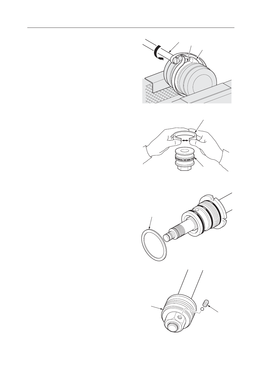
c. Since the slipper ring (29) is extended when it

is installed, correct it by the following proce-
dure.
(1) Set correction jigs (E) and (F) as shown in

the figure. The slipper ring should be posi-
tioned in the center of the band at this time.

(2) Tighten for 10 seconds or longer.

2. Install the wear ring (11).

• Spread the wear ring at the cut portion the

minimum amount necessary to install it in the
shaft direction.

Piston Rod Assembly

1. Fasten the piston rod in a horizontal position, then

assemble the rod cover assembly and lock washer
(3).

2. Install the piston unit.

a. Fit the shim and piston (2) and tighten them.

• Piston tightening torque:

980 N·m (100 kgf·m)

b. Insert the ball, tighten the set screw (1) and

stake at 2 points with a punch.
• Setscrew tightening torque:

16.2 N·m (1.65 kgf·m)

E

29

F

K3D410

E5D414

12

11

K3D408

3

K3D407

2

1

IV-131

HYDRAULIC UNITS

CYLINDERS

TB125, 135, 145

Cylinder Assembly

1. Fasten the tube in a horizontal position, then

insert the piston rod assembly in the tube.
• During insertion, align the center of the piston

rod with the center of the tube, inserting it
straight so that the seals will not be scratched.

2. Tighten the rod cover, then bend the lock washer

to prevent it from turning.
• When installing the rod cover, apply Three

Bond #1901 or a comparable product to the
threads.

• Rod cover tightening torque:

451 

±

104 N·m (46 

±

10.6 kgf·m)

INSPECTION AND ADJUSTMENT

“IV-117~118”

TROUBLESHOOTING

“IV-119”

IV-132

HYDRAULIC UNITS

CYLINDERS

TB125, 135, 145

TABLE OF SPECIAL TOOLS

MATERIAL: SS41

MATERIAL: SS41

Installation Jig (A)

Installation Jig (B)

Installation Jig (A)

Installation Jig (B)

A

B

C

D

E

F

A

B

C

D

E

F

47.5

44.9

10.0

45.0

10.0

50.0

54.5

44.8

10.0

5.0

30.0

70.0

Fitting Jig (D)

Sliding Jig (C)

MATERIAL: RESIN

MATERIAL: RESIN

Sliding Jig (C)

Fitting Jig (D)

A

B

C

D

E

79.5

20.0

25.0

65.0

49.0

A

B

C

D

E

F

G

H

80.0

1.0

7.0

80.0

3.5

3.5

60.0

82.0

Unit: mm

Unit: mm

IV-133

HYDRAULIC UNITS

CYLINDERS

TB125, 135, 145

Corrective Jig (F)

Corrective Jig (E)

A: 15 mm
B: METAL BAR
C: POLYESTER BAND WITH CANVAS
D: BAND INSTALLATION SLOT

MATERIAL: ACRYL RESIN

Corrective Jig (F)

A

B

C

D

E

20

45

40

15

30

Unit: mm

K3D414

15

RA

RB

RC

E

D

IV-134

HYDRAULIC UNITS

CYLINDERS

TB125, 135, 145

IV-135

HYDRAULIC UNITS

CYLINDERS

TB125, 135, 145

TENSIONING CYLINDER

CONSTRUCTION

  1. Tube
  2. Piston Rod
  3. Rod Cover
  4. Bushing
  5. Dust Seal
  6. Snap ring
  7. O-ring

  8. Piston
  9. Wear Ring
10. Rod Packing
11. Backup Ring
12. O-ring
13. Backup Ring
14. O-ring

15. Set Screw
16. Ball
17. Valve Set
18. Handle
19. Valve Set

K3D420

6

5

7

4

3

1

2

8

13

12

14

9

11

10

15

16

18

17

19

IV-136

HYDRAULIC UNITS

CYLINDERS

TB125, 135, 145

DISASSEMBLY AND ASSEMBLY

Table of Special Tool

General Cautions

“IV-102”

Following is an explanation of the tensioning cylinder
disassembly procedure. Follow the procedure used to
disassemble the tensioning cylinder in reverse order
when assembling it.

Disassembly

Cylinder Assembly

1. Fasten the tube so that it is flat.

2. Drain out hydraulic oil remaining in the cylinder.

• Move the piston rod gently to prevent the

hydraulic oil from spraying out and scattering
all over.

3. Free the locked portion of the rod cover.

• Since the lock is integrated with the cylinder

tube, be careful not to bend it or to scratch it
when the lock is being freed.

4. Loosen the rod cover.

• Measures should be taken to prevent the piston

rod from being hit.

• Rod cover tightening torque:

333 N·m (34 kgf·m)

5. Take the piston rod assembly out or the tube.

• Pull it out straight to prevent the sliding sur-

faces from being scratched.

Names, Dimensions

Unit: mm

Installation Jig (A)

MATERIAL: SS41

IV-137

HYDRAULIC UNITS

CYLINDERS

TB125, 135, 145

Piston Rod Assembly

1. Fasten the piston rod assembly securely in a level

position.

2. Remove the piston.

a. Take out the set screw (1) and remove the ball

(2).
• The set screw is staked at 2 places with a

punch, so grind off the staked portions using
a hand drill.

• When assembling, caulk the set screw at

two places with a punch.

• Set screw tightening torque:

16.7 N·m (1.7 kgf·m)

b. Loosen piston (3) and remove it.

• Piston tightening torque:

784 N·m (80 kgf·m)

c. Remove the O-ring (4) from the piston rod.

3. Remove the rod cover (5).

Piston

1. Remove the wear ring (6) from the piston.

• Spread the wear ring the minimum amount

necessary and remove it in the axial direction.

2. Remove the O-ring (7) and backup ring (8).

• When assembling, be careful to install in the

proper position.

3. Remove the rod packing (9) and backup ring (10).

• When assembling, be careful to install the rod

packing in the proper position.

IV-138

HYDRAULIC UNITS

CYLINDERS

TB125, 135, 145

Rod Cover

1. Remove the O-ring (11).

2. Remove the Snap ring (12) and the dust seal (13).

3. Remove the bushing.

• Since the bushing has been pressure fitted

tightly in the rod cover, it is impossible to take
it out. First use a lathe to grind down the inside
portion until only a thin piece remains, then
insert a copper spatula strongly and pry it out
to removed it.

• When assembling, use installation jig (A) and

pressure fit the bushing with a press.

• When assembling, apply hydraulic oil to the

inside surface of the rod cover before installing
it.

• After installation, make sure there are no level

differences with the bushing.

INSPECTION AND ADJUSTMENT

“IV-117~118”

TROUBLESHOOTING

“IV-119”

IV-139

HYDRAULIC UNITS

TRAVEL MOTOR

TB125, 135, 145

  1. Retainer
  2. Ball
  3. Shaft
  4. Cylinder Block
  5. Valve Plate
  6. Piston
  7. Shoe
  8. Shoe Holder
  9. Guide
10. Swash Plate

TRAVEL MOTOR (TB125: S/N 12510009~12514525)

CONSTRUCTION

Hydraulic Motor

11. Pin
12. Spring
13. Retainer
14. Bearing
15. Bearing
16. Spring
17. Brake Piston
18. Spring
19. Snap Ring
20. O-ring

21. O-ring
22. O-ring
23. O-ring
24. Friction Disc
25. 2-Speed Piston
26. Oil Seal
27. Pin
28. Pin

E5D500

26

2

16

25

14

10

7

8

6

24

22

21

20

18

5

15

9

3

11

13

17

4

12

23

27

1

19

28

IV-140

HYDRAULIC UNITS

TRAVEL MOTOR

TB125, 135, 145

  1. Housing
  2. Cover
  3. Carrier 2
  4. Gear B1
  5. Gear B2
  6. Gear S1
  7. Gear S2

Reduction Gears

  8. Flange Holder
  9. Thrust Plate
10. Screw
11. Snap Ring
12. Inner Race
13. Needle
14. Needle

15. Floating Seal
16. O-ring
17. Bearing
18. Thrust Washer
19. Inner Race
20. Ring Nut
21. Plug

22. O-ring
23. Plug
24. Wire
25. Thrust Plate
26. Plug
27. Plug
28. Ball

E5D501

21

22

7

16

23

24

25

5

14

19

3

26

27

2

11

6

10

9

4

13

12

18

20

28

17

15

1

8

IV-141

HYDRAULIC UNITS

TRAVEL MOTOR

TB125, 135, 145

  1. Valve Body
  2. Spool
  3. Check Valve
  4. Spring Seat
  5. Spool
  6. Spring
  7. Spring
  8. Spring
  9. Plug
10. Plug
11. Orifice
12. Ring
13. Plug

Counterbalance Valve, 2-speed Control Valve

14. Plug
15. O-ring
16. O-ring
17. O-ring
18. Orifice
19. Plug
20. Orifice
21. Washer
22. O-ring
23. Filter
24. Plate
25. O-ring

A: 2-Speed Control Valve
B: Counterbalance Valve

E5D502

24

25

22

A

B

  11

2

1

3

6

12

7

16

15

4

9

14

5

19

18

8

17

10

13

20

21

23

IV-142

HYDRAULIC UNITS

TRAVEL MOTOR

TB125, 135, 145

OPERATION

Hydraulic Motor

9 pistons (2) are fitted in the cylinder block (1) and
there is a valve plate (3) with two half moon ports, B
and C in the end. Also, the cylinder block (1) rotates
freely and is joined to the shaft (4) via the spline. On
the other band, the swash plate (5) is fastened to the
housing.
When high pressure oil is introduced into port B, one
piston (2) makes contact and force F bears on the
swash plate (5).
F = P 

×

 A  P: Pressure  A: Piston Sectional Area

The force F which the piston (2) applies to the swash
plate (5) is divided into force F1, which pushes the
plate, and force F2, which rotates the cylinder block
(1). The total sum of the components in the direction
of rotation of the high pressure side piston generates
a rotational force in the cylinder block (1) and via the
spline, torque is transmitted to the shaft (4), turning it.
Conversely, if high pressure oil is introduced to port
C, rotation is the reverse of the above.

Counterbalance Valve

If high pressure oil is introduced to port P1, the oil
pushes the check valve (6) up. This causes oil to flow
through the motor port M1 and to flow into chamber
B of the pilot portion and fill it. When hydraulic oil
flows the motor from port M1 and acts to turn the
motor, even if oil returns from the motor and flows
into port M2, since the flow is cut off by the check
valve (6), the pressure at port P1 and in chamber B
rises. If the pressure in chamber B becomes higher
than the set valve of the spring (7), the spool (8) moves
to the left side and ports M2 and P2 open up, causing
the motor to turn.

If the motor’s turning becomes too fast, and the
amount of oil flowing out of port M2 is greater than
the amount of oil flowing into port M1, the pressure
in port P1 and chamber B drops. When the pressure in
chamber B drops below the set valve of the spring (7),
the spool (8) attempts to return to the right side. As a
result, since the resuming oil is constricted at portion
D, back pressure is generated at port M2 and the
motor’s turning is slowed.


E5D504

E5D505

IV-143

HYDRAULIC UNITS

TRAVEL MOTOR

TB125, 135, 145

When the motor is slowed, the pressure in port P1 and
chamber B rises again and the spool (8) moves to the
left side, eliminating the back pressure generated at
port M2. In this way, the motor is controlled so that it
rotates at a speed appropriate for the amount of oil
flowing into it.

If the high pressure hydraulic oil introduced into port
P1 is cut off, the pressure at ports P1 and P2 becomes
the same and the spool (8) returns to the neutral
position by spring force. For this reason, the oil in
chamber B is pushed out at port P1. At this time, the
flow of oil is restricted by the orifice (9) as it is
returning to port P1, so the spool (8) returns to the
neutral position slowly. In this way, the motor is
stopped while the shock during stopping is absorbed.

Parking Brake

The cylinder block (1) and disc (2) are connected via
a spline.
The disc (2) is pushed against the flange holder (5) by
the force of the spring (3) via the brake piston (4) and
brake force is generated by the friction force between
the flange holder (5) and the brake piston (4) stopping
the cylinder block (1) from turning.

When hydraulic oil is introduced into the motor, the
spool (6) of the counterbalance valve moves out and
the parking brake release port (7) opens. Hydraulic oil
passes through this port and flows to the brake piston
chamber (8), overpowers the spring and moves the
brake piston (4) to the left. When this happens, the
disc (2) rotates freely between the flange holder (5)
and the brake piston (4), releasing the parking func-
tion.
Also, when the motor stops, the spool (6) returns to
the neutral position and the parking release port (7)
opens. Hydraulic oil in the brake piston chamber (8)
is introduced into the motor case and parking brake
force from the spring (3) acts.

E5D506

IV-144

HYDRAULIC UNITS

TRAVEL MOTOR

TB125, 135, 145

2-Speed Mechanism

2-Speed Control Valve

If high pressure oil is introduced into port M1 and the
control valve is in the 1st speed position, the spool (1)
is moved to the left position by the spring (2) and the
swash plate control piston chambers (3) connect with
port T through the respective ports Pi1 and Pi2. For
this reason, no force acts on the swash plate to push it
up at the swash plate control position (11).

If the control valve is switched to the 2nd speed side
position, hydraulic oil is introduced from the port to
the spool (1) and the spool (1) switches to the right. As
a result, some of the high pressure oil flows to the
swash plate control piston chambers (3) through port
M1, port Pi1, port M2 and port Pi2, respectively,
moving the pistons.
When the engine stops, no hydraulic oil comes, so the
spool (1) returns to the 1st speed by the spring (2).

Swash Plate

The swash plate (5) has 3 planes, A, B and C, as shown
in the figure, and it is assembled in such a way that its
angle of inclination in the flange holder (6) can varied
by two balls (7). When the 2-speed control valve is
switched to the 1st speed side, the swash plate control
piston chamber (3) is connected to tank port and the
swash plate (5) is stabilized at plane A, forming swash
plate angle 

α

, by the piston assembly (8) and the force

of the springs (9), (10), achieving 1st speed (low
speed) motor rotation.
When the 2-speed control valve is switched to 2nd
speed, the swash plate control piston chamber (3) is

connected to the motor drive pressure port and the
swash plate (5) stabilizes at plane B due to the equi-
librium between the force of the springs (9), (10) and
the force of the control piston (11), thus, assuming
swash plate angle 

β

. In this way, 2nd speed (High

speed) motor rotation is achieved.
When the engine is stopped, the pilot pressure of the
2-speed control valve is cut off, so the swash plate (5)
is stabilized at the swash plate a plane A by the force
of the springs (9), (10), changing to the 1st speed side.
For this reason, when starting, the motor also is in 1st
speed.

E5D512

6

9

C

5

3

10

11

A

7

B

8

β

α

IV-145

HYDRAULIC UNITS

TRAVEL MOTOR

TB125, 135, 145

Reduction Gears

The reduction gear has a simple planetary two-stage
configuration. It decelerates the high speed rotary
motions of the hydraulic motor, converts them into
low speed high torque, and rotates the case. The
output shaft of the hydraulic motor is connected to the
gear S2 via the spline. The rotation of the gear S2 is
decelerated by one stage among the gears S2, B2 and
a2. This one-stage decelerated rotation is further
decelerated by two stages among the gears S1, B1 and
a1 that are connected to the carrier 2 (1) via the spline.
This rotation is conveyed to the rotary main body via
the inner gears a1 and a2 as the driving force of the
motor.

C4D560

a1,a2

S2

1

S1

B1

B2


Content      ..     25      26      27      28     ..