Takeuchi compact excavator TB125, TB135, TB145 / diesel TNE / diesel Yanmar. Service Manual - page 26
 

  Index      Manuals     Takeuchi compact excavator TB125 (12510003~), TB135 (13510004~), TB145 (14510004~) / diesel TNE / diesel Yanmar. Service Manual


Search            copyright infringement  


Content      ..     24      25      26      27     ..


Takeuchi compact excavator TB125, TB135, TB145 / diesel TNE / diesel Yanmar. Service Manual - page 26


IV-116

HYDRAULIC UNITS

CYLINDERS

TB125, 135, 145

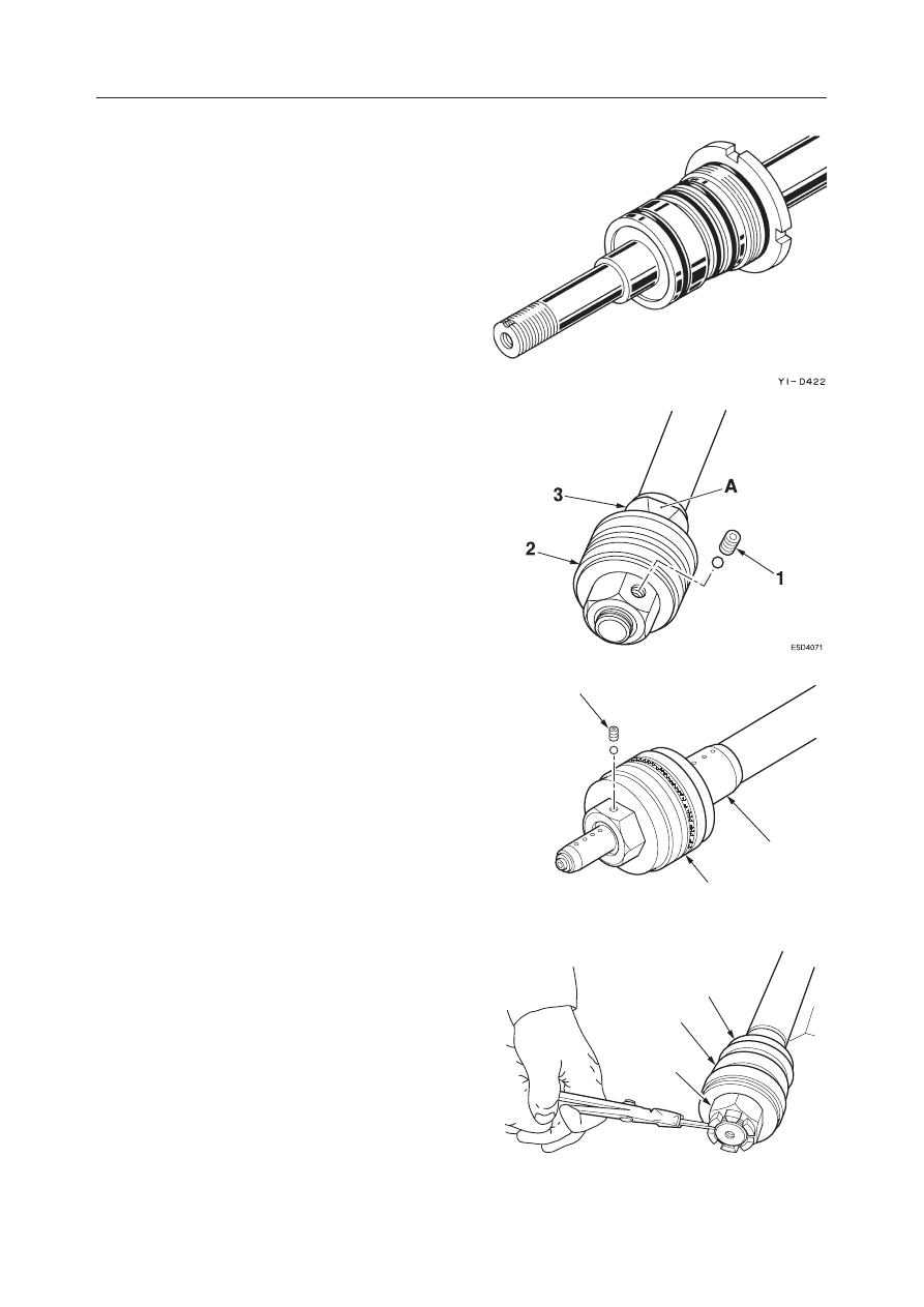
2. Install the rod cover assembly assembled in the

above step (1) on the piston rod.

3. Install the piston unit.

a. Install the spacer and cushion bearing (3).

• Be sure to set with the flat side (A) of the

cushion bearing in the proper direction.

• Piston tightening torque: Refer to the table

on the next page.

b. Insert the ball, tighten the set screw (1) and

stake at 2 points with a punch.
• Set screw tightening torque: Refer to the

table on the next page.

a. Install the packing holder (5) on the piston rod.
b. Install the O-ring and the piston (2) on the

piston rod.

c. Tighten the nut (4) and fix it with the split pin.

• Nut tightening torque: Refer to the table on

the next page.

E5D408

1

3

2

E5D409

2

4

5

IV-114

IV-117

HYDRAULIC UNITS

CYLINDERS

TB125, 135, 145

a. Install the cushion bearing (3) and the packing

holder (5) on the piston rod.

b. Install the O-ring and the piston (2) on the

piston rod, and then tighten the piston (2).
• Piston tightening torque: Refer to the table

below.

c. Lock with the set screw (1).

E5D410

5

2

1

3

E5D411

5

2

1

3

IV-115

IV-118

HYDRAULIC UNITS

CYLINDERS

TB125, 135, 145

Cylinder Assembly

1. Fasten the tube in a horizontal position, then

insert the piston rod assembly in the tube.
• During insertion, align the center of the piston

rod with the center of the tube, inserting it
straight so the seals will not be scratched.

2. Tighten the rod cover.

• Rod cover tightening torque

3. Bend the lock rib on the tube down in a notch of

the rod cover to lock it.

Model

Unit

Boom

Arm

Bucket

Dozer Blade

Swing

Telescopic Arm

Bucket (for Telescopic Arm)

N·m

TB125

TB135

TB145

N·m

N·m

324

304

402

490 (343**)

235

343

333

304

392

333

304

294

647 (735*)

588

539

853

588

304

: 14510004~14510788

∗∗

: 12510009~12514525

IV-116

IV-117

HYDRAULIC UNITS

CYLINDERS

TB125, 135, 145

INSPECTION AND ADJUSTMENT

Inspection after Disassembly

Clean each part thoroughly with cleaning oil, then
carry out the following checks. When a cylinder has
been disassembled, replace all the seals with new
ones.

1. Piston Rod

• Replace the rod if there are cracks.
• If the threads are damaged, repair them or

replace it.

• If the plating layer of the plated portion is

broken, rusted or scratched, replace it.

• If the rod is bent more than the limit of 1 mm

in 1 m, replace it. (Measure by the method
shown in the figure at right.
If the bending of the rod is within the above
limit, yet is bent a lot in a small distance so that
it won’t move smoothly, replace the rod if it
makes a squeaking sound in the operation test
after reassembly or if it catches during move-
ment.

• If the inner diameter of the clevis bushing is

worn, replace the bushing.

2. Tube

• If there are cracks in the welded portion, re-

place it.

• Replace the tube if the inside surface is scratched

or if it leaks hydraulic oil.

• If the inner diameter of the clevis bushing is

worn, replace the bushing.

3. Rod Cover

• If the bushing inner diameter is worn and the

clearance with the piston rod is greater than
0.25 mm, replace the bushing.

• If the inside surface of the bushing is scratched,

and the scratches are deeper than the depth of
the coating layer, replace the bushing.

Measuring the Bend

a. Support the portion of the rod with the same

diameter at both ends on V-blocks.

b. Set a dial gauge at the center between the two

blocks.

c. Rotate the rod and take a reading of the maxi-

mum and minimum runout indicated by the
dial gauge.

IV-118

HYDRAULIC UNITS

CYLINDERS

TB125, 135, 145

Inspection after Assembly

No Load Operation Test

1. Place the cylinder in a horizontal position with no

load.

2. Apply gentle pressure alternately to the ports at

both ends, operating the piston rod 5 or 6 times.

3. Make sure there is no abnormality in the operat-

ing condition.

Leak Test

External Leakage
1. Apply test pressure for 3 minutes each to the

retraction side and the extension side.

2. Make sure there are no abnormalities such as

external leakage or permanent deformation, etc.
in the rod seal, the rod cover mount, or in any
welded portion.

Internal Leakage
1. Disconnect the extension side hose.
2. Apply test pressure to the retraction side for 3

minutes.

3. Measure the amount of oil that has leaked from

the extension side.
• The amount of leakage should be 1 cm

3

 / 3min

or less.

Bleeding Air from the Hydraulic Cylinder

Bleed the air out of the cylinder when the cylinder is
removed or when the hydraulic piping, etc. is discon-
nected.
1. Start the engine and let it idle for approximately

5 minutes.

2. With the engine running at slow speed, extend

and retract the cylinder 4 or 5 times.
• Move the piston rod to a position 100 mm

before the end of the stroke, being careful not
to apply any relief at all.

3. With the engine at top speed, repeat the operation

in (2), then with the engine running at slow speed,
move the piston rod to the stroke end and apply
relief.

IV-119

HYDRAULIC UNITS

CYLINDERS

TB125, 135, 145

• Remove the foreign matter.

• Replace the affected parts.

TROUBLESHOOTING

Symptom

Probable Causes

Remedy

Oil leaks from piston rod
sliding surface (an oil ring
forms on the piston and
this enlarges and drips off).

• Foreign matter is caught in the inner

diameter portion of the rod packing,
backup ring or dust seal.

• The inner diameter lip of the rod packing,

backup ring or dust seal is damaged or
abnormal.

• Piston rod sliding  surface is scratched.

• The hardened chrome plating is separat-

ing from the piston rod.

• Smooth the sliding surface with an oil

stone (1.6 S or lower)

• If it leaks after the sliding surface has

been smoothed, replace the rod pack-
ing and other seals.

• If it leaks after the seals have been

replaced, replace the piston rod.

• Repair the hardened chrome plating.

• O-ring is damaged.
• Backup ring is damaged.

• Replace the affected parts.

Oil leaks from the outer
circumference of the rod
cover.
Oil leaks from welded por-
tion.

• The tube’s welds are damaged.

• Replace the affected parts.

Cylinder natural drop (this
is the maximum amount
of movement of the piston
in 10 minutes when a static
weight corresponding to
the maximum use pressure
multiplied by the
cylinder’s surface area) is
0.5 mm or greater.

• Foreign matter is caught in the wear ring

sliding surface.

• The sliding surface of the wear ring is

scratched or abnormal.

• The piston packing sliding surface is

scratched.

• The O-ring is damaged.

• Remove the foreign matter.

• Replace the affected parts.

• Replace the affected parts.

• Replace the affected parts.

IV-120

HYDRAULIC UNITS

CYLINDERS

TB125, 135, 145

TABLE OF SPECIAL TOOLS

Installation Jig (B)

Installation Jig (A)

MATERIAL: SS41

MATERIAL: SS41

IV-121

HYDRAULIC UNITS

CYLINDERS

TB125, 135, 145

Sliding Jig (C)

Fitting Jig (D)

MATERIAL: STKM13C

MATERIAL: NYLON

IV-122

HYDRAULIC UNITS

CYLINDERS

TB125, 135, 145

Corrective Jig (E)

MATERIAL: STKM13C

IV-123

HYDRAULIC UNITS

CYLINDERS

TB125, 135, 145

BUCKET CYLINDER FOR TELESCOPIC ARM (TB145)

CONSTRUCTION

  1. Tube
  2. Piston Rod
  3. Rod Cover
  4. Bushing
  5. Rod Packing
  6. Dust Seal
  7. O-ring

  8. Backup Ring
  9. O-ring
10. Lock Washer
11. Shim
12. Piston
13. Piston Packing
14. Wear Ring

15. Set Screw
16. Ball
17. Bushing
18. Dust Seal
19. Grease Nipple
20. Grease Nipple

IV-124

HYDRAULIC UNITS

CYLINDERS

TB125, 135, 145

DISASSEMBLY AND ASSEMBLY

Special Tools

See the table of special tools at the back of this section
for the jigs and tools used for disassembly and assem-
bly.

General Cautions

• Carry out disassembly and assembly in a clean

place and place the disassembled parts in a place
where they will be kept clean at all times.

• Before disassembly, clean the outside surface of

the cylinder thoroughly.

• In the disassembly and assembly operations, be

careful not to scratch any part. Take particular
caution with the sliding surfaces of parts.

• Clean all disassembled parts thoroughly with clean-

ing oil.

• Replace all seals with new parts.
• Apply a thin coating of hydraulic oil to seals before

fitting them in place.

• After fitting, make sure the O-rings are not twisted.
• Apply clean hydraulic oil to each sliding portion

before assembling them.

Disassembly

Cylinder Assembly

1. Fasten the clevis of the tube in a vice and place the

other end on a support black made of wood to
fasten the cylinder in a horizontal condition.

2. Drain out hydraulic oil remaining in the cylinder.

• Move the piston rod gently to prevent the

hydraulic oil from spraying out and scattering
all over.

3. Free the locked portion of the rod cover.

• Since the lock is integrated with the cylinder

tube, be careful not to bend it or to scratch it
when the lock is being freed.

IV-125

HYDRAULIC UNITS

CYLINDERS

TB125, 135, 145

4. Loosen the rod cover.

• The piston rod should be pulled out approxi-

mately 200 mm beforehand.

• Measures should be taken to prevent the piston

rod from being hit.

5. Take the piston rod assembly out of the tube.

• Pull it out straight to prevent the sliding surface

from being scratched.

Piston Rod Assembly

1. Fasten the piston rod assembly securely in a level

position.

2. Remove the piston.

a. Take out the set screw (1) and remove the ball.

• The set screw is staked at 2 place with a

punch, so grind off the staked portions using
a hand drill.

b. Remove the piston assembly (2) and shim.

3. Remove the lock washer (3).

4. Take the rod cover assembly out of the piston rod.

K3D407

2

1

K3D408

3

IV-126

HYDRAULIC UNITS

CYLINDERS

TB125, 135, 145

Piston

1. Remove the wear ring (11), then remove the

piston packing (12).
• Spread the wear ring at the cut portion the

minimum amount necessary for it to be re-
moved. Remove it in the direction of the shaft.

• Either cut the piston packing off or use a flat

bladed screwdriver, etc. to take it off.

Rod Cover

1. Remove the O-ring (20) from the outer diameter

of the rod cover, then remove the backup ring
(21).

2. Remove the rod packing.

3. Remove the dust seal (26).

• Tap alternately on several points around the

circumference on the inside of the metal ring,
pushing it out a little at a time to remove it.

E5D414

12

11

E5D419

20

21

K3D409

E5D423

26

IV-127

HYDRAULIC UNITS

CYLINDERS

TB125, 135, 145

4. Remove the bushing.

• Since the bushing has been pressure fitted

tightly in the rod cover, it is impossible to take
it out. First use a lathe to grind down the inside
portion until only a thin piece remains, then
insert a copper spatula strongly and pry it out
to remove it.

Clevis

1. Remove the dust seals from the tube and piston

rod.

2. Remove the bushings using a setting tool (27).

E5D424

27

IV-128

HYDRAULIC UNITS

CYLINDERS

TB125, 135, 145

Assembly

Clevis

1. Using installation jig (B), pressure fit the bush-

ings (28) in the piston rod and tube.

2. Using a setting tool (29), install the dust seals.

Rod Cover

1. Using an installation jig (A), pressure fit the

bushing.
• Hydraulic fluid should be applied to the inside

surface of the rod cover before assembly.

• After installation, make sure there are no level

differences with the bushing.

2. Install the rod packing.

• Pay attention to the installation direction.

E5D425

B

28

E5D426

29

K3D409

IV-129

HYDRAULIC UNITS

CYLINDERS

TB125, 135, 145

3. Install the dust seal (26).

• In the case of a dust seal with a metal ring

around the outer circumference, use a setting
tool (27) to install it.

4. Install the backup ring (21) and fit the O-ring (20).

• The cut portions of the backup ring should

overlap correctly.

Piston

1. Assemble the piston assembly.

a. Fit the O-ring (28).

• If the O-ring is twisted after it is fitted,

correct it.

b. Cover the piston with the sliding jig (C), them

using the fitting jig (D), insert the slipper ring
(29) rapidly.

E5D427

27

26

E5D419

20

21

E5D429

29

28

E5D430

29

D

C


Content      ..     24      25      26      27     ..