Takeuchi compact excavator TB125, TB135, TB145 / diesel TNE / diesel Yanmar. Service Manual - page 24
 

  Index      Manuals     Takeuchi compact excavator TB125 (12510003~), TB135 (13510004~), TB145 (14510004~) / diesel TNE / diesel Yanmar. Service Manual


Search            copyright infringement  


Content      ..     22      23      24      25     ..


Takeuchi compact excavator TB125, TB135, TB145 / diesel TNE / diesel Yanmar. Service Manual - page 24


IV-92-16

HYDRAULIC UNITS

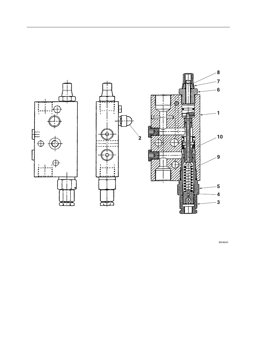
SHUT-OFF VALVE

TB125, 135, 145

Pilot Operated Hydraulic System (Boom and Arm Cylinder)

  1. Body
  2. Relief Valve
  3. Plug
  4. Screw
  5. Plug

  6. Plug
  7. Lock Nut
  8. Adjusting Screw
  9. Spring
10. Spool

IV-92-17

HYDRAULIC UNITS

SHUT-OFF VALVE

TB125, 135, 145

OPERATION

The isolation valve prevents the boom or arm being
raised from falling. If the hydraulic hose breaks, the
valve blocks and isolates the hydraulic oil flowing to
the cylinder head.

Differential Pressure Detection (TB145: For
Boom Cylinder Only)

When the boom is raised, the oil from the hydraulic
pump flows through the port H, the hole on the spool
(1), the passage (2) and the port C into the boom
cylinder. Meanwhile, the pressure from the ports C
and H is led to the chambers A and B located on each
side of the spool (1).

If the hydraulic hose breaks, the pressures between
the chambers A and B on the sides of the spool (1)
become different. The force caused by this differen-
tial pressure moves the spool (1) to the left when the
force becomes larger than the force of the spring (3).
Then the flow cross-section area of the passage (2)
decreases and the pressure in the chamber (A) moves
the spool (1) to be seated on the body, blocking the
ports C and H. As a result, the oil flowing to the
cylinder head is blocked, which prevents the boom
from falling.

Pilot Operated Hydraulic System (Boom and
Arm Cylinder)

When the boom or arm is raised, the pressure oil from
the hydraulic pump flows through the port V2 to push
up the check valve (1) and then through the port C2
into the boom or arm cylinder.

When the boom or arm is lowered, the pilot pressure
from the pilot valve (2) is led to the port PDB. The
pilot pressure in the port PDB moves the spool (3) to
the left. The return oil from the cylinder flows from
the port C2 to the passage through the spool (3) and
the check valve (1), the port V2 and into the tank
passage.

IV-92-18

HYDRAULIC UNITS

SHUT-OFF VALVE

TB125, 135, 145

The boom or arm does not fall in case of hydraulic
hose breakage, because the oil flow leading to the
boom or arm is blocked and isolated in the passage
through the check valve (1) and the spool (3) if a hose
breaks.

INSPECTION AND ADJUSTMENT

Never adjust the adjuster screws on the isolation
valve. Otherwise, the valve may not work properly, or
the boom or arm may fall.

IV-92-19

HYDRAULIC UNITS

SHUT-OFF VALVE

TB125, 135, 145

TROUBLESHOOTING

When the hose of the boom or arm cylinders are
ruptured and the boom or arm falls, the emergency
shut-off valve is activated and stops the boom or arm
part way through the fall.

If the boom or arm drops and the emergency
shut-off valves are activated, immediately move
away from the suspended object.

Differential Pressure Detection (TB145: For Boom
Cylinder Only)

1. Check for safety in the working area and for

stability of the machine and lifted load.

2. Loosen the emergency shut-off valve’s lock nut

(3) and stem (4) to lower the boom.

3. Check for stability of the hoe attachment and

load.

4. Tighten the stem (4) secure it with the lock nut (3).

Tightening torque:

Stem (4): 1.0 ~ 1.5 N·m
Lock nut (3): 3.2 N·m

Pilot Operated Hydraulic System (Boom and
Arm Cylinder)

If the engine can be started, the boom or arm can be
lowered with the operating lever. Check for safety,
then slowly lower the boom or arm.
If the engine cannot be started, the boom or arm can
be lowered using the procedure described below.

WARNING

IV-92-20

HYDRAULIC UNITS

SHUT-OFF VALVE

TB125, 135, 145

1. Check for safety in the working area and for

stability of the machine and lifted load.

2. Remove the cap (2).

3. Loosen the lock nut (3).

4. Tighten the stem (4) to lower the boom or arm.

5. Check for stability of the hoe attachment and

load.

6. Loosen the stem (4) secure it with the lock nut (3).

IV-92-21

HYDRAULIC UNITS

PROPORTIONAL CONTROL SOLENOID VALVE

TB125, 135, 145

PROPORTIONAL CONTROL SOLENOID VALVE (TB145)

CONSTRUCTION

A:

 7 

±

0.5 N·m

  1. Proportional Control Solenoid
  2. Bolt
  3. Spool

IV-92-22

HYDRAULIC UNITS

PROPORTIONAL CONTROL SOLENOID VALVE

TB125, 135, 145

T9H201

S

1

2

4

A1

A

P

T

B1

S=A1-B1

Fk

Paxs

Paxs

Fk

Fs

Fks

Fs

Fks

T9H202

1

5

P

A

T

T9H203

1

6

P

A

T

OPERATION PRINCIPLE

This valve controls the secondary pressure by using
the built-in proportional pressure reducing valve. The
secondary pressure of this valve is proportional to the
magnitude of electric current flowing in the valve,
because the force to generate the secondary pressure
is applied by the solenoid based on the current passing
through the coil.
When a current flows in the solenoid, a thrust force
proportional to the current is generated and moves the
spool (1) so that the oil supplied from Port P is led to
the secondary pressure side Port A, thus increasing
pressure Pa of Port A.
Pressure Pa is a function of the differential area S
between the cross sections A1 and B1 of the spool (1),
and the spool (1) is pushed to the solenoid side by the
oil pressure Pa 

×

 S. The spool (1) stops at a position

where the sum of the oil pressure Pa 

×

 S and the force

Fk exerted by the springs (2) is balanced with the
thrust force Fs generated by the solenoid. The weight
Fks of the spring (4) for fine adjustment of the
secondary pressure acts in the direction (left) to help
the thrust force from the solenoid.

When the thrust force is larger than the set value, the
spool (1) is moved to the left, connecting Port P
(primary, supply side) and Port A (secondary, dis-
charge side) through the notch (5).

When the thrust force is smaller than the set value, the
spool (1) is moved to the right, connecting Port A
(secondary, discharge side) and Port T (outlet to tank)
through the notch (6).
Therefore, the opening areas of the supply side notch
(5) and discharge side notch (6) are controlled by the
movement of the spool (1), and secondary (pilot)
pressure created by the thrust force generated by the
solenoid can be provided.

IV-92-23

HYDRAULIC UNITS

PROPORTIONAL CONTROL SOLENOID VALVE

TB125, 135, 145

DISASSEMBLY AND ASSEMBLY

General Cautions

• Carry out disassembly and assembly operations in

a clean place and place disassembled parts in clean
containers.

• Before disassembly, clean thoroughly around the

ports and remove paint or thread lock, etc. from all
joints with a wire brush.

• Clean disassembled parts with light oil or other

cleaning oil.

• The spool and body are selectively fitted, so if one

is found to be damaged, replace the valve assem-
bly.

• Apply a thin coating of hydraulic oil to sliding

surfaces and a thin coating of grease to seals when
assembling them.

• Replace seals with new parts each time disassem-

bly is done.

The following describes the disassembly procedure.
For assembly, follow the disassembly procedure in
the reverse order.

Disassembly

1. Remove the bolts, and then remove the propor-

tional control solenoid (1).

Bolt: 6.9 

±

1 N·m

2. Remove the O-rings from the proportional con-

trol solenoid (1).
• Do not disassemble the sleeve (2) that is swaged

onto the solenoid (4) with the retaining ring
(3).

• Make sure that the spool (5) moves a little if

pushed from the sleeve (2) end.

T9H204

1

T9H205

4

3

2

5

IV-92-24

HYDRAULIC UNITS

PROPORTIONAL CONTROL SOLENOID VALVE

TB125, 135, 145

INSPECTION AND ADJUSTMENT

Checking the Parts

Part

Judgment Criteria

Treatment

• When the solenoid is burned, short-circuited, or has a wire

break

• Wiring short-circuit or wire break

• Scratches, rust, or corrosion at the sliding parts with the

spool

• Scratches, rust, or corrosion of the seal part in contact with

the O-ring

• Other damage considered to impair the normal functions

• Damage on the outer circumference which catches a finger-

nail

• No smooth movement

• Rust, corrosion, deformation, breakage, or other notable

damage

Coil assembly

Housing

Spool

Spring

O-ring

• Replace

• Replace

• Replace

• Replace

• Replace

• Replace

• Adjust or replace

• Replace

• Replace

Symptom

Main Causes

Remedy

• Wiring short-circuit or wire break
• Coil assembly short-circuit or wire break
• Catching of foreign matter by the spool

• Damage on the outer circumference of the spool

• Defective the proportional controller
• Primary pressure is insufficient

Oil leakage from sole-
noid valve

• Replace
• Replace
• Overhaul and repair or re-

place

• Overhaul and repair or re-

place

• Repair or replace
• Keep the primary pressure

Solenoid valve does
not operate

TROUBLESHOOTING



• Replace
• Replace

• Damaged O-ring
• Damaged seal nut

IV-93

HYDRAULIC UNITS

CYLINDERS

TB125, 135, 145

CYLINDERS

CONSTRUCTION

Boom Cylinder

TB125, TB135

  1. Stopper
  2. Connector
  3. Piston Packing
  4. Rod Packing
  5. Dust Seal
  6. Backup Ring
  7. Bushing

  8. O-ring
  9. O-ring
10. O-ring
11. Piston Rod
12. Bushing
13. Rod Cover
14. Cushion Bearing

15. Piston
16. Tube
17. Cushion Seal
18. Spacer
19. Stopper
20. Wear Ring
21. Bushing

22. Ball
23. Set Screw
24. Dust Seal
25. Grease Nipple
26. Grease Nipple
27. Retainer

TB145: S/N 14510004~14510788

  1. Ring
  2. Backup Ring
  3. Piston Packing
  4. Rod Packing
  5. Dust Seal
  6. Backup Ring
  7. Backup Ring

  8. O-ring
  9. O-ring
10. O-ring
11. Piston Rod
12. Bushing
13. Rod Cover
14. Cushion Bearing

15. Piston
16. Tube
17. Cushion Seal
18. Spacer
19. Stopper
20. Wear Ring
21. Bushing

22. Packing Holder
23. Set Screw
24. Dust Seal
25. Grease Nipple
26. Grease Nipple
27. Retainer
28. O-ring

E5D400

26

24

7

11

21

4

27

17

18

5

13 

9

6

8

2

1

6

10

19

12

16

14

24 25

15

20

3

20

23

22

K3D400

12

21

6

4

17

18

12

24 25

23 15 20

3

22 28

14

11

16

19 10

7

27 1

9

2

8 13 5

24

26

IV-94

HYDRAULIC UNITS

CYLINDERS

TB125, 135, 145

TB145: S/N 14510798~14511246

  1. Tube
  2. Piston Rod
  3. Rod Cover
  4. Bushing
  5. Rod Packing
  6. Dust Seal

  7. O-ring
  8. O-ring
  9. O-ring
10. Backup Ring
11. Cushion Bearing
12. Spacer

13. Piston
14. Piston Packing
15. Wear Ring
16. Set Screw
17. Ball
18. Bushing

19. Dust Seal
20. Grease Nipple
21. Grease Nipple

TB145: S/N 14511247~

  1. Tube
  2. Piston Rod
  3. Rod Cover
  4. Bushing
  5. Rod Packing
  6. Dust Seal
  7. O-ring

  8. Backup Ring
  9. O-ring
10. Holder
11. Cushion Ring
12. Collar
13. Spacer
14. Backup Ring

15. Cushion Bearing
16. Piston
17. Piston Packing
18. Wear Ring
19. Set Screw
20. Ball
21. Bushing

22. Dust Seal
23. Bushing
24. Grease Nipple
25. Grease Nipple

IV-93-1

IV-95

HYDRAULIC UNITS

CYLINDERS

TB125, 135, 145

  1. Tube
  2. Piston Rod
  3. Rod Cover
  4. Bushing
  5. Rod Packing
  6. Dust Seal

Arm Cylinder

TB125

  7. O-ring
  8. Backup Ring
  9. O-ring
10. Piston
11. Wear Ring
12. Piston Packing

13. Ball
14. Set Screw
15. Dust Seal
16. Grease Nipple
17. Grease Nipple
18. Bushing

19. Bushing
20. Packing Holder
21. Snap Ring

TB135

  1. Tube
  2. Piston Rod
  3. Rod Cover
  4. Bushing
  5. Rod Packing
  6. Dust Seal

  7. O-ring
  8. Backup Ring
  9. O-ring
10. Piston
11. Wear Ring
12. Piston Packing

13. Ball
14. Set Screw
15. Dust Seal
16. Grease Nipple
17. Grease Nipple
18. Bushing

19. Bushing
20. Packing Holder
21. Snap Ring
22. Cushion Bearing
23. Bolt
24. Washer

E5D401

2

18

15

20

21

7

8

5

4

9

3

6

17

15

16

1

19

10

11

12

11

14

13

G4D400

15

19

2

17

4

5

20

6

3

9

8

7

21

18

1

16 15 23 24 22 13 14 11 12 11 10

IV-94

IV-96

HYDRAULIC UNITS

CYLINDERS

TB125, 135, 145

TB145

  1. Tube
  2. Piston Rod
  3. Rod Cover
  4. Bushing
  5. Rod Packing
  6. Dust Seal
  7. O-ring

  8. Backup Ring
  9. O-ring
10. Piston
11. Wear Ring
12. Piston Packing
13. Backup Ring
14. Set Screw

15. Dust Seal
16. Grease Nipple
17. O-ring
18. Bushing
19. Backup Ring
20. O-ring
21. Packing Holder

22. Cushion Bearing
23. PG-ring
24. Cushion Seal
25. Spacer
26. Stopper
27. Bushing
28. Retainer

Bucket Cylinder

TB125

  1. Tube
  2. Piston Rod
  3. Rod Cover
  4. Bushing
  5. Rod Packing
  6. Backup Ring

  7. Dust Seal
  8. O-ring
  9. Backup Ring
10. O-ring
11. Piston
12. Wear Ring

13. Piston Packing
14. Packing Holder
15. O-ring
16. Bushing
17. Grease Nipple
18. Grease Nipple

19. Dust Seal
20. Nut
21. Split Pin
22. Packing Holder
23. Snap Ring
24. Bushing

K3D401

15

16

18

4

8

5

24

25

26

6

3

7

13

9

23

28

19

17

1

2

22

20

21

12

11

10

14

15

27

E5D402

19

16

4

6

5

17

7

3

10

9

8

22

23

1

2

14

12

15

13

12

11

20

21

19

18

24

IV-95

IV-97

HYDRAULIC UNITS

CYLINDERS

TB125, 135, 145

TB135

  1. Tube
  2. Piston Rod
  3. Rod Cover
  4. Bushing
  5. Rod Packing
  6. Backup Ring

  7. Dust Seal
  8. O-ring
  9. Packing Holder
10. O-ring
11. Piston
12. Wear Ring

13. Piston Packing
14. Ball
15. Set Screw
16. Dust Seal
17. Grease Nipple
18. Grease Nipple

19. Bushing
20. Bushing
21. Snap Ring

TB145

  1. Tube
  2. Piston Rod
  3. Rod Cover
  4. Bushing
  5. Rod Packing
  6. Backup Ring

  7. Dust Seal
  8. O-ring
  9. Packing Holder
10. O-ring
11. Piston
12. Wear Ring

13. Piston Packing
14. Backup Ring
15. Set Screw
16. Bushing
17. Grease Nipple
18. Grease Nipple

19. Dust Seal
20. O-ring
21. Snap Ring
22. Packing Holder

G4D401

2

20

16

18

9

7

3

10

4

5

6

8

21

11

12

13

12

15

14

1

19

16

17

K3D402

19

16

4

6

5

17

7

3

8

14

10

9

21

1

2

16

18

19

22

20

13

11

15

12

IV-96

IV-98

HYDRAULIC UNITS

CYLINDERS

TB125, 135, 145

  1. Tube
  2. Piston Rod
  3. Rod Cover
  4. Bushing
  5. Rod Packing
  6. Dust Seal

Dozer Blade Cylinder

TB125, TB135

  7. O-ring
  8. Backup Ring
  9. O-ring
10. Piston
11. Wear Ring
12. Piston Packing

13. Ball
14. Set Screw
15. Dust Seal
16. Grease Nipple
17. Grease Nipple
18. Bushing

19. Bushing
20. Packing Holder
21. Snap Ring

TB145

  1. Tube
  2. Piston Rod
  3. Rod Cover
  4. Bushing
  5. Rod Packing
  6. Backup Ring

  7. Dust Seal
  8. O-ring
  9. Packing Holder
10. O-ring
11. Piston
12. Wear Ring

13. Piston Packing
14. Backup Ring
15. Set Screw
16. Dust Seal
17. Grease Nipple
18. Grease Nipple

19. Bushing
20. O-ring
21. Snap Ring
22. Packing Holder

E5D403

2

18

15

20

17

6

3

9

4

5

8

7

21

10

11

12

11

14

13

16

15

19

1

K3D403

16

18

19

4

6

5

7

3

8

14

10

9

21

1

2

17

19

16

15

11

12

13

20

22

IV-97

IV-99

HYDRAULIC UNITS

CYLINDERS

TB125, 135, 145

  1. Tube
  2. Rod Cover
  3. Piston Rod
  4. Piston
  5. Packing Holder
  6. Cushion Bearing
  7. Retainer
  8. Ring

Swing Cylinder

TB125

  9. Cushion Seal
10. Bushing
11. Bushing
12. Grease Nipple
13. Bushing
14. Set Screw
15. Set Screw
16. Wear Ring

17. Piston Packing
18. Rod Packing
19. Backup Ring
20. Dust Seal
21. O-ring
22. O-ring
23. Backup Ring
24. O-ring

25. Backup Ring
26. O-ring
27. Dust Seal
28. Cushion Bearing
29. Cushion Seal
30. Stopper

TB135

  1. Tube
  2. Piston Rod
  3. Rod Cover
  4. Bushing
  5. Rod Packing
  6. Dust Seal
  7. O-ring
  8. Backup Ring

  9. O-ring
10. Retainer
11. Cushion Seal
12. Spacer
13. Stopper
14. O-ring
15. Connector
16. Stopper

17. Piston
18. Piston Packing
19. Wear Ring
20. Cushion Bearing
21. Ball
22. Set Screw
23. Cushion Bearing
24. Washer

25. Bolt
26. Bushing
27. Dust Seal
28. Grease Nipple
29. Bushing

G4D402

27

28

29

2

4

5

10

11

12

6

3

9

8

7

15

16

8

14

13

20

17

19

18

19 

22

21

23

24

25

27

26

1

IV-98


Content      ..     22      23      24      25     ..