Takeuchi compact excavator TB125, TB135, TB145 / diesel TNE / diesel Yanmar. Service Manual - page 22
 

  Index      Manuals     Takeuchi compact excavator TB125 (12510003~), TB135 (13510004~), TB145 (14510004~) / diesel TNE / diesel Yanmar. Service Manual


Search            copyright infringement  


Content      ..     20      21      22      23     ..


Takeuchi compact excavator TB125, TB135, TB145 / diesel TNE / diesel Yanmar. Service Manual - page 22


IV-76

HYDRAULIC UNITS

CONTROL VALVE

TB125, 135, 145

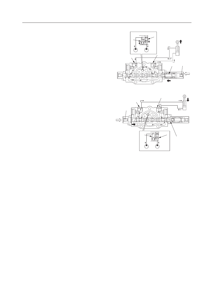
Arm Conflux Circuit

When Moving the Arm In

When the pilot port (1) is pressurized and the spool (2)
is switched, the hydraulic oil from the pump P2
pushes up the load check valve (3) and flows into the
cylinder port (4). The hydraulic oil from the pump P3
joins the oil from the pump P2 through the poppet (5),
pushing up the load check valve (3) to let the oil flow
into the cylinder port (4). The resulting oil flow equals
the total oil flow from the pump P2 and pump P3.
The returning oil from the cylinder port (6) flows into
the tank passage and returns to the tank.

When Moving the Arm Out

When the pilot port (7) is pressurized and the spool (2)
is switched, the hydraulic oil from the pump P2
pushes up the load check valve (3) and flows into the
cylinder port (6). The hydraulic oil from the pump P3
joins the oil from the pump P2 through the poppet (5),
pushing up the load check valve (3) to let the oil flow
into the cylinder port (6). The resulting oil flow equals
the total oil flow from the pump P2 and pump P3.
The returning oil from the cylinder port (4) flows into
the tank passage and returns to the tank.

K3D215

4

6

2

1

5

3

P3

P2

K3D216

5

4

6

2

7

3

P3

P2

IV-77

HYDRAULIC UNITS

CONTROL VALVE

TB125, 135, 145

DISASSEMBLY AND ASSEMBLY

General Cautions

• Since all parts in control valves are precision

machined, carry out disassembly and assembly
operations in a clean place.

• Before disassembly, clean the outside surfaces

around the valves.

• Clean each of the disassembled parts and apply

clean hydraulic oil to them.

• Apply hydraulic oil to sliding surfaces and apply a

thin coating of grease to seals when assembling
them.

• Replace all seals with new ones each time the

valves are disassembled.

• Spools and section bodies are specially selected for

a precise fit. Therefore, if any damage is found in
either of these parts, replace the section assembly
as a unit.

• Be sure to number each section and spool to avoid

mistakes during assembly.

Following is an explanation of the control valve
disassembly procedure.
Follow the procedure used to disassemble the control
valve in reverse order when reassembling it.
• Before disassembly, number each section and spool.

Disassembly

Valve Assembly

1. Loosen the nuts and remove the tie rods, then

remove the sections.
• Nut tightening torque:

46.2 

±

2 N·m (4.7 

±

0.2 kgf·m)

2. Remove the O-ring.

• The mating surfaces are metal seals, so be

careful not to scratch, bruise or otherwise dam-
age them.

3. Remove the main relief valves and the port relief

valves, then remove the O-rings from the relief
valves.
• Do not disassemble the relief valves unless it is

necessary.

• When using a spanner or adjustable wrench, be

sure to attach it in the place shown in the figure
at right.

• Relief valve tightening torque:

68.6~78.5 N·m (7~8 kgf·m)

G4D223

IV-78

HYDRAULIC UNITS

CONTROL VALVE

TB125, 135, 145

4. Remove the anti-cavitation valve (1) and remove

the O-ring (2) from the valve.
• Plug tightening torque:

69~78 N·m (7~8 kgf·m)

5. Remove the load check valve.

• Remove the spring (3), then remove the poppet

(4).

Manually Operated Section

1. Remove the cap screws (5), the cover (6) and the

spool assembly (7).
• Cap screw tightening torque:

8.8~10.8 N·m (0.9~1.1 kgf·m)

2. Loosen the screw (8) from the spool assembly (7).

• Screw tightening torque:

19~22 N·m (1.9~2.2 kgf·m)

IV-79

HYDRAULIC UNITS

CONTROL VALVE

TB125, 135, 145

3. Remove the spring holder (9), spring (10), and

spring holder (9).

4. Remove the seal holder (12), then remove the

backup ring (13) and O-ring (14).

5. Remove the screws on the spool yoke end side of

the section, then remove the seal holder, backup
ring and O-ring.
• Screw tightening torque:

2.5~2.9 N·m (0.25~0.3 kgf·m)

Pilot Operated Section

1. Take out the cap screw (5) and remove the cover

(15), then remove the O-ring (16) from the cover
(15).
• Cap screw tightening torque:

8.8~10.8 N·m (0.9~1.1 kgf·m)

IV-80

HYDRAULIC UNITS

CONTROL VALVE

TB125, 135, 145

2. Remove the spool from the section.

3. Take out the screw (17) and remove the spring

holder (18), spring (19) and spring holder (20).
• Screw tightening torque:

19~22 N·m (1.9~2.2 kgf·m)

4. a. Take out the cap screws (5) and remove the

cover (21).

b. Remove the O-ring (16) from the cover (21).

• Cap screw tightening torque:

8.8~10.8 N·m (0.9~1.1 kgf·m)

K3D217

K3D218

17

18

19

20

K3D219

5

21

16

IV-81

HYDRAULIC UNITS

CONTROL VALVE

TB125, 135, 145

Main Relief Valve

1. Separate the plug assembly (1) from the housing

assembly (2).
• Tightening torque:

68.6~78.5 N·m (7~8 kgf·m)

2. Disassemble the plug assembly (1).

a. Remove the lock nut (3), washer (4) and set

screw (5) from the plug (6), then remove the O-
ring (7) from the set screw (5).
• During assembly, after installing the set

screw (5), lock the lock nut (3) temporarily,
then tighten it after adjusting the pressure.

• Lock nut tightening torque:

27.5~31.4 N·m (2.8~3.2 kgf·m)

b. Remove the needle valve (8) and spring (9),

then remove the O-ring (11) from the plug (6).

3. Disassemble the housing assembly (2).

a. Remove the sleeve (12) and O-ring (13) from

the housing (14).

b. Remove the piston (15), spring (16) and main

poppet (17) from the sleeve (12), then remove
the O-ring (18) and backup ring (19) from the
piston (15).

K3D220

7

5

4

3

6

11

9

8

IV-82

HYDRAULIC UNITS

CONTROL VALVE

TB125, 135, 145

INSPECTION AND ADJUSTMENT

Checking the Parts

Adjusting the Main Relief Valve Pressure

1. Install a pressure gauge in the following pressure

sensor port.
• Control valve pressure sensor port.

 “II. Specifications, Standards for Judg-
ing Performance”

2. Run the pump at the rated speed.
3. Operate the control valve’s cylinder spool over its

full stroke and read the value indicated by the
pressure gauge.

4. Turn the set screw (1) while watching the pres-

sure gauge to adjust.
Turning it to the right increases the set pressure.
Turning it to the left decreases the set pressure.

5. After completing the pressure adjustment, tighten

the lock nut (2) while holding the set screw (1) so
it won’t turn.
Operate the relief valve again and check if the
pressure is stabilized.

Parts

Judgment Criteria

Treatment

• Replace

• Replace

• Replace

• Replace

• Replace

Housing,
Section Body

• Scratches, rust, corrosion of the portion which slides

against the spool.

• Scratches, rust, corrosion of the seal pocket portion of

the part that enters the spool.

• Scratches, rust, corrosion of the port seal portion which

is in contact with the O-ring.

• Scratches, rust, corrosion of the seal portion of the relief

valve, etc.

• Other damage which could be a hindrance to correct

function.

• Scratch marks like being clawed around the outer cir-

cumference sliding portion.

• Scratches on the portion that slides against the seals on

both ends.

• Spool not operating smoothly.
• Imperfect sealing due to damage to the valve or spring.
• Does not catch, but operates lightly when inserted in the

section body and operated.

• Rust, corrosion, deformation, breakage or other marked

damage to the spring, holder or cover.

• Oil leaking to the outside.
• Rust, corrosion or deformation of the seal holder.
• External rust, damage.
• Damage to valve seat contact surface.
• Damage to poppet contact surface.
• Abnormality in the spring.
• O-rings, backup rings, seals

• Replace

• Replace

• Repair or replace.
• Normal

• Replace

• Repair or replace.
• Replace
• Replace
• Replace
• Replace
• As a rule, all these

should be replaced.

Spool

Load Check Valve

Around Springs

Around Spool Seal

Main Relief Valve,
Port Relief Valve,
Anti-Cavitation Valve

2

G4B0241

1

< TB145 >

IV-83

HYDRAULIC UNITS

CONTROL VALVE

TB125, 135, 145

TROUBLESHOOTING

“IV-62~64”

IV-84

HYDRAULIC UNITS

CONTROL VALVE

TB125, 135, 145

IV-85

HYDRAULIC UNITS

PILOT VALVE

TB125, 135, 145

  1. Retainer
  2. Spring Holder
  3. Push Rod
  4. Joint
  5. Cam
  6. Plate
  7. Shim
  8. Shim
  9. Casing

PILOT VALVE

(TB125: S/N 12510003~12514525, TB135: S/N 13510004~13514050, TB145: S/N 14510004~14513260)

CONSTRUCTION

10. Port Plate
11. Push Rod
12. Spring Holder
13. Piston
14. Spool
15. Wire Ring
16. Spring
17. Spring
18. Spring

19. Spring
20. Nut
21. Sleeve
22. Cap Screw
23. Cap Screw
24. U-Packing
25. O-ring
26. O-ring
27. O-ring

C4D300

22

11

12

17

7.8

18

20

4

5

3

24

21

6

25

1

2

16

19

14

9

10

15

7.8

13

26

27

23

IV-86

HYDRAULIC UNITS

PILOT VALVE

TB125, 135, 145

OPERATION

The pilot valve casing contains a vertical shaft hole
with a reducing valve incorporated into it. When the
handle is tilted, the push rod and spring seat are
pushed down changing the secondary pressure spring’s
pressure.

The casing also contains an inlet port for hydraulic oil,
port P (primary pressure), and an outlet port, port T
(tank), and secondary pressure is taken from 4 ports,
port 1, port 2, port 3 and port 4, on the bottom of the
vertical shaft hole.

1. When the Handle is in Neutral

In this case, the force of the secondary pressure
setting spring, which determines the pilot valve’s
output pressure (secondary pressure), is not trans-
mitted to the spool. Therefore, the spool is pushed
up by the return spring and is in the output port C
position shown above, with oil not flowing be-
tween port P and the output port C but flowing
between the T port and output port C.

2. When the Handle is Tilted

When the handle (1) is tilted and the push rod is
pushed, the spool moves downward and port P
and port A are joined. The oil in the pilot valve
pump flows out to port A, generating pressure.
When the pressure in port A is the same as the set
force of the spring (set pressure), there is a bal-
ance between the hydraulic pressure and the spring
force.
When the pressure in port A is greater than the set
pressure, port A and port P close and port A and
port T open.
When the pressure at port A is lower than the set
pressure, port A and port P open and port A and
port T close.
In this way, the secondary pressure is kept con-
stant.

WHEN TILTED

WHEN IN NEUTRAL

IV-87

HYDRAULIC UNITS

PILOT VALVE

TB125, 135, 145

DISASSEMBLY AND ASSEMBLY

General Cautions

• Since all parts in the pilot valve are precision

machined, carry out disassembly and reassembly
operations in a clean place and take special care not
to scratch the parts.

• Before disassembly, clean the outside surfaces of

the pilot valve.

• Clean each of the disassembled parts and apply

clean hydraulic oil to them.

• Replace all seals with new ones each time the pilot

valve is disassembled.

• During assembly, remove all the foreign matter

from each part and check them to make sure there
are no burrs, bruises using or other marks on them.
Remove all burrs and bruises using an oil stone.

• Apply thin coating of grease to seals when assem-

bling them.

Disassembly

1. Remove the nut (1) and separate the joint from the

cam (2).
• Fix the valve to the vise using a copper plate or

lead plate.

2. Remove the joint (3).

3. Loosen the cap screws at the bottom and remove

the port plate (4).

4. Remove the four pistons (5), one O-ring (6), and

six O-rings (7).

5. Loosen the cap screws and remove the plate (8).

6. Remove the push rods (9) together with the sleeves

(10).
• The push rods for port 1 and port 3 are different

from those for port 2 and port 4. Store them
carefully so that they can be restored at the
same positions when assembling.

C4D301

1

2

3

C4D302

4

5

6

7

C4D303

8

9

10

IV-88

HYDRAULIC UNITS

PILOT VALVE

TB125, 135, 145

C4D304

12

10

11

C4D305

13

14

C4D306

C
D

17

15
19
18

20

7. Remove the O-ring (11) and U-packing (12) from

the sleeve (10).

8. Remove the spool assembly (13) and spring (14)

from the casing.
• The spool assemblies and springs for port 1

and port 3 are different from those for port 2
and port 4. Store them carefully so that they can
be restored at the same positions when assem-
bling.

9. Disassemble the spool assembly.

a. Push down the spring holder (15) and remove

the retainer (17) from the spool (18).

b. Remove the spring holder (15) and spring (19)

from the spool (18).
• Be careful not to lose the pressure adjusting

shim (20) if assembled.

IV-89

HYDRAULIC UNITS

PILOT VALVE

TB125, 135, 145

C4D307

15

19

18

A

B

C4D306

C
D

17

15
19
18

20

C4D305

13

14

C4D304

12

10

11

Assembly

1. Assemble the spring assembly.

a. Fit the spring (19) to the spool (18) and install

the spring holder (15).
• Be careful of the direction of the spring

holder.
A: Make the side with the deeper hole up.
B: Make the side with the shallow hole down.

b. Push down the spring holder (15) and fit the

retainer (17) to the spool (18).
• Be careful of the direction of the retainer.

C: Make the side with the sharp corner up.
D: Make the side with the round corner down.

2. Install the spring (14) and spool assembly (13) in

the casing.
• Install them at the same positions as previously

assembled.

• Be careful not to damage the spool hole.

3. Install the O-ring (11) and U-packing (12) in the

sleeve (10).
• Be careful of the direction of the U-packing.

IV-90

HYDRAULIC UNITS

PILOT VALVE

TB125, 135, 145

C4D303

8

9

10

C4D308

5

A

6

7

4

C4D301

1

2

3

4. Assemble the push rods (9) and sleeves (10), and

mount them on the spool assemblies in the casing.
• Install them at the same positions as previously

assembled.

• Be careful not to damage the parts by pushing

them too strongly.

5. Mount the plate (8) and tighten the cap screws.

• Cap screw tightening torque:

23.5 

±

2 N·m (2.4 

±

0.2 kgf·m)

6. Turn the casing upside down to make the push

rods the lower side and insert the four pistons (5)
into the spool holes.
• Let the side A with the smaller diameter (un-

polished side) of the piston be positioned in the
back of the holes.

7. Install one O-ring (6), six O-rings (7) and the port

plate (4) in the casing and tighten them with the
cap screws.
• Cap screw tightening torque:

23.5 

±

2 N·m (2.4 

±

0.2 kgf·m)

8. Reverse the casing again to the original position

and install the joint (3).
• Joint tightening torque:

49 

±

4.9 N·m (5 

±

0.5 kgf·m)

• Apply Loctite #242 to the joint screws.

9. Tighten the cam (2) with your fingers until it

touches the push rod. Loosen the cam at an angle
of around 45

°

 before tightening the nut (1).

• Nut tightening torque:

49 

±

4.9 N·m (5 

±

0.5 kgf·m)

IMPORTANT: Never tighten the nut without
loosening the cam, otherwise the cam will rotate
with the nut, keeping the push rods pressed. This
will generate secondary pressure in the neutral
position that might cause erroneous operation.

10. Apply grease to the cam, push rods and joint

rotating section.

IV-91

HYDRAULIC UNITS

PILOT VALVE

TB125, 135, 145

• Replace

INSPECTION AND ADJUSTMENT

Checking the Parts

Parts

Judgment Criteria

Treatment

O-ring



Seal
Seal Washer




• Wear on sliding portions is 10 

µ

m or greater compared to non-

sliding portions

• Scratches on sliding portions
• Spool doesn’t move smoothly
• Front end is worn 1 mm or more

• Scratches in the sliding portion
• Seal is imperfect due to damage
• Tightening is loose at the pin, shaft or joint of the operating

portion, with looseness of 2 mm or greater

• Due to wear, etc. tightening is loose at the pin, shaft or joint of

the operating portion, with looseness of 2 mm or greater

• Scratches, rust or corrosion on the spool and sliding portion
• Scratches, rust or corrosion on seal portions which come in

contact with the O-ring

Spool

Push Rod

Plug
Operating Portion

Casing,
Port Plate

• Replace
• Replace
• Replace

• Replace
• Repair or replace
• Replace

• Replace
• Repair or replace
• Tighten to the speci-

fied torque

• Replace

• Replace
• Repair or replace


Content      ..     20      21      22      23     ..