Takeuchi compact excavator TB125, TB135, TB145 / diesel TNE / diesel Yanmar. Service Manual - page 25
 

  Index      Manuals     Takeuchi compact excavator TB125 (12510003~), TB135 (13510004~), TB145 (14510004~) / diesel TNE / diesel Yanmar. Service Manual


Search            copyright infringement  


Content      ..     23      24      25      26     ..


Takeuchi compact excavator TB125, TB135, TB145 / diesel TNE / diesel Yanmar. Service Manual - page 25


IV-100

HYDRAULIC UNITS

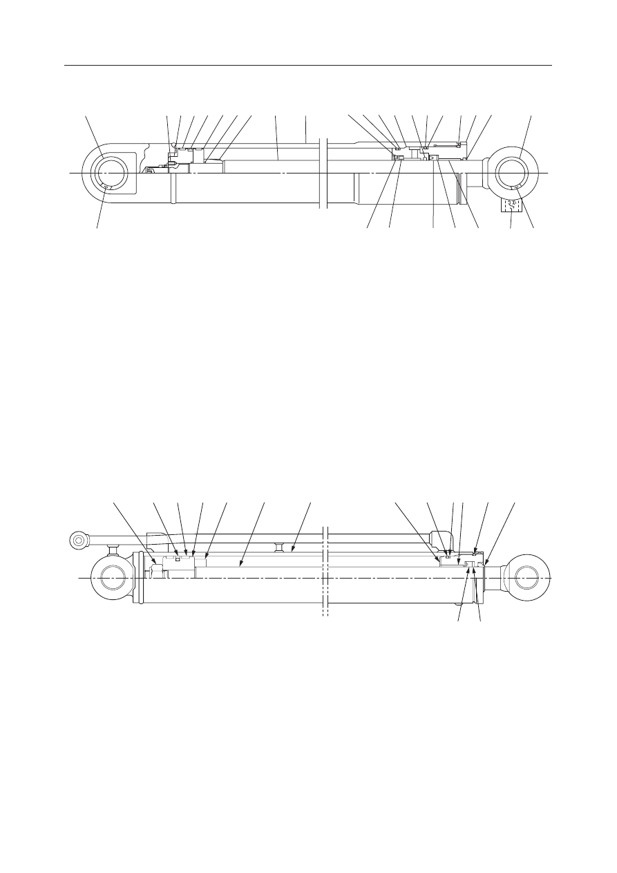
CYLINDERS

TB125, 135, 145

TB145

  1. Tube
  2. Piston Rod
  3. Rod Cover
  4. Bushing
  5. Rod Packing
  6. Dust Seal
  7. O-ring

  8. Backup Ring
  9. O-ring
10. Piston
11. Wear Ring
12. Piston Packing
13. Backup Ring
14. Set Screw

15. Dust Seal
16. Grease Nipple
17. O-ring
18. Bushing
19. Backup Ring
20. O-ring
21. Packing Holder

22. Cushion Bearing
23. PG-ring
24. Cushion Seal
25. Spacer
26. Stopper
27. Bushing
28. Retainer

  1. Tube
  2. Piston Rod
  3. Rod Cover
  4. Bushing

Telescopic Arm Cylinder

TB135

  5. Rod Packing
  6. Dust Seal
  7. O-ring
  8. Backup Ring

  9. O-ring
10. Piston
11. Wear Ring
12. Piston Packing

13. Backup Ring
14. Spacer
15. Nut

K3D404

15

18

16

4

8

5

24

25

1

2

26 17 19 28 23

9 13

7

3

6

27

15

22

20

21

12

11

10

14

G4D403

8

5

6

7

4

13

9

3

1

2

14

10

11

12

15

IV-99

IV-101

HYDRAULIC UNITS

CYLINDERS

TB125, 135, 145

  1. Tube
  2. Piston Rod
  3. Rod Cover
  4. Bushing

TB145

  5. Rod Packing
  6. Dust Seal
  7. O-ring
  8. Backup Ring

  9. O-ring
10. Piston
11. Wear Ring
12. Piston Packing

13. Ball
14. Set Screw
15. Spacer
16. Backup Ring

K3D405

8

5

2

7 16

3 4 9

6

1

15

10

11

12

14

13

IV-100

IV-102

HYDRAULIC UNITS

CYLINDERS

TB125, 135, 145

IV-100-1

IV-103

HYDRAULIC UNITS

CYLINDERS

TB125, 135, 145

OPERATION

Hydraulic oil flowing alternately in and out of the oil
outlet and inlet on both sides (head and rod sides) of
the piston acts on the piston and its force causes the
piston to move back and forth.
In cylinders equipped with a cushion mechanism, the
shock resulting from the piston colliding with the
cover at the stroke end acts on that mechanism and is
dampened by it.

Cushion Mechanism

Before the piston (1) nears the stroke end and collides
with the cover (2), the cushion bearing (3) which
precedes it enters the cushion seal (4), shutting off the
return passage for the hydraulic oil on the rear end of
the piston and making it possible for oil to be expelled
only along the groove provided in the cushion bearing
(3). This causes the piston (1) back pressure to be-
come high, slowing the speed of the piston.

E5D405

2

4

3

1

E5D406

2

4

3

1

IV-101

IV-104

HYDRAULIC UNITS

CYLINDERS

TB125, 135, 145

DISASSEMBLY AND ASSEMBLY

Special Tools

See the table of special tools at the back of this section
for the jigs and tools used for disassembly and assem-
bly.

General Cautions

• Carry out disassembly and assembly in a clean

place and place the disassembled parts in a place
where they will be kept clean at all times.

• Before disassembly, clean the outside surface of

the cylinder thoroughly.

• In the disassembly and assembly operations, be

careful not to scratch any part. Take particular
caution with the sliding surfaces of parts.

• Clean all disassembled parts thoroughly with clean-

ing oil.

• Replace all seals with new parts.
• Apply a thin coating of hydraulic oil to seals before

fitting them in place.

• After fitting, make sure the O-rings are not twisted.
• Apply clean hydraulic oil to each sliding portion

before assembling them.

In this manual, the procedure for the boom cylinder is
described. When necessary, the points which are
different in other cylinders are mentioned.

Disassembly

Cylinder Assembly

1. Fasten the clevis of the tube in a vice and place the

other end on a support black made of wood to
fasten the cylinder in a horizontal condition.

2. Drain out hydraulic oil remaining in the cylinder.

• Move the piston rod gently to prevent the

hydraulic oil from spraying out and scattering
all over.

3. Free the locked portion of the rod cover.

• Since the lock is integrated with the cylinder

tube, be careful not to bend it or to scratch it
when the lock is being freed.

IV-102

IV-105

HYDRAULIC UNITS

CYLINDERS

TB125, 135, 145

4. Loosen the rod cover.

• The piston rod should be pulled out approxi-

mately 200 mm beforehand.

• Measures should be taken to prevent the piston

rod from being hit.

5. Take the piston rod assembly out of the tube.

• Pull it out straight to prevent the sliding surface

from being scratched.

Piston Rod Assembly

1. Fasten the piston rod assembly securely in a level

position.

2. Remove the piston.

a. Take out the set screw (1) and remove the ball.

• The set screw is staked at 2 place with a

punch, so grind off the staked portions using
a hand drill.

b. Remove the piston assembly (2).
c. Remove the cushion bearing (3) and spacer.

E5D408

1

3

2

IV-103

IV-106

HYDRAULIC UNITS

CYLINDERS

TB125, 135, 145

a. Take out the split pin and remove the nut (4).
b. Remove the piston assembly (2) and the pack-

ing holder (5), then remove the O-ring from the
inner diameter of the piston assembly.

a. Remove the set screw (1).
b. Remove the piston assembly (2) and the pack-

ing holder (5), then remove the O-ring from the
inner diameter of the piston assembly.

c. Remove the cushion bearing (3). Furthermore,

the head side cushion bearing should not be
removed.

3. Remove the rod cover assembly.

E5D409

2

4

5

E5D410

5

2

1

3

E5D411

5

2

1

3

IV-104

IV-107

HYDRAULIC UNITS

CYLINDERS

TB125, 135, 145

4. Separate the rod cover assembly (6) and retainer

assembly (7).
a. Remove the stopper (8) and separate the con-

nector (9) into two to separate it from the rod
cover assembly.

a. Turn the retainer (7) until the bent part at the tip

of the ring (10) can be seen in the notched part
of the rod cover (6).

b. Pull the tip of the ring (10) with pliers while

turning the retainer (7) to pull the ring (10).

Piston

1. Remove the wear ring (11), then remove the

piston packing (12).
• Spread the wear ring at the cut portion the

minimum amount necessary for it to be re-
moved. Remove it in the direction of the shaft.

• Either cut the piston packing off or use a flat

bladed screwdriver, etc. to take it off.

1. Remove the wear ring (11) from the piston (13)

and the packing holder (5).
• Spread the wear ring at the cut portion the

minimum amount necessary for it to be re-
moved, Remove it in the direction of the shaft.

2. Remove the piston packing (12).

E5D412

6

9

7

8

9

E5D413

7

10

6

E5D414

12

11

E5D415

12

11

13

  5

IV-105

IV-108

HYDRAULIC UNITS

CYLINDERS

TB125, 135, 145

Retainer Assembly

1. Remove the O-ring (14) and backup ring (15).

2. Remove the stopper (16), spacer (17) and cushion

seal (18).

Remove the stopper (16), spacer (17), cushion
seal (18) and ring (19).

Rod Cover

1. Remove the O-ring (20) from the outer diameter

of the rod cover, then remove the backup ring
(21).

E5D416

14

15

E5D417

18

17

16

E5D418

18

17

16

19

E5D419

20

21

IV-106

IV-109

HYDRAULIC UNITS

CYLINDERS

TB125, 135, 145

2. Remove the rod packing.

a. Remove the rod packing (22).
b. Remove the backup ring (23).

a. Remove the snap ring (24).
b. Remove the packing holder (25).
c. Remove the rod packing (22).

a. Remove the snap ring (24).
b. Remove the packing holder (25).
c. Remove the rod packing (22).
d. Remove the backup ring (23).

3. Remove the dust seal (26).

• Tap alternately on several points around the

circumference on the inside of the metal rig,
pushing it out a little at a time to remove it.

E5D420

23

22

E5D421

22

25

24

E5D422

22

25

24

23

E5D423

26

IV-107

IV-110

HYDRAULIC UNITS

CYLINDERS

TB125, 135, 145

4. Remove the bushing.

• Since the bushing has been pressure fitted

tightly in the rod cover, it is impossible to take
it out. First use a lathe to grind down the inside
portion until only a thin piece remains, then
insert a copper spatula strongly and pry it out
to remove it.

Clevis

1. Remove the dust seals from the tube and piston

rod.

2. Remove the bushings using a setting tool (27).

E5D424

27

IV-108

IV-111

HYDRAULIC UNITS

CYLINDERS

TB125, 135, 145

Assembly

Clevis

1. Using installation jig (B), pressure fit the bush-

ings (28) in the piston rod and tube.

2. Using a setting tool (29), install the dust seals.

Rod Cover

1. Using an installation jig (A), pressure fit the

bushing.
• Hydraulic fluid should be applied to the inside

surface of the rod cover before assembly.

• After installation, make sure there are no level

differences with the bushing.

2. Install the rod packing.

a. Install the backup ring (23).
b. Install the rod packing (22).

• Pay attention to the installation direction.

E5D425

B

28

E5D426

29

E5D420

23

22

IV-109

IV-112

HYDRAULIC UNITS

CYLINDERS

TB125, 135, 145

a. Install the rod packing (22), being careful of its

installation direction.

b. Install the packing holder (25).
c. Install the snap ring (24).

a. Install the backup ring (23).
b. Install the rod packing (22), being careful of its

installation direction.

c. Install the packing holder (25).
d. Install the snap ring (24).

3. Install the dust seal (26).

• In the case of a dust seal with a metal ring

around the outer circumference, use a setting
tool (27) to install it.

4. Install the backup ring (21) and fit the O-ring (20).

• The cut portions of the backup ring should

overlap correctly.

E5D421

22

25

24

E5D422

22

25

24

23

E5D427

27

26

E5D419

20

21

IV-110

IV-113

HYDRAULIC UNITS

CYLINDERS

TB125, 135, 145

Retainer

1. Install the cushion seal (18), the spacer (17), and

the stopper (16) on the retainer.

Install the ring (19), the cushion seal (18), the
spacer (17), and the stopper (16) on the retainer.

2. Install the O-ring (14) and the backup ring (15) on

the outer circumference of the retainer.

Piston (in one piece)

1. Assemble the piston assembly.

a. Fit the O-ring (28).

• If the O-ring is twisted after it is fitted,

correct it.

E5D417

18

17

16

E5D418

18

17

16

19

E5D428

14

15

E5D429

29

28

IV-111

IV-114

HYDRAULIC UNITS

CYLINDERS

TB125, 135, 145

b. Cover the piston with the sliding jig (C), then

using the fitting jig (D), insert the slipper ring
(29) rapidly.

c. Since the slipper ring (29) is extended when it

is installed, correct it using the corrective jig
(E).

2. Install the wear ring (11).

a. Spread the wear ring (11) at the cut portion the

minimumu amount necessary, installing it on
the piston from the shaft direction.

Piston (in two pieces)

1. Install the back ring (30), the backup ring (31),

and the slipper ring (32) on the piston (13).

E5D430

29

D

C

E5D431

29

E

28

E5D414

12

11

E5D432

13

30

31

32

31

5

IV-112

IV-115

HYDRAULIC UNITS

CYLINDERS

TB125, 135, 145

2. Install the wear ring (11) on the piston (13) and

the packing holder (5).
• Widen the cut part of the wear ring (11) only as

far as required, and install it from the axial
direction on the piston.

Piston Rod Assembly

1. Assemble the rod cover assembly (6) and retainer

assembly (7).
a. Combine the retainer assembly (7) and rod

cover (6), fit the divided connector (9) around
both sides, then fasten it with the stopper (8).

b. Assemble the retainer assembly (7) with refer-

ence to the item.

“IV-111”

a. Insert the retainer (7) so into the rod cover (6)

that the hole (F) of the retainer comes to the
notched position of the rod cover (6).

b. Fix the rod cover (6), push the bending part of

the ring (10) into the hole (F) of the retainer (7),
and turn the retainer (7) to pull in the ring (10).
• Take care that the bending part of the ring

(10) does not come out of the catching hole
of the retainer (7).

E5D415

12

11

13

  5

E5D412

6

9

7

8

9

E5D433

6

7

F

E5D434

7

10

6

7

10

6

IV-113


Content      ..     23      24      25      26     ..