Takeuchi compact excavator TB125, TB135, TB145 / diesel TNE / diesel Yanmar. Service Manual - page 33
 

  Index      Manuals     Takeuchi compact excavator TB125 (12510003~), TB135 (13510004~), TB145 (14510004~) / diesel TNE / diesel Yanmar. Service Manual


Search            copyright infringement  


Content      ..     31      32      33      34     ..


Takeuchi compact excavator TB125, TB135, TB145 / diesel TNE / diesel Yanmar. Service Manual - page 33


IV-196

HYDRAULIC UNITS

TRAVEL MOTOR

TB125, 135, 145

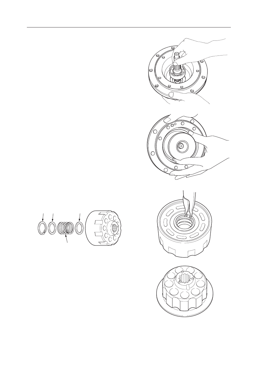
13. Mount the shaft on the flange holder.

• The bearing has been inserted and cannot be

disassembled.

• Be careful not to damage the oil seal by the

shaft.

14. Mount the balls and swash plate.

• Apply hydraulic oil to the sliding surfaces of

the swash plate.

15. Mount the retainer (6), spring (8) and retainer (7)

on the cylinder block and fix them with the snap
ring (9).

16. Fit the three pins to the cylinder block.

17. Install the friction disc.

C4D567

C4D568

K3D505

K3D506

8

7

6

9

K3D504

IV-197

HYDRAULIC UNITS

TRAVEL MOTOR

TB125, 135, 145

18. Mount the piston (12) and guide (13) on to the

shoe holder (11) to assemble the shoe holder
assembly.

19. Mount the shoe holder assembly on the cylinder

block to assemble the cylinder block assembly.

20. Install the center disc in the groove of the flange

holder.

21. Install the cylinder block assembly.

a. Install the shaft splinge in the guide.

K3D509

K3D508

K3D507

C4D572

11

13

12

IV-198

HYDRAULIC UNITS

TRAVEL MOTOR

TB125, 135, 145

22. Install the center disc in the groove of the flange

holder.

23. Mount two O-rings and two backup rings on the

brake piston.
• Be sure to position the backup rings on the

outer side.

24. Mount the brake piston assembly on the flange

holder.
• Apply grease to the O-ring and be careful not

to let it bite the seal.

25. Mount the valve plate on the valve body and

insert the springs into the spring holes.
• The dot in the figure shows the spring installa-

tion positions.

• Assemble the valve plate in such a manner that

the copper surface is on the cylinder block side.

• Apply grease to the valve plate and springs,

and be careful not to drop them.

C4D577

C4D578

K3D511

IV-199

HYDRAULIC UNITS

TRAVEL MOTOR

TB125, 135, 145

26. Supply 200 mL of hydraulic oil into the flange

holder and mount the valve body on the flange
holder.

27. Fix the valve body with a vise and tighten it with

the screws.
• Screw tightening torque:

51~65 N·m (5.2~6.6 kgf·m)

• Insert a protector such as an aluminum plate

between the flange holder and the vise to
prevent the outer surface of the body from
being damaged.

28. Install the plug.

• Seal tape should be wound around the threads

of the plug.

• Plug tightening torque:

26~31 N·m (2.7~3.2 kgf·m)

29. Mount the relief valve on the valve body.

• Relief valve tightening torque:

196~245 N·m (20~25 kgf·m)

C4D581

C4D582

G4D518

IV-200

HYDRAULIC UNITS

TRAVEL MOTOR

TB125, 135, 145

30. Mount the large and small O-ring on the body.

31. Mount the relief valve on the motor and tighten

them with the cap screws.
• Cap screw tightening torque:

25~32 N·m (2.6~3.3 kgf·m)

Reduction Gears

1. Install the bearing (17), snap ring (18) and bear-

ing (17) in the housing.
• Be careful of the installation direction of the

bearings.

2. Fit the O-ring to the floating seal and install them

in the housing.
• Apply grease to the O-ring.

G4D519

G4D520

C4D583

17

18

17

C4D584

C4D585

IV-201

HYDRAULIC UNITS

TRAVEL MOTOR

TB125, 135, 145

3. Fit the O-ring to the floating seal and install them

in the flange holder.
• Apply grease to the O-ring.

4. Mount the housing on the flange holder and fix

them with the snap ring.
• Tighten the housing of the reduction gear and

the flange of the hydraulic motor with a C-
clamp or hydraulic press, and fix them with the
snap ring.

5. Press fit the ring (1) to the gear B.

6. Install the needles (2) in the gear B.

• Apply grease to the needles to prevent from

coming off.

7. Press fit the ring (1) to the other end of the gear B.

8. Install the thrust washer, the gear B assembly (3),

the thrust washer and the pin (4).

9. Press fit the spring pins to secure the pins (4).

C4D588

K3D512

K3D513

K3D514

1

2

K3D515

4

3

IV-202

HYDRAULIC UNITS

TRAVEL MOTOR

TB125, 135, 145

10. Mount the gear S1 on the carrier and fix them with

the snap ring.

11. Mount the thrust washer, gear B2, needle and

thrust washer on the carrier 2 and fix them with
the snap ring.

12. Install the carrier 1 assembly in the housing.

13. Install the thrust washer and the carrier 2 assem-

bly in the housing.

K3D516

K3D517

C4D590

C4D591

IV-203

HYDRAULIC UNITS

TRAVEL MOTOR

TB125, 135, 145

14. Install the gear S2.

15. Fit the O-ring to the housing.

16. Supply 0.8 L of lubricant.

17. Install the ring on the cover.

• Apply grease to secure.

18. Install the cover on the housing.

• Line up the plug holes (G 3/8) with the cuts in

the housing.

K3D518

C4D595

G4D524

G4D525

IV-204

HYDRAULIC UNITS

TRAVEL MOTOR

TB125, 135, 145

19. Fit the snap ring to secure the cover.

• Put the blade of a screwdriver on the snap ring

end and push it into position.

20. Fit the O-rings to the plugs and install the plugs on

the cover.
• Plug tightening torque:

46~51 N·m (4.7~5.2 kgf·m)

21. Fit the O-ring to the plug and install the plug on

the cover.
• Plug tightening torque:

12~13 N·m (1.2~1.3 kgf·m)

INSPECTION AND ADJUSTMENT

“IV-165~166”

TROUBLESHOOTING

“IV-167~168”

G4D526

G4D527

G4D528

IV-205

HYDRAULIC UNITS

SLEW MOTOR

TB125, 135, 145

SLEW MOTOR (TB125)

CONSTRUCTION

Hydraulic Motor

  1. O-ring
  2. O-ring
  3. O-ring
  4. O-ring
  5. Disc
  6. Cylinder Block
  7. Brake Piston
  8. Spring
  9. Shaft

E5D600

16

23

19

9

13

28

20

6

22

15

8

24

10

12

17

14

18

11

7

26

3

4

2

1

21

5

25

10. Retainer
11. Disk Spring
12. Retainer
13. Guide
14. Pin
15. Valve Plate
16. Bearing
17. Snap Ring
18. Spring Seat

19. Shoe Holder
20. Pin
21. Orifice
22. Pin
23. Swash Plate
24. Bearing
25. Housing
26. Cover

IV-206

HYDRAULIC UNITS

SLEW MOTOR

TB125, 135, 145

Reduction Gears

  1. Plate
  2. Oil Seal
  3. Shaft
  4. Collar
  5. Bearing
  6. Housing

  7. Bearing
  8. Plate
  9. Collar
10. Carrier
11. Thrust Washer
12. Race

13. Needle
14. Planetary Gear
15. Thrust Plate
16. Drive Gear
17. O-ring
18. O-ring

IV-207

HYDRAULIC UNITS

SLEW MOTOR

TB125, 135, 145

Brake Valve

A: Relief Valve
B: Timer Valve
C: Check Valve

  1. O-ring
  2. Poppet
  3. O-ring
  4. O-ring
  5. Backup ring
  6. O-ring
  7. O-ring
  8. O-ring

E5D602

19

20

21

22

18

8

24

23

B

17

A

C

16

7

11

10

15

5

4

14

9

6

2

12

13

1

3

  9. Backup ring
10. Sleeve
11. Seat
12. Seat
13. Spring
14. Plug
15. Piston
16. Spring

17. O-ring
18. Sleeve
19. O-ring
20. O-ring
21. O-ring
22. Spool
23. Washer
24. Spring

IV-208

HYDRAULIC UNITS

SLEW MOTOR

TB125, 135, 145

OPERATION

Hydraulic Motor

9 pistons (2) are fitted in the cylinder block (1) and
there is a valve plate (3) with two half moon ports, B
and C in the end. Also, the cylinder block (1) rotates
freely and is joined to the shaft (4) via the spline. On
the other band, the swash plate (5) is fastened to the
housing.
When high pressure oil is introduced into port B, one
piston (2) makes contact and force F bears on the
swash plate (5).
F = P 

×

 A  P: Pressure  A: Piston Sectional Area

The force F which the piston (2) applies to the swash
plate (5) is divided into force F1, which pushes the
plate, and force F2, which rotates the cylinder block
(1). The total sum of the components in the direction
of rotation of the high pressure side piston generates
a rotational force in the cylinder block (1) and via the
spline, torque is transmitted to the shaft (4), turning it.
Conversely, if high pressure oil is introduced to port
C, rotation is the reverse of the above.

Relief Valve

Operation 1

When the Motor is Started
When the motor is started, since the inertial load is
great, the pressure of the oil required to accelerate it
rises. If this pressure reaches the relief valve set
pressure, the relief valve operates and oil returns to
port M2.
In this way, the motor begins to turn as it relieves the
relief valve, and as the rotational speed increases, the
amount of relief decreases until it stops.
In this way, the shock during starting is absorbed.

When the Motor is Stopped
When the motor is stopped, the return circuit is closed
off.
However, since the motor tends to want to continue
rotating due to inertial energy, the pressure in port M2
rises. When this pressure reaches the relief valve’s set
pressure, the relief valve operates and oil flows to port
M1. In this way, the flow of oil to port M1 prevents
cavitation from occurring as it absorbs the shock
during stopping.

E5D603

3

5

A

F1

F

F

F

B

VIEW A

C

F

F2

F2

F2

F2

4

2

1

M2

M1

T

E5D605

M2

M1

T

E5D606

IV-209

HYDRAULIC UNITS

SLEW MOTOR

TB125, 135, 145

Operation 2

Since this relief valve has a shockless mechanism, it
operates in 2 steps.
1st Step
When the relieving operation starts, the pressure P1 in
the chamber B is kept low, while the pressure P in the
chamber A becomes high due to the oil which flows
into it.
At this time, there are two forces acting on the poppet
(10), force (F), which attempts to move the poppet
(10) to the left and force (F1) which pushes against the
seat on the right side. Since F = P 

×

 A, F1 = P1 

×

 A1,

P > P1 and A > A1, the poppet (10) is moved to the left
by this force “F – F1”.
This opens a supply side circuit from chamber A and
lets the pressure escape. That is, during the time piston
(11) is moving to its stroke end, the relief valve
operates at low pressure.

2nd Step
When the piston (11) reaches the stroke end, the
pressure in chamber B rises and the pressures in
chamber A and chamber B equalize. At this time, the
force moving the poppet (10) to the left side becomes
“P = P1”, so this becomes “A – A1” and the relief
valve operates at the specified set pressure.

Timer Valve

This function is used to prevent sudden operation of
the parking brake when the motor is stopped.
At the time of parking brake operation, pressure oil
from the port P4 is supplied at all times to the port PG,
the valve spool (1) is pushed to the right by the force
of the spring (2), and the port PG is closed.
When turning pilot pressure or arm pilot pressure is
led to the port SH, the spool (1) is moved to the left
against the force of the spring (2), and the port PG is
opened. The pressure oil from the port PG passes
through the hole at the center of the spool (1) and is  led
to the parking brake release port (PB), so that the
parking brake is released.

When the pilot pressure at the port SH disappears, the
spool (1) is moved by the force of the spring (2) to the
right, the port PG is closed, and the oil in the brake
piston chamber (3) is prevented from escaping. The
oil in the chamber flows gradually through the orifice
(4) at the outer circumference of the spool (1) to the
drain port dr, so that the parking brake is not applied
rapidly, but after a certain time, just as if a timer were
used.

E5D610

1

2

SH

PB

PG

dr

E5D611

3

4

1

2

SH

PG

IV-210

HYDRAULIC UNITS

SLEW MOTOR

TB125, 135, 145

Parking Brake

The cylinder block (1) and disc (2) are connected via
a spline.
The disc (2) is pushed against the case (5) by the force
of the spring (3) via the brake piston (4) and brake
force is generated by the friction force between the
case (5) and the brake piston (4) stopping the cylinder
block (1) from turning.

When the oil is introduced from the parking brake
release port to the brake piston chamber (6), the oil
pressure overpowers the spring force and moves the
brake piston (4). This generates a clearance between
the case and the disc (2) to release the parking brake.

Reduction Gears

The drive gear (6) engages with the planetary gear (7)
and the planetary gear (7) engages with the ring gear
(8), which is integrated into the housing.
Driving force from the hydraulic motor is transmitted
from the drive gear (6) to the planetary gear (7), then
rotates the output shaft (10) via the planetary carrier
(9).

1

2

3

4

5

E5D608

2

6

4

E5D609

9

8

10

6

7

E5D604

IV-211

HYDRAULIC UNITS

SLEW MOTOR

TB125, 135, 145

E5D612

1

2

E5D613

3

4

5

6

7

8

E5D614

DISASSEMBLY AND ASSEMBLY

General Cautions

• Carry out disassembly and assembly operations in

a clean place and provide clean containers to place
the disassembled parts in.

• Before disassembly, clean around the ports and

remove the paint from each joint using a wire
brush.

• Wash the disassembled parts and dry them with

compressed air. Do not use a rag, as this could
cause clogging of dirt.

• Make match marks on each part so that they will be

assembled in the same positions when reassembled.

• Replace all seals with new ones each time the unit

is disassembled, coating them lightly with grease.

• Check each part to make sure there is no abnormal

wear or seizing and use sandpaper, etc. to remove
any burrs, sharp edges, etc.

Disassembly

Slew Motor

1. Remove the cap screws to disassemble the slew

motor into the hydraulic motor (1) and the reduc-
tion gear (2).
• Mark the mating position on both the hydraulic

motor and the reduction gear so that they can
be mated correctly when reassembling.

• Fix the hydraulic motor with a vise.

Brake Valve and Hydraulic Motor

1. Remove the cap screws and then the cover (3).

• Be careful not to drop the valve plate.

2. Remove the valve plate (4) and pin (5) from the

cover.

3. Remove the bearing (6), O-ring (7) and pin (8)

from the cover.


Content      ..     31      32      33      34     ..