Takeuchi compact excavator TB125, TB135, TB145 / diesel TNE / diesel Yanmar. Service Manual - page 35
 

  Index      Manuals     Takeuchi compact excavator TB125 (12510003~), TB135 (13510004~), TB145 (14510004~) / diesel TNE / diesel Yanmar. Service Manual


Search            copyright infringement  


Content      ..     33      34      35      36     ..


Takeuchi compact excavator TB125, TB135, TB145 / diesel TNE / diesel Yanmar. Service Manual - page 35


IV-228

HYDRAULIC UNITS

SLEW MOTOR

TB125, 135, 145

DISASSEMBLY AND ASSEMBLY

General Cautions

• Carry out disassembly and assembly operations in

a clean place and provide clean containers to place
the disassembled parts in.

• Before disassembly, clean around the ports and

remove the paint from each joint using a wire
brush.

• Wash the disassembled parts and dry them with

compressed air. Do not use a rag, as this could
cause clogging of dirt.

• Make match marks on each part so that they will be

assembled in the same positions when reassembled.

• Replace all seals with new ones each time the unit

is disassembled, coating them lightly with grease.

• Check each part to make sure there is no abnormal

wear or seizing and use sandpaper, etc. to remove
any burrs, sharp edges, etc.

Disassembly

Slew Motor

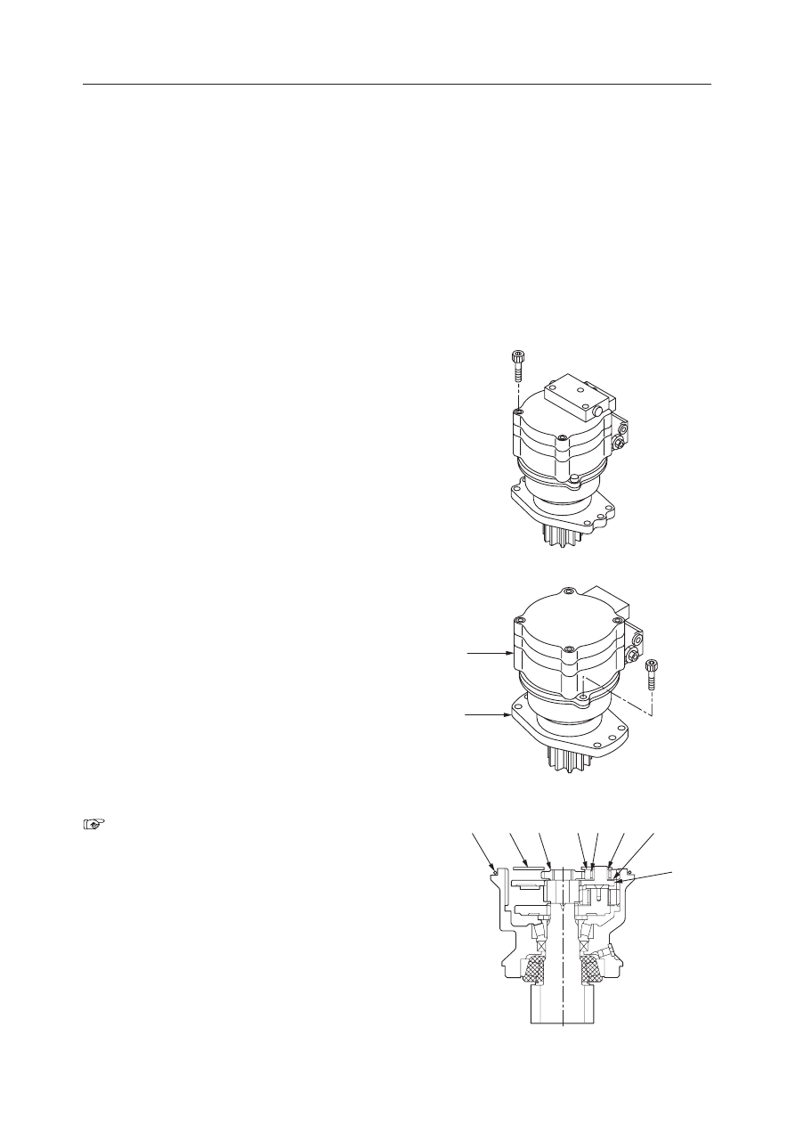
1. Remove the cap screws and then the anti-rebound

valve.

2. Remove the cap screws to disassemble the motor

into the hydraulic motor (1) and the reduction
gear (2).
• Mark the mating position on both the hydraulic

motor and the reduction gear so that they can
be mated correctly when reassembling.

• Fix the hydraulic motor with a vise.

Brake Valve and Hydraulic Motor

“IV-211~214”

Reduction Gears

1. Remove the O-ring (1) and thrust plate (2).

2. Remove the drive gear (3).

3. Remove the planetary gear A (4), needles (5),

inner race (6), and thrust washer (7) from the
carrier 1 (8).

4. Remove the carrier 1 (8).

G4D607

E5D612

1

2

G4D608

7

6

5

4

3

2

1

8

IV-229

HYDRAULIC UNITS

SLEW MOTOR

TB125, 135, 145

5. Remove the sun gear (12).

6. Remove the carrier 2 (13).

7. Remove the cap screws and then the thrust plate

(14) from the carrier 2 (13).
• Fix the carrier 2 with a vise.
• Loctite has been applied to the cap screws.

Warming the screws (for example, using a
portable drier) will make their removal much
easier.

8. Remove the planetary gear B (15), needles (16),

inner race (17) and thrust washer (18) from the
carrier 2 (13).

G4D609

12

G4D610

13

G4D611

14

13

G4D612

17

18

13

16

15

IV-230

HYDRAULIC UNITS

SLEW MOTOR

TB125, 135, 145

9. Remove the collar (9) and plate (10).

10. Remove the shaft (11) from the case.

• Be careful not to miss the shaft.
• If the shaft will not come out easily, lightly tap

it with a plastic hammer.

• To replacethe taper roller bearing or collar, the

case assembly should be replaced.

Anti-rebound Valve

1. Remove the plug (1) and then the spring (2).

2. Remove the check valve assembly (3).

3. Remove the sleeve (4).

4. Remove the plug (5) and then the orifice (6).

E5D626

9

10

E5D627

11

G4D613

3

1

2

3

4

2

1

G4D614

6

5

IV-231

HYDRAULIC UNITS

SLEW MOTOR

TB125, 135, 145

5. Remove the orifice (7), washer (8) and filter (9).

• The filter should be replaced with a new one

every time the anti-rebound valve is disas-
sembled.

Assembly

Anti-rebound Valve

1. Mount the filter (9), washer (8) and orifice (7) on

the body.
• Use a new filter.
• Orifice tightening torque: 4.9 N·m (0.5 kgf·m)

2. Mount the orifice (6) on the body.

• Orifice tightening torque:

2.45 N·m (0.25 kgf·m)

3. Fit the O-ring to the plug (5), and mount them on

the body.
• Plug tightening torque: 61.8 N·m (6.3 kgf·m)

G4D615

7

8

9

G4D615

7

8

9

G4D614

6

5

IV-232

HYDRAULIC UNITS

SLEW MOTOR

TB125, 135, 145

4. Mount the sleeve (4) on the body.

5. Mount the check valve assembly (3) and the

spring (2) on the body.

6. Fit the O-ring to the plug (1), and mount them on

the body.
• Plug tightening torque: 61.8 N·m (6.3 kgf·m)

Brake Valve and Hydraulic Motor

“IV-215~217”

Reduction Gears

1. Put grease into the inner race of the taper roller

bearing.
• Grease type: Shell ALVANIA Grease
• Grease volume: 17~20 mL

2. Mount the shaft (11) on the case.

3. Mount the plate (10) and collar (9).

G4D613

3

1

2

3

4

2

1

E5D629

E5D627

11

E5D626

9

10

IV-233

HYDRAULIC UNITS

SLEW MOTOR

TB125, 135, 145

4. Mount the thrust washer (18), inner race (17),

needles (16) and planetary gear B (15) on the
carrier 2 (13).

5. Mount the thrust plate (14) on the carrier 2 (13)

and fix them with the cap screws.
• Apply Loctite #242 to the cap screws.
• Cap screw tightening torque:

3.92 

±

0.49 N·m (0.4 

±

0.05 kgf·m)

6. Mount the carrier 2 (13) on the case.

7. Mount the sun gear (12).

G4D612

17

18

13

16

15

G4D611

14

13

G4D610

13

G4D609

12

IV-234

HYDRAULIC UNITS

SLEW MOTOR

TB125, 135, 145

8. Mount the carrier 1 (8).

9. Mount the thrust washer (7), inner race (6), needles

(5), planetary gear A (4), drive gear (3) and thrust
plate (2) on the carrier 1 (8).

Slew Motor

1. Unite the hydraulic motor (1) and the reduction

gear (2) and fix them with the cap screws.
• Cap screw tightening torque:

128 

±

7 N·m (13.1 

±

0.7 kgf·m)

2. Fit the O-ring to the cover.

3. Mount the anti-rebound valve on the cover and fix

them with the cap screws.
• Cap screw tightening torque:

29.4 

±

2 N·m (3.0 

±

0.2 kgf·m)

G4D608

7

6

5

4

3

2

1

8

E5D612

1

2

G4D607

IV-235

HYDRAULIC UNITS

SLEW MOTOR

TB125, 135, 145

INSPECTION AND ADJUSTMENT

Checking the Parts

“IV-220~221”

Anti-rebound Valve

Check Valve

• Scratches in sliding portions are deep or roughness is severe.
• The clearance with the body is large.
• Scratches in sliding portions are deep or seating is uneven.

Parts

Judgement Criteria

Treatment

• Scratches in sliding portions are deep or roughness is severe.
• There are scratches where oil leakage occurs.
• Damaged or severely deformed.

Body

Spring, Sleeve

• Replace
• Replace
• Replace
• Replace
• Replace
• Replace

IV-236

HYDRAULIC UNITS

SLEW MOTOR

TB125, 135, 145

TROUBLESHOOTING

“IV-222”

Anit-rebound Valve

The motor does not
rotate or its rota-
tion speed is slow.

Symptom

Probable Causes

Something other than the piston motor, valve
unit or anti-rebound valve is malfunctioning.

Inspect the pressure at the entrance of the
valve. Or, inspect individual units and ser-
vice as necessary.

Remedy

The check valve assembly is not seated prop-
erly.
• Foreign matter is trapped.

• The tightening torque of the anti-rebound

valve mounting bolt exceeds the prescribed
value.

• Remove the foreign matter. Repair or

replace the faulty parts.

• Use the prescribed tightening torque.

The sleeve is malfunctioning.
• Foreign matter is trapped.

• Remove the foreign matter. Repair or

replace the faulty parts.

The motor does not
stop or its stopping
speed is slow.

The check valve assembly is not seated prop-
erly.
• Foreign matter is trapped.

• The tightening torque of the anti-rebound

valve mounting bolt exceeds the prescribed
value.

• Remove the foreign matter. Repair or

replace the faulty parts.

• Use the prescribed tightening torque.

The valve within the check valve assembly is
malfunctioning.
• Foreign matter is trapped.

• Foreign matter is in the orifice of the valve.

• Remove the foreign matter. Repair or

replace the faulty parts.

• Remove the foreign matter.

The sleeve is malfunctioning.
• Foreign matter is trapped.

• Remove the foreign matter. Repair or

replace the faulty parts.

The valve within the check valve assembly is
malfunctioning.
• Foreign matter is trapped.

• Foreign matter is in the orifice of the valve.

• Remove the foreign matter. Repair or

replace the faulty parts.

• Remove the foreign matter.

Slewing stops with
a great shock.

The orifice is choked.
• Foreign matter is in the orifice of the anti-

rebound valve body.

• Foreign matter is in the orifice of the valve

unit.

• Remove the foreign matter.

• Remove the foreign matter.

IV-237

HYDRAULIC UNITS

SLEW MOTOR

TB125, 135, 145

  1. O-ring
  2. O-ring
  3. O-ring
  4. O-ring
  5. Friction Disc
  6. Cylinder Block
  7. Brake Piston
  8. Spring
  9. Shaft

SLEW MOTOR (TB145)

CONSTRUCTION

Hydraulic Motor

10. Retainer
11. Spring
12. Retainer
13. Guide
14. Pin
15. Valve Plate
16. Bearing
17. Snap Ring
18. Collar

19. Shoe Holder
20. Pin
21. O-ring
22. Center Disc
23. Swash Plate
24. Bearing
25. Housing
26. Pin
27. Piston

K3D6001

25

19

27

6

18

4

2

7

1

3

26

24

15

17
12

8

10

27

20

11

14

5

22

23

13

9

21

16

IV-238

HYDRAULIC UNITS

SLEW MOTOR

TB125, 135, 145

  1. Plate
  2. Oil Seal
  3. Shaft
  4. Collar
  5. Bearing
  6. Housing
  7. Bearing
  8. Plate
  9. Nut
10. Carrier 2

Reduction Gears

11. Ring Gear
12. Race
13. Needle
14. Planetary Gear
15. Thrust Plate
16. Drive Gear
17. O-ring
18. O-ring
19. Screw
20. Sun Gear

21. Carrier 1
22. Pin
23. Race
24. Needle
25. Planetary Gear A
26. Thrust Plate
27. Snap Ring
28. Collar

K3D601

3

4

8

1

18

2

9

17

11

20

27

21

23

24

25

26

22

6

5

28

7

10

12

13

14

15

19

16

IV-239

HYDRAULIC UNITS

SLEW MOTOR

TB125, 135, 145

Brake Valve

  1. O-ring
  2. Poppet
  3. O-ring
  4. O-ring
  5. Backup ring
  6. O-ring
  7. O-ring
  8. O-ring
  9. Backup ring
10. Sleeve
11. Seat
12. Seat

13. Spring
14. Plug
15. Piston
16. Spring
17. O-ring
18. Guide
19. O-ring
20. O-ring
21. O-ring
22. Guide
23. Washer
24. Spring

25. Body
26. Check Valve Assembly
27. Spring
28. Sleeve
29. Orifice
30. O-ring
31. Body
32. O-ring
33. Filter
34. Washer
35. Orifice
36. Backup ring

A: Relief Valve
B: Timer Valve
C: Check Valve
D: Anti-rebound Valve

37. Backup ring
38. Backup ring
39. Cover
40. Spring
41. Poppet
42. Body
43. Valve
44. Filter
45. Orifice
46. Orifice

K3D602

D

25

28

26

27

30

29

30

A

B

C

46

44

43

42

21

24

23

45

20

41

40

8

32

31

35

34

33
32

32

39

18

19

38

15

22

16

12

10

11

7

17 2 37 6 13

4 36 1 9

3

5

14

IV-240

HYDRAULIC UNITS

SLEW MOTOR

TB125, 135, 145

OPERATION

Hydraulic motor

“IV-208”

Relief Valve

“IV-208~209”

Anit-rebound Valve

“IV-226”

Timer Valve

This function is used to prevent sudden operation of
the parking brake when the motor is stopped.
At the time of parking brake operation, pressure oil
from the port P4 is supplied at all times to the port PG,
the valve spool (1) is pushed to the right by the force
of the spring (2), and the port PG is closed.
When turning pilot pressure or arm pilot pressure is
led to the port SH, the spool (1) is moved to the left
against the force of the spring (2), and the port PG is
opened. The pressure oil from the port PG passes
through the hole at the center of the spool (1) and is  led
to the parking brake release port (PB), so that the
parking brake is released.

When the pilot pressure at the port SH disappears, the
spool (1) is moved by the force of the spring (2) to the
right, the port PG is closed, and the oil in the brake
piston chamber (3) is prevented from escaping. The
oil in the chamber flows gradually through the ori-
fices (4), (5) in the spool (1) to the drain port dr, so that
the parking brake is not applied rapidly, but after a
certain time, just as if a timer were used.

Parking brake

The friction discs (2) are connected to the housing and
the center discs (1) are connected to the cylinder block
(3) via the spline, respectively. The center discs (1)
and friction discs (2) are pressed against the housing
(6) by the springs (4) via the brake piston (5). The
friction force between these discs generates the brake
torque to prevent the cylinder block (3) from rotating.

When the pressure oil is introduced into the motor, the
oil flows from the parking brake release port (7) into
the brake piston chamber (8). The oil pressure over-
powers the spring force and moves the brake piston

K3D607

1

2

PG

PB

SH

K3D608

1

2

5

4

3

PG

K3D605

6

5

4

3

2

1

IV-241

HYDRAULIC UNITS

SLEW MOTOR

TB125, 135, 145

(5) to the right. This generates a clearance between the
center discs (1) and friction discs (2) to release the
parking brake. When the motor stops, the spool re-
turns to the neutral position to close the parking brake
release port (7). The pressure oil in the brake piston
chamber (8) is introduced into the motor case and the
spring (4) operates the parking brake.

Reduction Gears

“IV-227”

IV-242

HYDRAULIC UNITS

SLEW MOTOR

TB125, 135, 145

DISASSEMBLY AND ASSEMBLY

Table of Special Tools

JIG (A)

NAME, DIMENSIONS

NAME, DIMENSIONS

JIG (F)

1

6

JIG (B)

JIG (G)

2

7

JIG (C)

JIG (H)

3

8

JIG (D)

JIG ( I )

4

9

JIG (E)

JIG (J)

5

10

Unit: mm

IV-243

HYDRAULIC UNITS

SLEW MOTOR

TB125, 135, 145

JIG (K)

NAME, DIMENSIONS

NAME, DIMENSIONS

JIG (O)

11

15

JIG (L)

12

JIG (M)

13

JIG (N)

14

Unit: mm

JIG (P)

16

JIG (Q)

17

Gear type

Tooth

Module

Pressure angle

No. of teeth

A: Adjust the internal gear so that a

clearance of 0.3 to 0.5 mm is
produced when the male gear
(shown in the table) is inserted.

B: Width across flat

Profile shifted gear

Standard gear tooth

6.5

20

°

14

Diameter of standard pitch circle

Amount of addendum modification

Height of tooth

Addendum circle diameter

Dedendum circle diameter

ø 91.000

1.95

14.625

ø 107.9

ø 78.65


Content      ..     33      34      35      36     ..