Takeuchi compact excavator TB125, TB135, TB145 / diesel TNE / diesel Yanmar. Service Manual - page 10
 

  Index      Manuals     Takeuchi compact excavator TB125 (12510003~), TB135 (13510004~), TB145 (14510004~) / diesel TNE / diesel Yanmar. Service Manual


Search            copyright infringement  


Content      ..     8      9      10      11     ..


Takeuchi compact excavator TB125, TB135, TB145 / diesel TNE / diesel Yanmar. Service Manual - page 10


III-58

MACHINE CONFIGURATION

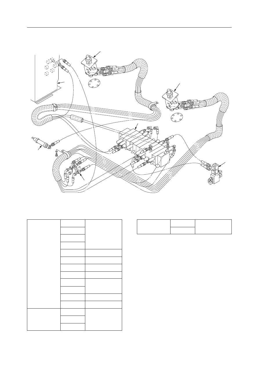
CONTROL SYSTEM

TB125, 135, 145

TB145

A Type (ISO)

 Table of Connections 

Pilot Valve

Control Valve

R1

Pb1

R2

Pa2

R3

Pa1

R4

Pb2

RP

H2

RT

T1

L1

C2

L2

Pb7

L3

A2

L4

B2

LP

Pp

LT

T2

C1

Pa8

A1

Pb8

B1

Pa7

Lock Cylinder

Tank

Shuttle Valve

Control Valve

  1. Right Pilot Valve
  2. Left Pilot Valve
  3. Solenoid Valve
  4. Control Valve
  5. Hydraulic Tank
  6. Shuttle Valve
  7. Lock Cylinder

Shuttle Valve

Control Valve

Tank

Control Valve

Shuttle Valve

A

Pa6

B

Pb6

Control Valve

Solenoid Valve

L1

L2

L3

L4

LT

LP

R1

R2

R3

R4

RT

RP

A

B

H2

B2

C2

A2

A1

C1

B1

Pp

Pb8

Pa8

Pa7

Pa6

Pa1

Pa2

Pb7

Pb6

Pb2

Pb1

T2

T1

5

1

2

3

4

6

7

K3C500

III-59

MACHINE CONFIGURATION

CONTROL SYSTEM

TB125, 135, 145

A Type (ISO) 

 G Type (JCB)

 Table of Connections 

Pilot Valve

Control Valve

Selector Valve

Control Valve

Selector Valve

Lock Cylinder

Tank

Shuttle Valve

Selector Valve

Shuttle Valve

Selector Valve

Control Valve

Tank

R1

Pb1

R2

1

R3

Pa1

R4

2

RP

H2

RT

T1

L1

C2

L2

3

L3

A2

L4

4

LP

Pp

LT

T2

C1

Pa8

A1

Pb8

B1

Pa7

A

Pa6

B

Pb6

A

Pa2

B

Pb2

C

Pb7

D

B2

Shuttle Valve

  1. Right Pilot Valve
  2. Left Pilot Valve
  3. Solenoid Valve
  4. Control Valve

  5. Hydraulic Tank
  6. Shuttle Valve
  7. Selector Valve
  8. Lock Cylinder

Solenoid Valve

Shuttle Valve

Selector Valve

Control Valve

Selector Valve

Position

A Type (ISO)

Position

G Type (JCB)

Right Pilot Valve

Boom

Bucket

Arm

Slew

Lower

Raise

Load

Dump

Dump

Load

Left

Right

Arm

Bucket

Boom

Slew

Dump

Load
Load

Dump

Lower

Raise

Left

Right

Front

Rear

Left

Right

Front

Rear

Left

Right

Left Pilot Valve

L1

L2

L3

L4

LT

LP

R1

R2

R3

R4

RT

RP

2

C

1

4

D

3

A

B

A

B

H2

B2

C2

A2

A1

C1

B1

T2

T1

Pp

Pb8

Pa8

Pa7

Pa6

Pa1

Pa2

Pb7

Pb6

Pb2

Pb1

5

1

2

3

4

6

8

K3C501

7

III-60

MACHINE CONFIGURATION

CONTROL SYSTEM

TB125, 135, 145

Lever Stand (Cab)

  1. Control Box R
  2. Control Box L
  3. Plate

  4. Lever
  5. Pilot Valve
  6. Gas Spring

Lever Stand (Canopy)

  1. Control Box R
  2. Control Box L
  3. Plate
  4. Plate

  5. Lever
  6. Lever
  7. Bracket
  8. Bracket

  9. Lever
10. Gas Spring
11. Safety Switch
12. Pilot Valve

  7. Safety Switch
  8. Bracket
  9. Lever

III-61

MACHINE CONFIGURATION

CONTROL SYSTEM

TB125, 135, 145

Dozer Blade Lever

NOTES:
• When assembling, apply grease to the inside of the DU bushing.

  1. Bracket
  2. Lever
  3. Cover

  4. Control Cable
  5. Yoke

G4C503

5

4

1

2

3

5

III-62

MACHINE CONFIGURATION

CONTROL SYSTEM

TB125, 135, 145

DISASSEMBLY AND ASSEMBLY

Removing the Lever Stand

1. Disconnect the battery ground cable from the [-]

terminal of the battery.

2. Remove the cab.

“Removing the Cab”

3. Remove the lever stand L.

a. Remove the cover (1).
b. Pull up the lock lever (2) and raise the lever

stand. Then pull off the pin and remove the
lock lever (2).

c. Remove the cover (3).
d. Disconnect the hydraulic hoses (4) from the

pilot valve.
• Attach identification labels to individual

hoses for correct reassembling.

e. Disconnect the electric wiring of the limit

switch.

f. Take out the gas spring (12) and pin (13), and

remove the control box.

4. Remove the lever stand R.

a. Remove the cover, and disconnect the control

cable (6) from the blade lever.

b. Remove the bracket (7) from the lever stand.
c. Remove the covers (8).
d. Pull up the lock lever (9) and raise the lever

stand. Then pull off the pin and remove the
lock lever (9). (For canopy type)

e. Remove the cover (10).
f. Disconnect the electric wiring.
g. Disconnect the hydraulic hoses (11) from the

pilot valve.
• Attach identification labels to individual

hoses for correct reassembling.

h. Take out the gas spring (12) and pin (13), and

remove the control box. (For canopy type)

i. Take out the socket bolts, and remove the

control box. (For cab type)

Installing the Lever Stand

Follow the same procedure as for removal in the
reverse order.

G4C504

1

3

2

G4C505

4

12

13

G4C506

8

9

10

7

6

G4C507

11

12

13

III-63

MACHINE CONFIGURATION

CONTROL SYSTEM

TB125, 135, 145

INSPECTION AND ADJUSTMENT

Adjusting Stroke

Adjust the lever’s stroke to correspond to the control
valve spool stroke using the setscrew.

1. The control valve’s spool should be in the neutral

position.

2. Turn the rod and position the lever in the center of

the stroke, then fasten the rod with the nut.

3. Move the lever and hold it at the stroke end of the

valve spool.

4. Set the setscrew.

G4C508

III-64

MACHINE CONFIGURATION

CONTROL SYSTEM

TB125, 135, 145

III-65

MACHINE CONFIGURATION

ATTACHMENTS

TB125, 135, 145

ATTACHMENTS

CONSTRUCTION

  1. Bucket
  2. Bucket Link
  3. Guide Link R
  4. Guide Link L
  5. Bucket Cylinder
  6. Arm
  7. Arm Cylinder

  8. Boom
  9. Boom Cylinder
10. Swing Bracket
11. Swing Cylinder
12. Dozer Blade Cylinder
13. Dozer Blade

G4C600

11

7

8

9

10

12

6

5

3

4

1

13

2

III-66

MACHINE CONFIGURATION

ATTACHMENTS

TB125, 135, 145

Removing the Bucket

• Move the back side of the bucket so that it is

down, then lower it fully to the ground.

1. Take out the lock bolt (1) and remove the pin (2).

2. Take out the lock bolt (1) and remove the pin (3).

3. Remove the bucket.

• Standard bucket mass:

TB125…55 kg, TB135…73 kg, TB145…115 kg

Installing the Bucket

Follow the procedure used for removal in reverse
order.

• Position the O-ring at the “A” position on the

outer perimeter of the bucket bush before
mounting the bucket. Upon completion of the
mounting, move the O-ring to the prescribed
“B” position.

0.5~1.0mm

C4C601

A

B

C4C603

1

3

2

1

G4C601

DISASSEMBLY AND ASSEMBLY

General Cautions

• When disconnecting hydraulic hoses, be sure to

bleed off any residual pressure in the hoses and in
the Hydraulic Tank.

• Plug openings which are opened up when piping is

disconnected to prevent dust and mud, etc. from
getting in.

• During assembly, be sure to adjust all the parts with

shims so that there will be no looseness in the
mounts.

• When aligning pin hole positions, absolutely do

not insert a finger in any pin holes.

• When all the hydraulic equipment such as hydrau-

lic cylinders and piping have been removed and the
hydraulic cylinders are being operated for the first
time after reassembly, be sure the bleed the air out
of the hydraulic circuits by the following proce-
dure.

• Keep the clearance at the pin connecting section to

0.5 mm or less by using the shim.

Air Bleeding Operation

1. Start the engine and let it idle for about 5 minutes.
2. With the engine running at slow speed, extend

and retract the cylinders 4 or 5 times.
• Move the piston rods to a position 100 mm

before the end of the stroke, taking care not to
allow any relief whatsoever.

3. Perform the operation in (2) with the engine at top

speed, then with the engine at slow speed, move
the piston rods to the stroke end, allowing relief.

III-67

MACHINE CONFIGURATION

ATTACHMENTS

TB125, 135, 145

2

6

1

3

5

4

C4C604

5

6

8

7

9

C4C606

G4C602

2

4

1

3

Removing the Link

• Fully retract the bucket cylinder and lower the

front end of the arm to the ground.

1. Take out the split pin, then remove the castle nut

(1).

2. Suspend the bucket link (2) temporarily and take

out the pin (3).
• Place pillow blocks under the bucket cylinder

to support it.

• Since the end of the guide link will drop when

the pin is taken out, exercise caution.

3. Take out the pin (4), then remove the guide link L

(5), R (6).

Installing the Link

Follow the procedure used for removal in reverse
order.

Removing the Arm

1. Disconnect the hydraulic hoses (1) from the bucket

cylinder (2). Next, disconnect hydraulic hoses
from the auxiliary ports (3).

2. Suspend the bucket cylinder (2) temporarily, take

out the pin (4) and remove the bucket cylinder.
• Bucket cylinder mass:

TB125…16 kg, TB135…24 kg, TB145…34 kg

3. Place pillow blocks under the arm cylinder (5),

then take out the pin (6).

4. Take out the split pin and remove the castle nut

(7).

5. Suspend the arm (8) temporarily, take out the pin

(9) and remove the arm.
• Arm mass:

TB125…45 kg, TB135…66 kg, TB145…94 kg

Installing the Arm

Follow the procedure used for removal in reverse
order.

III-68

MACHINE CONFIGURATION

ATTACHMENTS

TB125, 135, 145

2

3

C4C607

1

9

4

5

8

6

7

10

C4C608

Removing the Boom

• Lower the front end of the boom so that it is in

full contact with the ground.

1. Disconnect the hydraulic hoses (1) from the arm

cylinder (2).

2. Suspend the arm cylinder (2) temporarily, then

take out the pin (3) and remove the arm cylinder.
• Arm cylinder mass:

TB125…25 kg, TB135…33 kg, TB145…51 kg

3. Remove the clamp (4) from the boom (5), and

disconnect the hydraulic hose (6) from the boom
cylinder (7).

4. Suspend the boom cylinder (7) temporarily and

take out the pin (8).

5. Disconnect the wiring to the boom light.

6. Disconnect the hydraulic hoses (9) from the pipes.

7. Suspend the boom (5) temporarily, take out the

pin (10) and remove the boom.
• Boom mass:

TB125…98 kg, TB135…122 kg, TB145…188 kg

Installing the Boom

Follow the procedure used for removal in reverse
order.

III-69

MACHINE CONFIGURATION

ATTACHMENTS

TB125, 135, 145

C4C609

4

7

3

1

5

6

2

Removing the Swing Bracket

1. Suspend the boom cylinder (1) temporarily, take

off the pin (2) and remove the boom cylinder.
• Boom cylinder mass:

TB125…27 kg, TB135…40 kg, TB145…62 kg

2. Remove the cover (3) from the swing bracket (4).

3. Take out the pin (5) and disconnect the swing

cylinder (6) from the swing bracket (4).

4. Suspend the swing bracket (4) temporarily, take

out the pin (7), and remove the swing bracket.
• Be careful not to damage the hoses.
• Swing bracket mass:

TB125…63 kg, TB135…74 kg, TB145…115 kg

Installing the Swing Bracket

Follow the same procedure as for removal in the
reverse order.

III-70

MACHINE CONFIGURATION

ATTACHMENTS

TB125, 135, 145

3

1

2

4

1

C4C610

5

6

C4C611

Removing the Dozer blade

• Lower the dozer blade fully to the ground.

1. Disconnect the hydraulic hoses (1) from the dozer

blade cylinder (2).

2. Suspend the dozer blade cylinder (2) temporarily,

take out the pins (3), (4) and remove the cylinder.
• Dozer blade cylinder mass:

TB125…21 kg, TB135…35 kg, TB145…41 kg

3. Suspend the dozer blade (5) temporarily, take out

the pins (6), and remove the dozer blade.
• Dozer blade mass:

TB125…126 kg, TB135…149 kg, TB145…196 kg

Installing the Dozer Blade

Follow the procedure used for removal in reverse
order.

III-85

MACHINE CONFIGURATION

HYDRAULIC SYSTEM

TB125, 135, 145

CONSTRUCTION

Hydraulic Tank

TB125, TB135

A: Tightening Torque: 47 N·m (4.8 kgf·m) [Apply thread lock]

  1. Tank
  2. Cover
  3. Suction Pipe
  4. Plate
  5. Spring
  6. Check Valve
  7. Suction Filter

  8. Return Filter
  9. Plug
10. O-ring
11. Sight Gauge
12. O-ring
13. O-ring

9 · 10

2 · 12

9 · 10

5

6

8

4

A

11

7

3 · 13

9 · 10

A

1

G4C701

III-86

MACHINE CONFIGURATION

HYDRAULIC SYSTEM

TB125, 135, 145

TB145

A: Tightening Torque: 47 N·m (4.8 kgf·m) [Apply thread lock]

  1. Tank
  2. Cover
  3. Suction Pipe
  4. Plate
  5. Spring
  6. Check Valve
  7. Suction Filter

  8. Return Filter
  9. Plug
10. O-ring
11. Sight Gauge
12. O-ring
13. O-ring

2 · 12

9 · 10

9 · 10

4

5

6

8

11

7

3 · 13

9 · 10

A

A

1

K3C701

III-87

MACHINE CONFIGURATION

HYDRAULIC SYSTEM

TB125, 135, 145

Function

1. This tank stores the quantity of hydraulic oil

necessary to operate the cylinders and hydraulic
motors.

2. It keeps air, moisture and dirt out of the hydraulic

oil.

3. It dissipates heat and lowers the oil temperature.

4. Volume of Hydraulic Oil.

Check the oil level with the arm cylinder and
bucket cylinder both fully retracted and with the
bucket and dozer blade both lowered to the ground.

Reference

If the amount of hydraulic oil is insufficient, the
disturbances in the flow of oil can not be calmed, and
this will result in air bubbles getting in the hydraulic
oil. If these bubbles are sucked into the hydraulic
pumps, they could cause cavitation. Heat  dissipation
time would also become shorter and would result in a
rise in the oil temperature.
If more than the specified amount of hydraulic oil is
supplied, the amount of air in the tank will become
small and changes in the oil level could cause the
pressure fluctuation in the tank to become severe.


Content      ..     8      9      10      11     ..