Takeuchi compact excavator TB125, TB135, TB145 / diesel TNE / diesel Yanmar. Service Manual - page 9
 

  Index      Manuals     Takeuchi compact excavator TB125 (12510003~), TB135 (13510004~), TB145 (14510004~) / diesel TNE / diesel Yanmar. Service Manual


Search            copyright infringement  


Content      ..     7      8      9      10     ..


Takeuchi compact excavator TB125, TB135, TB145 / diesel TNE / diesel Yanmar. Service Manual - page 9


III-42

MACHINE CONFIGURATION

UPPER FRAME

TB125, 135, 145

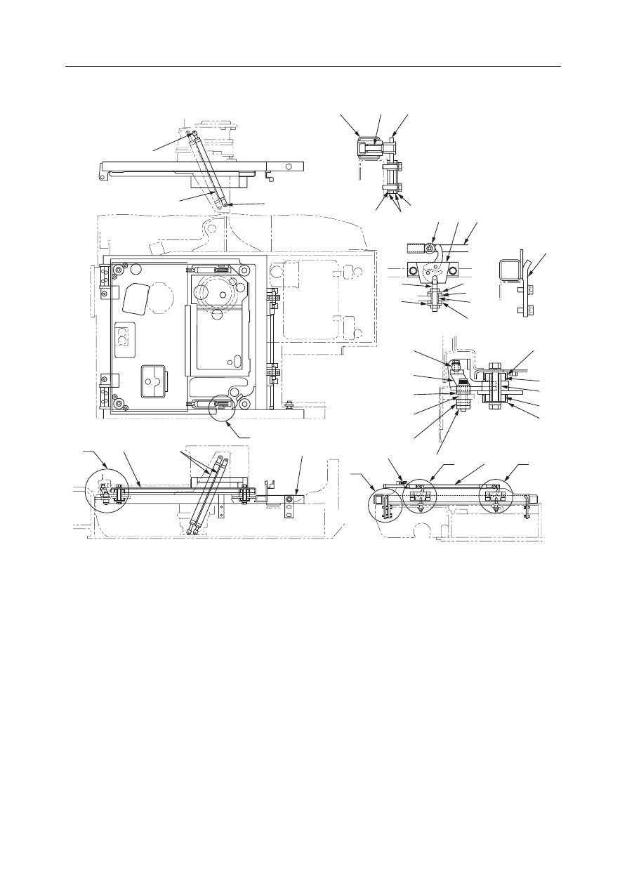
Floor Frame

  1. Floor Frame
  2. Floor Plate
  3. Hinge
  4. Shaft
  5. Rod
  6. Lock Bolt
  7. Nut Plate
  8. Pin
  9. Spacer

10. Spacer
11. Spacer
12. Spacer
13. Cushion
14. Cushion
15. Washer Plate
16. Nut Plate
17. Side Stopper
18. Rubber

19. Cover
20. Hook
21. Collar
22. Lock Assembly
23. Pin
24. Spring
25. Stay Damper

G4C400

7

6

1

10

13

15

23

25

8

17

21 22

5

15

13

9

13

20

15

19

18

12
18

19

4

3

14

11

14

16

5

24

C

D

D

B

A

2

1

25

DETAIL C

DETAIL D

DETAIL B

DETAIL A

III-43

MACHINE CONFIGURATION

UPPER FRAME

TB125, 135, 145

Covers

TB125, TB135

  1. Engine Hood
  2. Front Cover
  3. Side Cover L
  4. Side Cover R
  5. Under Cover
  6. Bracket
  7. Bracket

  8. Hinge Pin (TB135 only)
  9. Center Cover (TB135 only)
10. Collar
11. Wire
12. Stay Damper
13. Link (TB125 only)
14. Link (TB125 only)

G4C401

11

8

10

7

DETAIL A

DETAIL B

DETAIL C

< TB125 >

< TB135 >

< TB135 >

DETAIL E

DETAIL D

6

6

A

C

A

D

5

E

4

9

1

3

12

2

B

13

< TB125 >

14

< TB125 >

III-44

MACHINE CONFIGURATION

UPPER FRAME

TB125, 135, 145

TB145

  1. Engine Hood
  2. Front Cover
  3. Side Cover L
  4. Side Cover R
  5. Front Cover L
  6. Center Cover
  7. Under Cover

  8. Bracket
  9. Bracket
10. Bracket
11. Hinge Pin
12. Collar
13. Wire
14. Stay Damper

K3C401

9

10

12

11

13

8

5

DETAIL A

DETAIL B

DETAIL C

DETAIL D

DETAIL E

C

A

D

A

7

E

4

6

B

5

2

3

14

1

VIEW F

F

III-45

MACHINE CONFIGURATION

UPPER FRAME

TB125, 135, 145

Canopy

  1. Front Pole
  2. Rear Pole
  3. Engine Cover
  4. Roof

A: Apply thread lock.

G4C402

A

1

3

2

A

A

4

A

A

III-46

MACHINE CONFIGURATION

UPPER FRAME

TB125, 135, 145

Cab

  1. Main Body
  2. Front Sash
  3. Door
  4. Side Sash
  5. Front Glass
  6. Glass R
  7. Glass L
  8. Rear Glass
  9. View Roof

10. Plate
11. Cover
12. Plate
13. Plate
14. Plate
15. Stopper R
16. Stopper L
17. Lock Assembly

G4C403

D

D

4

6

F

1

2

5

A

B

8

7

3

C

C

13

17

11

10

12

VIEW F

SECTION A-A

SECTION B-B

SECTION C-C

SECTION E-E

SECTION D-D

A

B

15·16

14

E

E

9

III-47

MACHINE CONFIGURATION

UPPER FRAME

TB125, 135, 145

DISASSEMBLY AND ASSEMBLY

Removing the Upper Frame

1. Remove the hoe attachment.

“Attachments, Disassembly and Assembly”

2. Remove the canopy or cab.

“Removing the Cab”

3. Remove the engine hood, front cover, and side

cover R, L.

“Removing the Covers”

4. Tilt the floor and install safety stoppers.

5. Disconnect the hydraulic hoses (1) from the swivel

joint.
• Make match marks on the installation position

of the hoses before disconnecting them.

6. Take out the fixing bolts and remove the stopper

(2).
• Tightening torque:

102 

±

5.1 N·m (10.4 

±

0.52 kgf·m)

• Apply thread lock to the bolts.

7. Disconnect the grease pipe (3) from the slew

bearing.

8. Remove the safety stoppers and lower the floor

frame.

9. Remove the fixing bolts (7) from the outer race of

the slew bearing, leaving only two bolts each on
the front and the rear of the machine.
• When mounting the slew bearing, be careful of

the positions of the grease hole and reamer
bolts.

“Installing the Slew Bearing”

• Tightening torque:

TB125, TB135…102 

±

5.1 N·m (10.4 

±

0.52 kgf·m)

TB145…256 N·m (26.1 kgf·m)

• Apply molybdenum disulfide grease to the

threads and the bolt holes.

10. Suspend the upper frame temporarily and remove

the remaining fixing bolts while keeping the
frame well balanced.

11. Suspend the upper frame and remove it.

7

C4C405

1

2

G4C404

G4C405

3

III-48

MACHINE CONFIGURATION

UPPER FRAME

TB125, 135, 145

Installing the Upper Frame

Follow the same procedure as for removal in the
reverse order.

III-49

MACHINE CONFIGURATION

UPPER FRAME

TB125, 135, 145

Removing the Floor Frame

1. Disconnect the battery ground cable from the

battery.

2. Remove the canopy or cab.

“Removing the Cab”

3. Disconnect the accelerator wire (2) on the engine

side.
• After disconnecting the wire end from the wire

stopper, loosen the fastening nut and take it out
of the bracket.

4. Tilt up the floor frame and suspend it temporarily.

5. Disconnect the electric wiring from the control

box L.

“Removing the Lever Stand”

6. Remove the control unit (7).

a. Remove two mounting bolts (8) from the top of

the control unit.

b. Remove the mounting bolts (9) and (10) from

the plate (11) at the bottom of the control unit.

c. Remove the mounting bolt (12) and then the

clamp.

d. Pull out the control unit (7) together with the

plate (11), and disconnect the electric wiring.

7. Disconnect all hydraulic lines and electric wires

passing through the floor at the turntable side.
• Label all lines and wires to identify for correct

installation.

8. Disconnect the control cable (3) on the swing

pedal.
• After disconnecting the wire end from the wire

stopper, loosen the fastening nut and take it out
of the bracket.

9. Remove the stay damper (4).

10. Take out the bolts, then take out the shaft (5).

11. Suspend the floor frame (6) to remove it.

Installing the Floor Frame

Follow the procedure used for removal in reverse
order.

G4C408

5

5

6

G4C406

2

E5C406

8

7

8

12

10 11

9

9

8

III-50

MACHINE CONFIGURATION

UPPER FRAME

TB125, 135, 145

G4C409

4

1

3

2

G4C410

6

G4C411

8

7

5

Removing the Covers

1. Disconnect the battery ground cable from the

battery.

2. Remove the engine hood (1).

a. Open the engine hood and suspend it tempo-

rarily.

b. Disconnect the electric wiring (2) of the tail-

light.

c. Remove the stay damper (3).

3. <TB135, TB145 only> Remove the center cover

(4).

4. Remove the side cover R (5) and L (6).

5. Remove the installation bolts, disconnect the

wire (7) and the light’s electrical wiring, then
remove the front cover (8).

6. Remove the undercover.

Installing the Covers

Follow the same procedure as for removal in the
reverse order.

III-51

MACHINE CONFIGURATION

UPPER FRAME

TB125, 135, 145

G4C412

3

1

2

G4C413

2

2

G4C414

4

G4C415

Removing the Cab

1. Disconnect the battery ground cable from the

battery.

2. Disconnect the electric wiring (1) for the cab.

3. Remove the nuts (2) for installing the cab [at two

places each on the front and rear].

4. Take out the wing bolts (3) and remove the cover.

5. Suspend the cab and remove it.

• Cab mass: Approx. 200 kg.

Installing the Cab

Follow the procedure used for removal in reverse
order.

• The cab installation bolts (4) should be set in

the upper frame in advance.

• Suspend the cab temporarily, keeping it level,

and fasten it temporarily while it is still sus-
pended.

III-52

MACHINE CONFIGURATION

UPPER FRAME

TB125, 135, 145

III-53

MACHINE CONFIGURATION

CONTROL SYSTEM

TB125, 135, 145

CONTROL SYSTEM

CONSTRUCTION

Travel, Swing Lever Unit

NOTES:
• When assembling, apply grease to the inside of the DU bushing.
• Apply thread lock to the screws on the rod ends.

A: Details of the pedal mounting section
B: Details of the rod end tightening section
C: Applying thread lock

  1. Lever Bracket
  2. Right Travel Lever
  3. Left Travel Lever
  4. Bracket R
  5. Bracket L
  6. Plate
  7. Lever

  8. Lever
  9. Swing Pedal
10. Bracket
11. Lever
12. Control Cable
13. Lock Cylinder

III-54

MACHINE CONFIGURATION

CONTROL SYSTEM

TB125, 135, 145

Hydraulic Pilot Unit

TB125, TB135: S/N 13510004~13512532

A Type (ISO)

 Table of Connections 

Pilot Valve

Control Valve

R1

Pb9

R2

Pa8

R3

Pa9

R4

Pb8

RP

H2

RT

T2

L1

A2

L2

Pb5

L3

C2

L4

B2

LP

Pp

LT

T1

C1

Pa2

A1

Pb2

B1

Pa5

Lock Cylinder

Tank

Shuttle Valve

Control Valve

  1. Right Pilot Valve
  2. Left Pilot Valve
  3. Solenoid Valve
  4. Control Valve
  5. Hydraulic Tank
  6. Shuttle Valve
  7. Lock Cylinder

Shuttle Valve

Control Valve

Solenoid Valve

Control Valve

Shuttle Valve

A

Pa3

B

Pb3

Control Valve

Solenoid Valve

III-55

MACHINE CONFIGURATION

CONTROL SYSTEM

TB125, 135, 145

TB125, TB135: S/N 13510004~13512532

A Type (ISO) 

 G Type (JCB)

 Table of Connections 

Pilot Valve

Control Valve

Selector Valve

Control Valve

Selector Valve

Lock Cylinder

Tank

Shuttle Valve

Selector Valve

Shuttle Valve

Selector Valve

Control Valve

Solenoid Valve

R1

Pb9

R2

1

R3

Pa9

R4

2

RP

H2

RT

T2

L1

A2

L2

3

L3

C2

L4

4

LP

Pp

LT

T1

C1

Pa2

A1

Pb2

B1

Pa5

A

Pa3

B

Pb3

A

Pa8

B

Pb8

C

Pb5

D

B2

Shuttle Valve

Selector Valve

Position

A Type (ISO)

Position

G Type (JCB)

Right Pilot Valve

Boom

Bucket

Arm

Slew

Lower

Raise

Load

Dump

Dump

Load

Left

Right

Arm

Bucket

Boom

Slew

Dump

Load
Load

Dump

Lower

Raise

Left

Right

Front

Rear

Left

Right

Front

Rear

Left

Right

Left Pilot Valve

  1. Right Pilot Valve
  2. Left Pilot Valve
  3. Solenoid Valve
  4. Control Valve

  5. Hydraulic Tank
  6. Shuttle Valve
  7. Lock Cylinder
  8. Selector Valve

Solenoid Valve

Selector Valve

Control Valve

Shuttle Valve

III-56

MACHINE CONFIGURATION

CONTROL SYSTEM

TB125, 135, 145

TB135: S/N 13512533~

A Type (ISO)

 Table of Connections 

Pilot Valve

Control Valve

R1

Pb9

R2

Pa8

R3

Pa9

R4

Pb8

RP

H2

RT

T2

L1

A2

L2

Pb5

L3

C2

L4

B2

LP

PB2

LT

T1

C1

Pa2

A1

Pb2

B1

Pa5

Lock Cylinder

Tank

Shuttle Valve

Control Valve

  1. Right Pilot Valve
  2. Left Pilot Valve
  3. Solenoid Valve
  4. Control Valve
  5. Hydraulic Tank
  6. Shuttle Valve
  7. Lock Cylinder
  8. Solenoid Valve

Shuttle Valve

Solenoid Valve

Control Valve

Shuttle Valve

A

Pa3

B

Pb3

Control Valve

Solenoid Valve

III-57

MACHINE CONFIGURATION

CONTROL SYSTEM

TB125, 135, 145

 Table of Connections 

Pilot Valve

Control Valve

Selector Valve

Control Valve

Selector Valve

Lock Cylinder

Tank

Shuttle Valve

Selector Valve

Shuttle Valve

Selector Valve

R1

Pb9

R2

1

R3

Pa9

R4

2

RP

H2

RT

T2

L1

A2

L2

3

L3

C2

L4

4

LP

PB2

LT

T1

C1

Pa2

A1

Pb2

B1

Pa5

A

Pa3

B

Pb3

A

Pa8

B

Pb8

C

Pb5

D

B2

Shuttle Valve

Selector Valve

Position

A Type (ISO)

Position

G Type (JCB)

Right Pilot Valve

Boom

Bucket

Arm

Slew

Lower

Raise

Load

Dump

Dump

Load

Left

Right

Arm

Bucket

Boom

Slew

Dump

Load
Load

Dump

Lower

Raise

Left

Right

Front

Rear

Left

Right

Front

Rear

Left

Right

Left Pilot Valve

  1. Right Pilot Valve
  2. Left Pilot Valve
  3. Solenoid Valve
  4. Control Valve
  5. Hydraulic Tank

  6. Shuttle Valve
  7. Lock Cylinder
  8. Selector Valve
  9. Solenoid Valve

Solenoid Valve

Selector Valve

Control Valve

Shuttle Valve

Solenoid Valve

TB135: S/N 13512533~

A Type (ISO) 

 G Type (JCB)


Content      ..     7      8      9      10     ..