Takeuchi compact excavator TB125, TB135, TB145 / diesel TNE / diesel Yanmar. Service Manual - page 7
 

  Index      Manuals     Takeuchi compact excavator TB125 (12510003~), TB135 (13510004~), TB145 (14510004~) / diesel TNE / diesel Yanmar. Service Manual


Search            copyright infringement  


Content      ..     5      6      7      8     ..


Takeuchi compact excavator TB125, TB135, TB145 / diesel TNE / diesel Yanmar. Service Manual - page 7


III-10

MACHINE CONFIGURATION

DRIVE SYSTEM

TB125, 135, 145

TB145: S/N 14510004~14513260

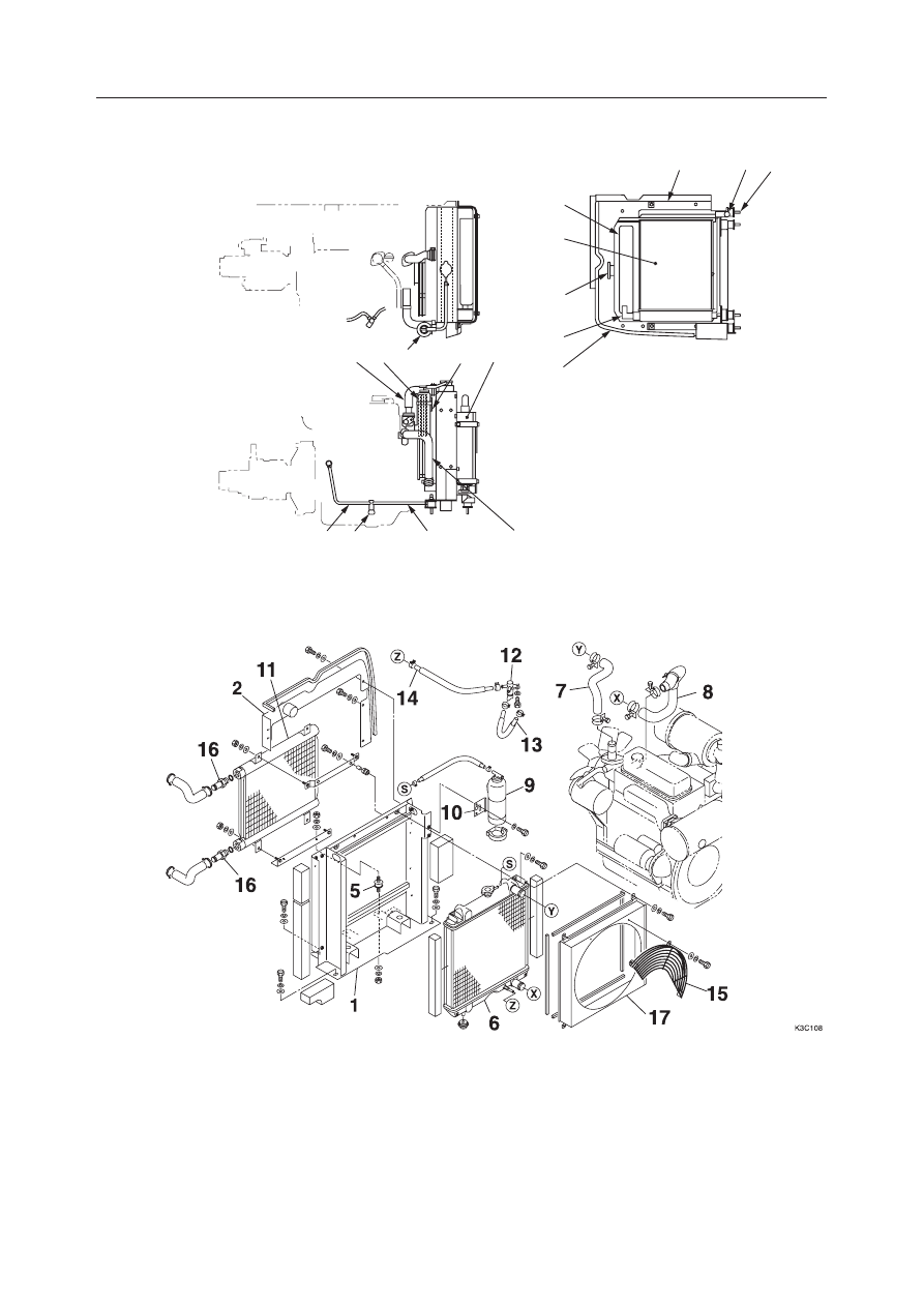
  1. Bracket
  2. Plate
  3. Cover
  4. Net
  5. Cushion Rubber
  6. Radiator

  7. Radiator Hose (Top)
  8. Radiator Hose (Bottom)
  9. Sub Tank
10. Bracket
11. Oil Cooler
12. Drain Valve

13. Tube
14. Tube
15. Fan Guard
16. Hose Nipple
17. Shroud

K3C101

1

16 5

3

4

6

16

2

9

7 15

10

11

14 12

13

8

TB145: S/N 14513261~

III-11

MACHINE CONFIGURATION

DRIVE SYSTEM

TB125, 135, 145

Pump Coupling

TB125: S/N 12510003~12512125, TB145

TB125: S/N 12512126~

  1. Engine Housing
  2. Hydraulic Pump
  3. Coupling

A: Apply molybdenum disulfide grease.
B: Tightening Torque: 102 N·m (10.4 kgf·m)
C: Tightening Torque: 54.9 N·m (5.6 kgf·m)
D: Tightening Torque: 88.3~112.8 N·m (9~11.5 kgf·m)
E: Tightening Torque: 147~176.4 N·m (15~18 kgf·m)

K3C102

2

B

1

A

E

C

3

III-12

MACHINE CONFIGURATION

DRIVE SYSTEM

TB125, 135, 145

TB135

  1. Engine Housing
  2. Hydraulic Pump
  3. Coupling

A: Apply molybdenum disulfide grease.
B:

 102 N·m

C:

 54.9 N·m

D:

 88.3~112.8 N·m (S/N 13510004~13512532)
 102 N·m (S/N 13512533~)

The pump coupling connects the engine flywheel and
the hydraulic pump’s drive shaft. It is constructed so
that it absorbs vibrations, torsions, impact and out of
center of the engine and hydraulic pump.

• Refer to the table concerning the responsibility

of each of the pumps shown in the drawing at
right.

Right Travel, Boom, Bucket

Left Travel, Arm, Swing, Auxiliary

Slew, Dozer Blade

Lever Lock

2nd Speed Travel

Slew P.B. Release

P1

P2

P3

P4

G4C103

P4

P2, P1

P3

III-13

MACHINE CONFIGURATION

DRIVE SYSTEM

TB125, 135, 145

Fuel Tank and Lines

TB125, TB135

  1. Fuel Tank
  2. Cap
  3. Strainer
  4. Drain Cock
  5. Fuel Sender
  6. Water Separator
  7. Feed Pump
  8. Float

A: Tightening Torque: 47 N·m (4.8 kgf·m)

Apply thread lock.

B: Tightening Torque: 47 N·m (4.8 kgf·m)

G4C104

B

A

6

3

2

5

1

7

A

A

4

8

III-14

MACHINE CONFIGURATION

DRIVE SYSTEM

TB125, 135, 145

TB145

  1. Fuel Tank
  2. Cap
  3. Strainer
  4. Drain Cock
  5. Fuel Sender
  6. Water Separator
  7. Feed Pump
  8. Float

A: Tightening Torque: 47 N·m (4.8 kgf·m)

Apply thread lock.

B: Tightening Torque: 47 N·m (4.8 kgf·m)

K3C103

B

A

A

A

6

2

3

1

5

7

4

8

III-15

MACHINE CONFIGURATION

DRIVE SYSTEM

TB125, 135, 145

Engine Control

  1. Lever
  2. Bracket
  3. Accelerator Wire
  4. Washer
  5. Wire Stopper
  6. Wire Stopper
  7. Conical Washer

A: Apply molybdenum disulfide grease.

G4C105

1

3

2

5

7

4

A

6

III-16

MACHINE CONFIGURATION

DRIVE SYSTEM

TB125, 135, 145

Decelerator Unit

  1. Bracket
  2. Bracket
  3. Lever
  4. Pin
  5. Bracket
  6. Motor

A: Apply molybdenum disulfide grease.
B: Apply thread-locking compound.

6

5

A

1

B

2

4

A

3

A

G4C106

III-17

MACHINE CONFIGURATION

DRIVE SYSTEM

TB125, 135, 145

DISASSEMBLY AND ASSEMBLY

Removing the Engine

1. Disconnect the battery ground cable (1) from the

battery.

2. Remove the canopy or cab.

“Removing the Cab”

3. Remove the engine hood, and engine cover.

“Removing the Covers”

4. Remove the radiator and oil cooler.

“Removing the Radiator and Oil Cooler”

5. Disconnect the coolant drain hose (2).

6. Remove the fuel tank.

“Removing the Fuel Tank”

7. Remove the hydraulic pump.

“Removing the Hydraulic Pump”

8. Disconnect the accelerator wire (3) and the decel-

erator wire (4) from the engine, then remove the
bracket (5) together with the wires.

9. Disconnect the battery cable (6) and all the con-

nections on the engine side of the electric wirings
(7).
• Attach identification labels to individual wir-

ings.

• Disconnect the wirings from the clamp and the

band.

10. Disconnect the engine ground cable (8).

11. <TB145 only> Take out the securing bolts and

remove the two stoppers (9).
• Tightening torque:

102 

±

5.1 N·m (10.4 

±

0.52 kgf·m)

• Apply thread lock (Three Bond #1324) to the

bolts.

12. Remove the cushion rubber securing double nuts

(10) on the four positions.
• Tightening torque (upper): 102 N·m (10.4 kgf·m)
• Tightening torque (lower): 81.4 N·m (8.3 kgf·m)

13. <TB145 only> Remove the two stoppers (11).

14. Remove the cushion rubbers.

• Label each cushion rubber to identify for cor-

rect installation.

G4C107

1

G4C109

6

7

8

G4C108

10

2

5

10

3

4

<TB125, TB135>

K3C104

11

10

2

9

10

3

4

5

<TB145>

III-18

MACHINE CONFIGURATION

DRIVE SYSTEM

TB125, 135, 145

15. Suspend the engine temporarily, and remove the

mount and the engine.

Installing the Engine

Follow the same procedure as for removal in the
reverse order.

III-19

MACHINE CONFIGURATION

DRIVE SYSTEM

TB125, 135, 145

PARALLEL

RIGHT ANGLE

G4C110

1

G4C111

7

3

8

4

2

G4C112

6

5

9

Removing the Radiator and Oil Cooler

1. Remove the canopy or cab.

“Removing the Cab”

2. Remove the engine hood, and engine cover.

“Removing the Covers”

3. Loosen the drain cock (1) to drain the engine

coolant.
• Coolant volume:

TB125…4.5 

l, 

TB135…5.4 

l

, TB145…6.7 

l

4. Disconnect the coolant drain hose (2).

5. Disconnect the radiator hoses (3) and (4).

6. Disconnect the oil cooler hoses (5) and (6).

• Prepare a plate to catch drips of the hydraulic

oil.

7. Remove the fan guard (7).

8. Remove the cushion rubber securing nuts (8).

• TB125, TB135…3 nuts, TB145…4 nuts

9. Suspend the radiator and oil cooler (9) together

with the bracket.
• Lift the radiator and oil cooler slowly, sliding

it out forward so the shroud doesn’t hit against
the cooling fan.

Installing the Radiator and Oil Cooler

Follow the same procedure as for removal in the
reverse order.
• The radiator should be mounted at right angles to

the main body frame and parallel to the cooling fan.

III-20

MACHINE CONFIGURATION

DRIVE SYSTEM

TB125, 135, 145

3

6

7

1

4

2

5

G4C113

<TB135>

A

G4C114

Removing the Hydraulic Pump

1. Remove the canopy or cab.

“Removing the Cab”

2. Remove the engine hood and engine cover.

“Removing the Covers”

3. Remove the fuel tank.

“Removing the Fuel Tank”

4. Drain out the oil from the hydraulic tank.

“Removing the Hydraulic Tank”

5. Disconnect the electric wirings from the Solenoid

Valve (1).

6. Disconnect the suction hose (2) from the pump.

7. Disconnect the discharge hoses (3) from the pump.

8. Disconnect the hoses (4) from Solenoid Valve

(1).

9. Remove the fixing bolts (5) and take out the

hydraulic pump (6).
• Tightening torque: 102 

±

5.1 N·m

(10.4 

±

0.52 kgf·m)

• Apply molybdenum disulfide grease to the

spline section (A).

Installing the Hydraulic Pump

Follow the same procedure as for removal in the
reverse order.

Cautions when starting the hydraulic pump

1. Fill the pump housing with clean hydraulic oil

before starting the pump.
• Loosen the air release plug (7), fill in the oil

through the opening until the oil overflows,
and fasten the plug.

2. After starting the engine, let it run at a low idling

speed for a while to completely bleed out the air
within the circuit.

3

K3C105

4

1

5

7

6

<TB125, TB145>

2

III-21

MACHINE CONFIGURATION

DRIVE SYSTEM

TB125, 135, 145

K3C106

6

1

5

4

<TB145>

G4C116

7

2

3

6

Removing the Fuel Tank

1. Remove the canopy or cab.

“Removing the Cab”

2. Remove the covers around the tank.

“Removing the Covers”

3. Loosen the drain cock (1) to drain out the fuel.

• Fuel tank capacity:

TB125

TB135…51 

l, 

TB145…73 

l

4. Remove the Hydraulic Tank.

“Removing the Hydraulic Tank”

5. Disconnect the fuel sender wiring (2) and fuel

pump wiring (3).

6. Disconnect the fuel hoses (4) and (5).

7. Suspend the fuel tank (6) temporarily and remove

the fixing bolts (7).
• Tightening torque:

47.1 

±

2.4 N·m(4.8 

±

0.24 kgf·m)

• Apply thread lock to the bolts.

8. Suspend the fuel tank (6) and remove it.

• Fuel tank mass:

TB125

TB135…26 kg

TB145…32 kg

Installing the Fuel Tank

Follow the same procedure as for removal in the
reverse order.

G4C115

1

4

5

6

< TB125, TB135 >

III-22

MACHINE CONFIGURATION

DRIVE SYSTEM

TB125, 135, 145

III-23

MACHINE CONFIGURATION

SLEW SYSTEM

TB125, 135, 145

  1. Slew Bearing
  2. Swivel Joint
  3. Stopper
  4. Slew Motor
  5. Grease Bath

A: Tightening Torque: 157.9 N·m (16.1 kgf·m)

Apply thread lock.

B: Tightening Torque: 256 N·m (26.1 kgf·m)

Apply thread lock.

C: Tightening Torque: 102 N·m (10.4 kgf·m)
D: Tightening Torque: 102 N·m (10.4 kgf·m)

Apply thread lock.

E: Tightening Torque: 26.5 N·m (2.7 kgf·m)

Apply thread lock.

SLEW SYSTEM

CONSTRUCTION

C

3

2

D

E

4

B

1

E5C200

< TB125 >

A

< TB125, TB135 >

5

< TB145 >

< TB135, TB145 >

III-24

MACHINE CONFIGURATION

SLEW SYSTEM

TB125, 135, 145

Slew Bearing

TB125, TB135

TB145

The slew bearing is a ball type bearing, with balls (3)
and spacers (4) aligned alternately in the groove
between the outer race (1) and inner race (2). The slew
bearing is installed by attaching the outer race to the
turntable and the inner race to the lower frame using
hex bolts.
The slew speed reducer’s pining, mounted on the
turntable, engages with the gear formed on the inside
of the inner race and rotates, slewing the machine’s
frame during operation.

  1. Outer Race
  2. Inner Race
  3. Ball

  4. Spacer
  5. Seal
  6. Seal

The above figure shows the components of the TB 135

3

6

5

2

4

1

K3C201

III-25

MACHINE CONFIGURATION

SLEW SYSTEM

TB125, 135, 145

DISASSEMBLY AND ASSEMBLY

Removing the Slew Motor

1. Remove the cab.

“Removing the Cab”

2. Remove the floor frame.

“Removing the Floor Frame”

3. Disconnect the hydraulic piping (1) from the slew

motor (2).

4. Take out the installation bolts (3), suspend the

slew motor and remove it.
• Tightening torque:

TB125, TB135…157.9 N·m (16.1 kgf·m)
TB145…256 N·m (26.1 kgf·m)
Apply thread lock to the bolts.

• Slew motor mass:

TB125…32 kg, TB135…39 kg, TB145…56 kg

Installing the Slew Motor

Follow the same procedure as for removal in the
reverse order.

Removing the Slew Bearing

1. Remove the hoe attachment

“Attachments, Disassembly and Assembly”

2. Remove the upper frame.

“Removing the Upper Frame”

3. Remove the inner race fixing bolts.

• Tightening torque:

TB125, TB135…102 N·m (10.4 kgf·m)
TB145…256 N·m (26.1 kgf·m)

• Apply thread lock to the bolts.

4. Suspend the slew bearing and remove it.

• Slew bearing mass:

TB125, TB135…40 kg, TB145…84 kg

G4C201

G4C202

2

1

3


Content      ..     5      6      7      8     ..