Takeuchi compact excavator TB125, TB135, TB145 / diesel TNE / diesel Yanmar. Service Manual - page 6
 

  Index      Manuals     Takeuchi compact excavator TB125 (12510003~), TB135 (13510004~), TB145 (14510004~) / diesel TNE / diesel Yanmar. Service Manual


Search            copyright infringement  


Content      ..     4      5      6      7     ..


Takeuchi compact excavator TB125, TB135, TB145 / diesel TNE / diesel Yanmar. Service Manual - page 6


II-60

SPECIFICATIONS

STANDARDS FOR JUDGING PERFORMANCE

TB125, 135, 145

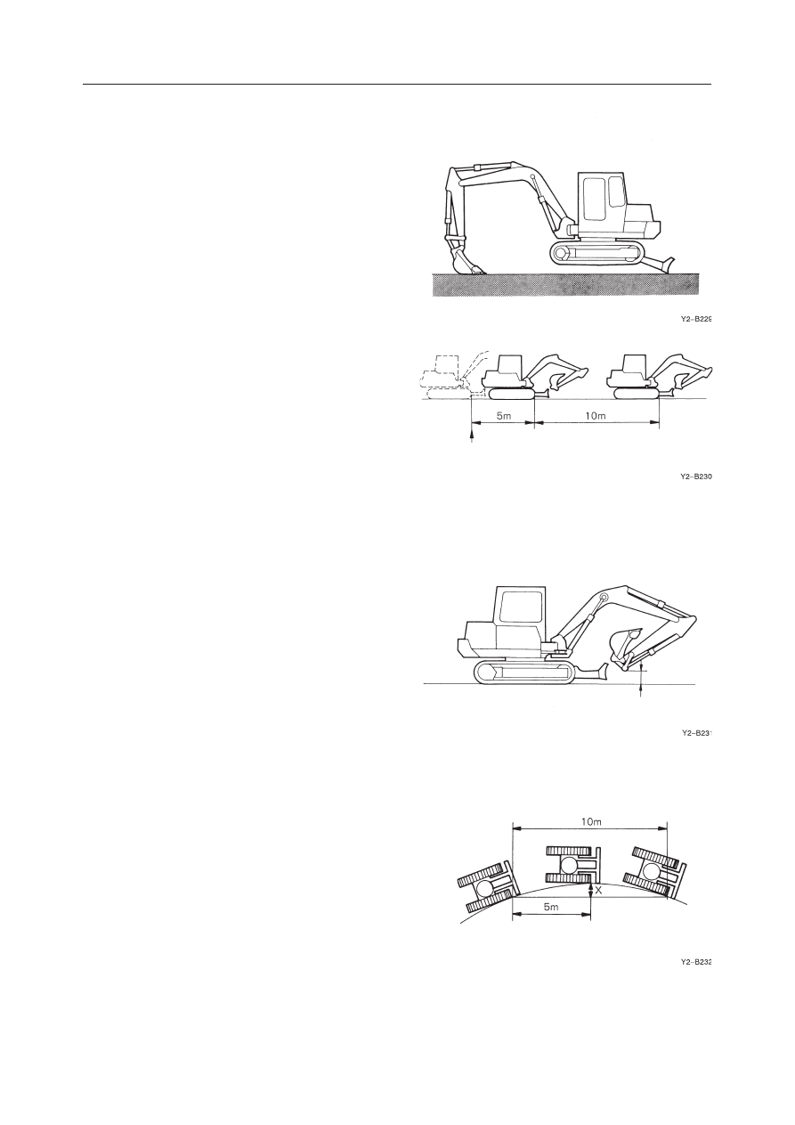
Travel Speed (5 Revolutions)

• Engine

: Rated r.p.m.

• Hydraulic Oil Temp. : 50~60

°

C

• Measurement Posture : Excavator body raised

using both hoe attachment and dozer blade.

• Set crawler belts in motion. Starting after one

full revolution, measure the time required for 5
revolutions. (To measure speed after it has sta-
bilized.)

Travel Speed (10m)

• Engine

: Rated r.p.m.

• Hydraulic Oil Temp. : 50~60

°

C

• Measurement Posture : Travel Posture
• Set excavator in motion. Starting after a distance

of 5 meters, measure the time required to travel
10 meters. Do this on level ground.

Travel Posture

Fully extend the arm and bucket cylinders and
adjust the hoe attachment so that its lowest part
is even with the excavator’s minimum ground
clearance level. The hoe attachment, of course,
should be in a no-load state and the dozer blade
should not be touching the ground.

Travel Curve

• Engine

: Rated r.p.m.

• Hydraulic Oil Temp. : 50~60

°

C

• Measurement Posture : Travel Posture
• Starting after an approach of 5 meters, drive the

excavator in a turn for 10 meters, then measure
the distance of X (5 m point). Do this on level
ground.

START

APPROACH

MEASURED
STRETCH

MIN. GROUND
CLEARANCE

II-61

SPECIFICATIONS

STANDARDS FOR JUDGING PERFORMANCE

TB125, 135, 145

BUCKET PIN

BOOM FOOT PIN

START

LEVER BACK
TO NEUTRAL

OVER RUN

DEVIATION

Natural Travel Drop

• Engine

: Stopped

• Hydraulic Oil Temp. : 50~60

°

C

• Gradient

: 15

°

• Measurement Posture : Fully extend the boom,

arm and bucket cylinders and completely retract
the dozer blade cylinder.

• With the excavator parked at angle for 5 min-

utes, measure the extent of natural drop.

Slew Time

• Engine

: Rated r.p.m.

• Hydraulic Oil Temp. : 50~60

°

C

• Measurement Posture : Completely retract the

arm cylinder, fully extend the bucket cylinder
and adjust so that boom foot pin and bucket pin
are at matching height. Rest the dozer blade on
the ground.

• With the hoe attachment in a no-load state, wait

1 rotation, then measure the time required for
the next 2 rotations.

Overrun When Slewing Stops

• Engine

: Rated r.p.m.

• Hydraulic Oil Temp. : 50~60

°

C

• Measurement Posture : Same as that for mea-

suring slew time.

• Draw matching marks on the outer race of the

slew bearing and lower frame at an exactly 180
degrees rotation from the starting point. With
the hoe attachment in a  no-load state, rotate 180
degrees at, which point return the operation
lever to neutral. Measure the differential be-
tween the position marks and the point the hoe
attachment stops.

Natural Slew Drop

• Engine

: Stopped

• Hydraulic Oil Temp. : 50~60

°

C

• Gradient

: 15

°

• Measurement Posture : Same as that for mea-

suring slew time.

• Rotate the upper machinery so that it is directly

abeam of the grade, then draw positional marks
on the slew bearing’s outer race and the lower
frame. Then measure the distance that develops
between the marks after 5 minutes.

II-62

SPECIFICATIONS

STANDARDS FOR JUDGING PERFORMANCE

TB125, 135, 145

FULLY
RETRACTED

FULLY EXTENDED

Boom Cylinder Speed

• Engine

: Rated r.p.m.

• Hydraulic Oil Temp. : 50~60

°

C

• Measurement Posture : Completely retract the

arm cylinder, fully extend the bucket cylinder
and rest the dozer blade on the ground.

• Then measure the time required for the bucket to

reach its highest elevation point (lowest point)
from its lowest point (highest point) resting on
the ground. (Do not include the cushioning
time.)

Arm Cylinder Speed

• Engine

: Rated r.p.m.

• Hydraulic Oil Temp. : 50~60

°

C

• Measurement Posture : Completely retract the

arm cylinder, fully extend the bucket cylinder,
position the arm horizontally and rest the dozer
blade on the ground.

• Then measure the time required for the arm

cylinder to completely retract (extend) from a
fully extended state (retracted state).

Bucket Cylinder Speed

• Engine

: Rated r.p.m.

• Hydraulic Oil Temp. : 50~60

°

C

• Measurement Posture : Completely retract the

arm cylinder, position the arm horizontally and
rest the dozer blade on the ground.

• Then measure the time required for the bucket

cylinder to completely retract (extend) from a
fully extended state (retracted state).

Dozer Blade Cylinder Speed

• Engine

: Rated r.p.m.

• Hydraulic Oil Temp. : 50~60

°

C

• Measurement Posture : Using the hoe attach-

ment, lift up the dozer blade end of the excava-
tor.

• Then, raising and lowering the dozer blade full

stroke, measure the time required per stroke in
each direction.

II-63

SPECIFICATIONS

STANDARDS FOR JUDGING PERFORMANCE

TB125, 135, 145

Swing Cylinder Speed

• Engine

: Rated r.p.m.

• Hydraulic Oil Temp. : 50~60

°

C

• Measurement Posture : Same as that for mea-

suring slew time.

• While swinging the boom left (right) to right

(left), measure the time required for a full stroke
each way.

(Do not include the cushioning time.)

Natural Cylinder Drop
Boom, Arm, Bucket, Dozer Blade, Bucket Tip

• Engine

: Rated r.p.m.

• Hydraulic Oil Temp. : 50~60

°

C

• Measurement Posture : Completely retract the

dozer blade and arm cylinders, fully extend the
bucket cylinder and adjust the bucket pin posi-
tion to the same height as the boom foot pin.

• Maintain this position for 10 minutes, then mea-

sure the change in rod length and the distance the
bucket tip falls.

Swing Cylinder

• Engine

: Stopped

• Hydraulic Oil Temp. : 50~60

˚

C

• Gradient

: 15

˚

• Measurement Posture : Same as that for mea-

suring slew time.

• Rotate the upper machinery so that it is directly

abeam of the grade, then measure the change in
rod length after 5 minutes.

II-64

SPECIFICATIONS

STANDARDS FOR JUDGING PERFORMANCE

TB125, 135, 145

Lever Operating Force

• With the engine stopped, attach a push-pull

scale to the center of the operation lever’s handle
grip, or in the case of a pedal, position a push-
pull scale to its tip and record the measurement
at the point the lever/pedal reaches full stroke.

Lever Play

• Measure any discernible play at the tip of the

lever (pedal).

Backlash

• Measurement Posture : Completely retract the

arm cylinder and fully extend the bucket cylin-
der.

• Move the tips of the bucket teeth from side to

side (left and right) and measure the play.

Slew Bearing Play

1. Attach a dial gauge to the bot-

tom face of the slew bearing’s
race located near the front of
the upper machinery.

2. Raise the crawler on one side

off the ground and set the dial
gauge to zero.

3. Then raise the opposite

crawler and read the dial
gauge.

II-65

SPECIFICATIONS

STANDARDS FOR JUDGING PERFORMANCE

TB125, 135, 145

Crawler Tension

• Raise the excavator completely off the ground

using the hoe attachment and dozer blade.

Then measure the distance (of droop) between

the center point on the crawler frame and top of
the crawler shoe.
Note: For the rubber crawler, the measuring

should be performed after placing the
joint portion with “M” mark to the top
center.

II-66

SPECIFICATIONS

STANDARDS FOR JUDGING PERFORMANCE

TB125, 135, 145

III-1

TB125, 135, 145

III .

  MACHINE  CONFIGURATION

III-2

MACHINE CONFIGURATION

TB125, 135, 145

CONTENTS

Drive System ......................................................................................................................................................... 3

Slew System ........................................................................................................................................................ 23

Travel System ...................................................................................................................................................... 27

Upper Frame ........................................................................................................................................................ 41

Control System .................................................................................................................................................... 53

Attachments ......................................................................................................................................................... 65

Hydraulic System ................................................................................................................................................ 71

Electrical System ................................................................................................................................................. 91

Proportional Control .......................................................................................................................................... 115

Air Conditioner System ..................................................................................................................................... 119

Security System ................................................................................................................................................. 189

III-3

MACHINE CONFIGURATION

DRIVE SYSTEM

TB125, 135, 145

DRIVE SYSTEM

CONSTRUCTION

Engine Mount

TB125: S/N 12510003~12514525, TB135: S/N 13510004~13514050

  1. Engine Foot FR
  2. Engine Foot FL
  3. Engine Foot RR
  4. Engine Foot RL
  5. Air Hose
  6. Air Hose
  7. Cushion Rubber

  8. Cushion Rubber
  9. Resonator
10. Exhaust Pipe (for Cab)
11. Exhaust Pipe (for Canopy)
12. Ground Cable
13. Silencer

A: Tightening Torque: 102 N·m (10.4 kgf·m)
B: Tightening Torque: 81.4 N·m (8.3 kgf·m)
C: Tightening Torque: 54.9 N·m (5.6 kgf·m)

Apply thread lock.

D: Tightening Torque: 40.9 

±

0.9 N·m (5.0 

±

0.5 kgf·m)

E: Tightening Torque: 25.5 

±

2.9 N·m (2.6 

±

0.3 kgf·m)

G4C100

A

B

7

8

10

11

C

E

D

13

12

6

9

5

3

1

A

B

2

4

REAR SIDE

FRONT SIDE

< TB125 >

10

III-4

MACHINE CONFIGURATION

DRIVE SYSTEM

TB125, 135, 145

TB125: S/N 12514526~

  1. Engine Foot FR
  2. Engine Foot FL
  3. Engine Foot RR
  4. Engine Foot RL
  5. Air Hose
  6. Air Hose
  7. Cushion Rubber

  8. Cushion Rubber
  9. Resonator
10. Exhaust Pipe (for Cab)
11. Exhaust Pipe (for Canopy)
12. Ground Cable
13. Silencer

A:

: 102 N·m

B:

: 81.4 N·m

C:

: 54.9 N·m; Apply thread-locking compound.

D:

: 97.1 N·m; Apply thread-locking compound.

E: Apply thread-locking compound.

III-5

MACHINE CONFIGURATION

DRIVE SYSTEM

TB125, 135, 145

TB135: S/N 13514051~

  1. Engine Foot FR
  2. Engine Foot FL
  3. Engine Foot RR
  4. Engine Foot RL
  5. Air Hose
  6. Air Hose
  7. Cushion Rubber

  8. Cushion Rubber
  9. Resonator
10. Exhaust Pipe (for Cab)
11. Exhaust Pipe (for Canopy)
12. Ground Cable
13. Silencer

A:

: 102 N·m

B:

: 81.4 N·m

C:

: 54.9 N·m; Apply thread-locking compound.

D: Apply thread-locking compound.

III-6

MACHINE CONFIGURATION

DRIVE SYSTEM

TB125, 135, 145

TB145: S/N 14510004~14513260

  1. Engine Foot FR
  2. Engine Foot FL
  3. Engine Foot RR
  4. Engine Foot RL
  5. Ground Cable
  6. Cushion Rubber
  7. Cushion Rubber
  8. Exhaust Pipe
  9. Air Hose

10. Stopper
11. Stopper
12. Stopper
13. Stopper
14. Resonator
15. Air Hose
16. Air Hose
17. Silencer

A: Tightening Torque: 102 N·m (10.4 kgf·m)
B: Tightening Torque: 81.4 N·m (8.3 kgf·m)
C: Tightening Torque: 102 N·m (10.4 kgf·m)

Apply thread lock.

D: Tightening Torque: 40.9 

±

0.9 N·m (5.0 

±

0.5 kgf·m)

E: Tightening Torque: 25.5 

±

2.9 N·m (2.6 

±

0.3 kgf·m)

C

K3C100

17

8

3

1

15

14

2

9

4

5

A

B

12

13

7

A

B

10

6

11

D

REAR SIDE

FRONT SIDE

E

Canopy Type

16

III-7

MACHINE CONFIGURATION

DRIVE SYSTEM

TB125, 135, 145

TB145: S/N 14513261~

  1. Engine Foot FR
  2. Engine Foot FL
  3. Engine Foot RR
  4. Engine Foot RL
  5. Ground Cable
  6. Cushion Rubber
  7. Cushion Rubber
  8. Exhaust Pipe

  9. Air Hose
10. Stopper
11. Stopper
12. Stopper
13. Stopper
14. Air Hose
15. Silencer

A:

 102 N·m

B:

 81.4 N·m

C:

 54.9 N·m; Apply thread-locking compound.

D: 

 102 N·m; Apply thread-locking compound.

E: Apply thread-locking compound.

III-8

MACHINE CONFIGURATION

DRIVE SYSTEM

TB125, 135, 145

Radiator and Oil Cooler

TB125: S/N 12510003~12514525

  1. Bracket
  2. Plate
  3. Cover
  4. Net
  5. Cushion Rubber
  6. Radiator

  7. Radiator Hose (Top)
  8. Radiator Hose (Bottom)
  9. Sub Tank
10. Bracket
11. Oil Cooler
12. Drain Valve

13. Tube
14. Tube
15. Fan Guard
16. Cushion Rubber
17. Shroud

TB125: S/N 12514526~

E5C100

3

4

5

6

7

8

9

10

11

12

13

14

15

2

1

III-9

MACHINE CONFIGURATION

DRIVE SYSTEM

TB125, 135, 145

TB135: S/N 13510004~13514050

  1. Bracket
  2. Plate
  3. Cover
  4. Net
  5. Cushion Rubber
  6. Radiator

  7. Radiator Hose (Top)
  8. Radiator Hose (Bottom)
  9. Sub Tank
10. Bracket
11. Oil Cooler
12. Drain Valve

13. Tube
14. Tube
15. Fan Guard
16. Shroud

TB135: S/N 13514051~

G4C101

1

2

11

5

6

12

13

8

7

15

9

4

3

10

14


Content      ..     4      5      6      7     ..