Takeuchi compact excavator TB125, TB135, TB145 / diesel TNE / diesel Yanmar. Service Manual - page 8
 

  Index      Manuals     Takeuchi compact excavator TB125 (12510003~), TB135 (13510004~), TB145 (14510004~) / diesel TNE / diesel Yanmar. Service Manual


Search            copyright infringement  


Content      ..     6      7      8      9     ..


Takeuchi compact excavator TB125, TB135, TB145 / diesel TNE / diesel Yanmar. Service Manual - page 8


III-26

MACHINE CONFIGURATION

SLEW SYSTEM

TB125, 135, 145

FRONT

REAMER BOLT

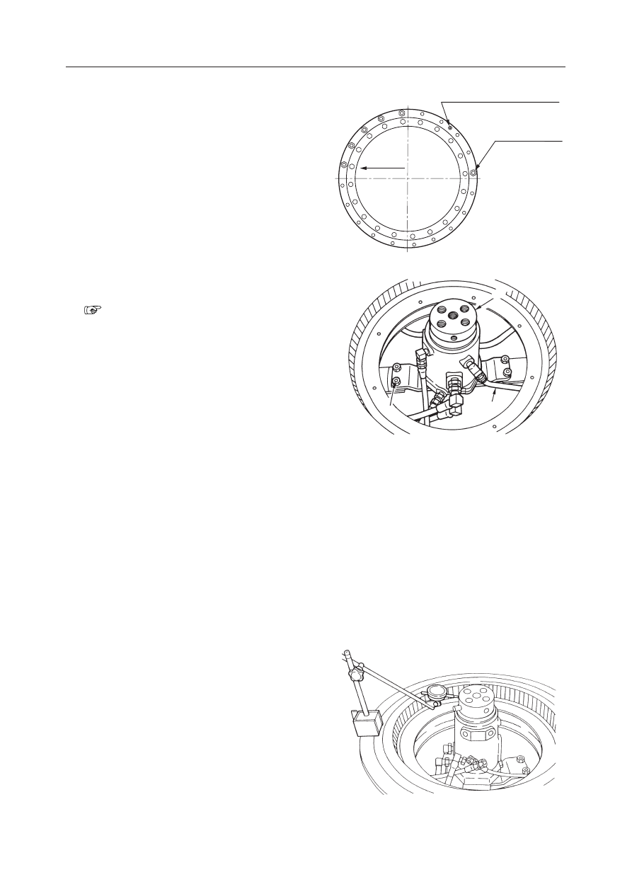
GREASE APPLYING HOLE

G4C203

3

2

1

G4C204

G4C205

Installing the Slew Bearing

Follow the same procedure as for removal in the
reverse order.
• When mounting the slew bearing on the upper

frame, be sure to position the reamer bolts and the
grease holes as illustrated in the right figure.

• Apply grease to the inner teeth of the slew bearing.

Removing the Swivel Joint

1. Remove the upper frame.

“Removing the Upper Frame”

2. Disconnect the hydraulic hoses (1) from the hub

side of the swivel joint.
• Make match marks at the connection positions

of the hoses.

3. Remove the swivel joint fixing bolts (2).

• Tightening torque:

TB125…26.5 N·m (2.7 kgf·m)
TB135, TB145…102 N·m (10.4 kgf·m)

• Apply thread lock to the bolts.

4. Suspend the swivel joint (3) and remove it.

• Swivel joint mass:

TB125…11 kg
TB135, TB145…22 kg

Installing the Swivel Joint

Follow the same procedure as for removal in the
reverse order.
• When mounting the swivel joint, tighten it tempo-

rarily with the fixing bolts, and center the swivel
joint by using a dial gauge.

• Adjust the centering so that the deviation from the

center is within 0.25 mm.

III-27

MACHINE CONFIGURATION

TRAVEL SYSTEM

TB125, 135, 145

TRAVEL SYSTEM

CONSTRUCTION

  1. Lower Frame
  2. Crawler Belt
  3. Carrier Roller
  4. Track Roller

  5. Idler
  6. Track Adjuster
  7. Travel Motor
  8. Sprocket

The above figure shows the components of the TB135.

G4C300

8

1

3

7

6

4

2

5

III-28

MACHINE CONFIGURATION

TRAVEL SYSTEM

TB125, 135, 145

Rubber Crawler Belt

TB125, TB135

TB145

  1. Cover Rubber
  2. Steel Cord
  3. Core

  1. Cover Rubber
  2. Steel Cord
  3. Core

2

1

E5C300

3

K3C310

2

3

1

III-29

MACHINE CONFIGURATION

TRAVEL SYSTEM

TB125, 135, 145

Steel Crawler Belt

TB125, TB135

TB145

  1. Link R
  2. Link L
  3. Master Link R
  4. Master Link L
  5. Bushing
  6. Track Pin
  7. Master Pin
  8. Spiro-lox
  9. Shoe Plate

  1. Link R
  2. Link L
  3. Master Link R
  4. Master Link L
  5. Bushing
  6. Track Pin
  7. Master Pin
  8. Cotter Pin
  9. Bolt
10. Nut
11. Shoe Plate

9

4

3

7

8

2

1

6

5

G4C302

2

1

7

8

3

4

6

5

11

10

9

K3C301

III-30

MACHINE CONFIGURATION

TRAVEL SYSTEM

TB125, 135, 145

Carrier Roller

TB125, TB135

TB145

  1. Roller
  2. Shaft
  3. Bearing
  4. Cover
  5. Cover
  6. Oil Filler Plug

  1. Roller
  2. Shaft
  3. Bearing
  4. Cover
  5. Cover
  6. Oil Filler Plug

A: Tightening Torque: 65.7 N·m

Apply thread lock.

Lube oil capacity: 45 mL

A: Tightening Torque: 256 N·m

Apply thread lock.

Lube oil capacity: 60 mL

6

5

3

1

4

2

G4C303

A

6

5

2

3

1

4

A

K3C302

III-31

MACHINE CONFIGURATION

TRAVEL SYSTEM

TB125, 135, 145

Track Roller

TB125, TB135

TB145

  1. Roller
  2. Cover
  3. Shaft
  4. Bushing
  5. Floating Seal
  6. Oil Filler Plug
  7. Spacer

(for steel crawler)

A: Tightening Torque: 157.9 N·m
Lube oil capacity: 70 mL

A: Tightening Torque: 102 

±

5.1 N·m

Lube oil capacity: 65 mL

  1. Roller
  2. Shaft
  3. Cover
  4. Retainer
  5. Bearing
  6. Floating Seal
  7. Oil Filler Plug
  8. Stopper

(for steel crawler)

2

4

7

1

5

6

3

8

G4C304

A

K3C303

2

3

A

1

6

4

5

7

III-32

MACHINE CONFIGURATION

TRAVEL SYSTEM

TB125, 135, 145

Idler

TB125, TB135

TB145

  1. Idler
  2. Slide
  3. Shaft
  4. Bushing
  5. Floating Seal
  6. Oil Filler Plug

  1. Idler
  2. Slide
  3. Shaft
  4. Bushing
  5. Floating Seal
  6. Oil Filler Plug

6

1

2

3

4

5

G4C305

3

6

1

4

5

2

K3C304

Lube oil capacity: 50 mL

Lube oil capacity: 70 mL

III-33

MACHINE CONFIGURATION

TRAVEL SYSTEM

TB125, 135, 145

Track Adjuster

TB125, TB135, TB145 (Standard)

TB145 (Automatic)

  1. Cylinder
  2. Piston
  3. Plate

  4. Reach Rod
  5. Spring
  6. Check Valve Assembly

  7. Oil Seal
  8. O-ring
  9. Backup Ring

  1. Cylinder
  2. Reach Rod
  3. Plate
  4. Spring
  5. Handle
  6. Lock Plate

G4C306

6

1

8

9

7

2

4

5

3

III-34

MACHINE CONFIGURATION

TRAVEL SYSTEM

TB125, 135, 145

DISASSEMBLY AND ASSEMBLY

Removing the Rubber Crawler

TB125, TB135, TB145 (Standard)

1. Loosen the tension of the crawler (1).

When loosening the check valve (2), turn it slowly.
Do not loosen it beyond the point where grease
starts to ooze out. If it is difficult for the grease to
come out, move the machine forward and in
reverse.
• Check valve tightening torque:

177 N·m (18 kgf·m)

2. Raise the body and after engaging pieces of iron

pipe (3) in the crawler, rotate the sprocket in the
reverse direction.

3. When the iron pipes reach a point just to the side

of the idler (4), stop rotating the sprocket.

4. Slide the crawler to the side to remove it.

• Rubber crawler mass: TB125…124 kg

TB135…149 kg, TB145…219 kg

Installing the Rubber Crawler

TB125, TB135, TB145 (Standard)

1. Raise the machine body and set the crawler (1) on

the frame.
• The Crawler should engage in the sprocket.

2. Engage pieces of iron pipe (3) in the crawler, then

rotate the sprocket in the reverse direction.

3. When the iron pipes reach a point just to the side

of the idler, stop rotating the sprocket.

4. Slide the crawler to a position where it will fit

snugly with the idler.

5. Engage the crawler fully with the sprocket and the

idler, then adjust the crawler tension.

“II. Specifications, Standards for Judging
Performance”

1

4

2

C4C308

III-35

MACHINE CONFIGURATION

TRAVEL SYSTEM

TB125, 135, 145

K3C306

K3C308

K3C306

Removing the Rubber Crawler

TB145 (Automatic)

When the travel speed switch is set to the 2nd speed
side while the engine is running, the tensioning cylin-
der rods extend and the crawlers are tightened.
Always keep the switch at the 1st speed side except
when tightening the crawlers.
1. Start the engine and raise the machine body

500mm with the hoe attachment and dozer blade.

2. Stop the engine.
3. Remove the valve covers.
4. Turn the lock plate (1) counterclockwise to disen-

gage the handle lock.

5. Turn the valve handle (2) counterclockwise to

loosen the tension of the crawler. Do the same for
the other side.

6. Close both the tensioning cylinder valves before

removing the crawlers.

7. Slowly lower the dozer blade side of the machine

body, by the dozer blade lever. (Do not start the
engine.)

8. Ground the crawlers and lower the machine body

so that the crawler slack is maximum.

9. When the crawlers come away from the idlers,

slide the crawlers to the outside and remove them.

10. Disengage the crawlers and sprockets, then re-

move the crawlers from the crawler frames.

Installing the Rubber Crawler

TB145 (Automatic)

1. Engage the crawlers with the left and right sprock-

ets.

2. Set the left and right crawlers on the idlers.
3. Start the engine.
4. Press the travel speed switch once and set it to the

2nd speed side. The left and right crawlers are
tightened simultaneously.

5. Check that the crawlers are properly tightened.

 “II. Specifications, Standards for judging

performance” concerning adjustment dimen-
sions and methods.

III-36

MACHINE CONFIGURATION

TRAVEL SYSTEM

TB125, 135, 145

3

1

2

C4C309

Removing the Steel Crawler

TB125, TB135, TB145 (Standard)

1. Stop the machine so that master pin is front of the

idler.

2. Loosen the tension of the crawler (1).

When loosening the check valve (2), turn it slowly.
Do not loosen it beyond the point where grease
starts to ooze out. If it is difficult for the grease to
come out, move the machine forward and in
reverse.
• Check valve tightening torque:

177 N·m (18 kgf·m)

3. Take out the master pin (3) and separate the ends

of the crawler (1).

4. Raise the body, then open up the crawler (1) while

running the travel motor slowly in reverse.
• Use the dozer blade and hoe attachment to

raise the body, It should be kept level as it is
raised.

• Steel Crawler mass: TB125…153 kg

TB135…199 kg, TB145…259 kg

Installing the Steel Crawler

TB125, TB135, TB145 (Standard)

1. Raise the body and position the crawler beneath

the frame.
• Be careful not to mistake the installation direc-

tion of the crawler.

2. Engage the links in the sprocket, then run the

travel motor slowly in the forward direction to
wrap the crawler around the frame.

3. After lowering the body, install the master pin to

join the ends of the crawle.
• After aligning the pin holes, insert a temporary

pin before inserting the master pin.

4. Raise the body and adjust the crawler tension.

“II, Specifications, Standards for judging
performance”

III-37

MACHINE CONFIGURATION

TRAVEL SYSTEM

TB125, 135, 145

Removing the Steel Crawler

TB145 (Automatic)

• Stop the machine so that the master pin is

positioned at the front of the idler.

1. Raise the body.

2. Release the crawler tension.

“Removing the Rubber Crawler”

3. Pull out the master pin and detach the crawler.

4. Slowly run the travel motor in reverse and gradu-

ally remove the crawler.
• Steel crawler mass: 259 kg

Installing the Steel Crawler

TB145 (Automatic)

1. Raise the body and position the crawler under the

frame.
• Be careful to install the crawler belts in the

proper direction.

2. Engage the links in the sprockets, then slowly run

the travel motor in forward and wrap on the
crawler.

3. Lower the body, then install the master pin and

engage the crawler.
• After lining up the pin hole, first insert the

temporary pin.

4. Tension the crawler.

• Turn on the travel speed switch and tension the

crawler.

 “II. Specifications, Standards for judging

performance” concerning adjustment dimen-
sions and methods.

III-38

MACHINE CONFIGURATION

TRAVEL SYSTEM

TB125, 135, 145

3

4

G4C307

1

2

K3C309

<TB145>

Removing the Carrier Roller

1. Loosen the tension in the crawler belt.

2. Using a hydraulic jack, push up the crawler belt.

3. Loosen the installation nut (3) and remove the

bolt, then remove the upper roller (4).

Installing the Carrier Roller

Follow the procedure used for removal in reverse
order.

• When tightening the installation nut, apply

thread lock to the threads.

• Installation nut tightening torque:

TB125, TB135…65.7 N·m (6.7 kgf·m)
TB145…256 N·m (26.1 kgf·m)

Removing the Track Roller

1. Loosen the crawler tension.

2. Loosen the roller installation bolt (1) slightly

(approximately 1 turn).

3. Raise the machine body, take out the installation

bolt (1) and remove the roller (2).

Installing the Track Roller

1. Tighten the roller (2) installation bolt (1) tempo-

rarily.

2. Bring the machine body in full contact with the

ground, then tighten the bolt.
• Tightening torque:

TB125, TB135…157.9 N·m (16.1 kgf·m)
TB145…102 

±

5.1 N·m (10.4 

±

0.52 kgf·m)

• Apply thread lock to the threads of the instal-

lation bolt.

3. Raise the machine body, then adjust the tension of

the crawler.
Raise the machine body, then adjust the tension of
the crawler.

2

1

G4C308

< TB125, TB135 >

III-39

MACHINE CONFIGURATION

TRAVEL SYSTEM

TB125, 135, 145

Removing the Idler and Track Adjuster

1. Remove the Crawler.

“Removing the Crawler”

2. <TB145 (Automatic) only> Remove the cover,

then disconnect the hydraulic hoses from the
tensioning cylinder.

3. Take out the idler and track adjuster.

• Mass of idler + Track adjuster:
• TB125, TB135…38 kg, TB145…52 kg

Installing the Idler and Track Adjuster

Follow the procedure used for removal in reverse
order.
• Apply grease to the rubbing surfaces of the track

adjuster piston and cylinder.

Removing the Travel Motor

1. Remove the crawler.

“Removing the Crawler”

2. Remove the installation bolts (1) and remove the

sprocket (2).
• Tightening torque:

TB125, TB135…97.1 

±

4.8 N·m (9.9 

±

0.49 kgf·m)

TB145…155.9 

±

7.7 N·m (15.9 

±

0.79 kgf·m)

• Apply thread lock to the bolts.

3. Remove the motor cover and disconnect the hy-

draulic piping (4).

4. Suspend the travel motor (3) temporarily and

remove the fixing bolts (5).
• Tightening torque:

TB125, TB135…97.1 

±

4.8 N·m (9.9 

±

0.49 kgf·m)

TB145…155.9 

±

7.7 N·m (15.9 

±

0.79 kgf·m)

• Apply thread lock to the bolts.

5. Suspend the travel motor (3) and remove it.

• Travel motor mass: TB125…36 kg,

TB135…49 kg, TB145…57 kg

Installing the Travel Motor

Follow the procedure used for removal in reverse
order.

G4C309

4

4

5

III-40

MACHINE CONFIGURATION

TRAVEL SYSTEM

TB125, 135, 145

WARNING

If you must work beneath the raised machine or
equipment, always use wood blocks, jack-stands
or other rigid and stable supports. Never get
under the machine or working equipment if they
are not sufficiently supported.

STOPPER

BOLT

SPACER

BOLT

03713-00100

11010-51450

03913-00400

11010-51255

Item Part Number

Description

Quantity

TB125 TB135 TB145

1

2

3

4

12

12

16

16

20

40

Item Part Number

Description

Quantity

TB125 TB135 TB145

4

12

12

5

6

7

04610-00700

11010-41230

11400-20012

GUIDE

BOLT

WASHER

Refer to the previous pages for removing and install-
ing the crawler belts.

TB125, TB135

1. Remove the track roller.

“Removing the Track Roller”

2. Change the track roller fitting position to the

lower hole (B).
• A (upper hole): fitting hole for rubber crawler
• B (lower hole): fitting hole for steel crawler.

3. Fit the track roller with the stopper (1) added.

• Insert the boss of the stopper into the upper

hole (A).

“Installing the Track Roller”

TB145

1. Remove the track roller.

“Removing the Track Roller”

2. Fit the track roller with the spacer (3) added

between the frame and the roller bracket.

“Installing the Track Roller”

3. Attach the guide (5) to the bottom of the frame on

the idler side, and fix them with a washer (7) and
a bolt (6).

Replacing the Rubber Crawlers with the Steel
Crawlers

Supplementary Parts

III-41

MACHINE CONFIGURATION

UPPER FRAME

TB125, 135, 145

UPPER FRAME

CONSTRUCTION

Turntable

  1. Turntable
  2. Counterweight
  3. Bushing
  4. Rubber (TB135 only)

A: Tightening Torque:

TB125…157.8 N·m (16.1 kgf·m)
TB135, TB145…256 N·m (26.1 kgf·m)

B: Apply thread lock.


Content      ..     6      7      8      9     ..