Takeuchi compact excavator TB125, TB135, TB145 / diesel TNE / diesel Yanmar. Service Manual - page 11
 

  Index      Manuals     Takeuchi compact excavator TB125 (12510003~), TB135 (13510004~), TB145 (14510004~) / diesel TNE / diesel Yanmar. Service Manual


Search            copyright infringement  


Content      ..     9      10      11      12     ..


Takeuchi compact excavator TB125, TB135, TB145 / diesel TNE / diesel Yanmar. Service Manual - page 11


III-88

MACHINE CONFIGURATION

HYDRAULIC SYSTEM

TB125, 135, 145

DISASSEMBLY AND ASSEMBLY

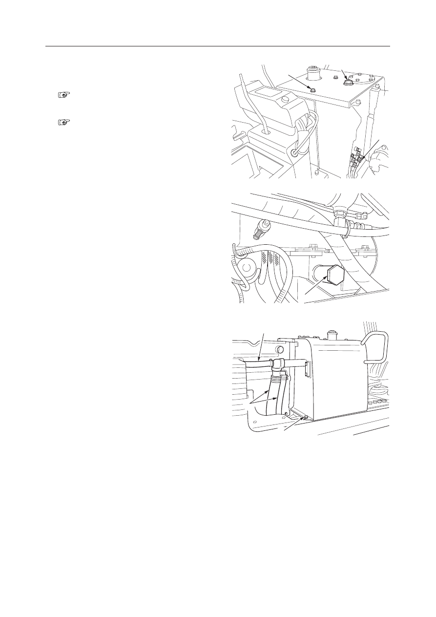
Removing the Hydraulic Tank

1. Remove the cab or canopy.

“Removing the Cab”

2. Remove the covers around the tank.

“Removing the Covers”

3. Drain the oil from the tank.

a. Slowly loosen the plug (1) to release the tank’s

inner pressure.

b. Loosen the drain plug (2) and drain out the oil.

• Tank level capacity:

TB125, TB135…48 

l

, TB145…74 

l

4. Remove the three bolts (3) securing the fuel tank

to the hydraulic tank.

5. Disconnect the low pressure hoses (4) from the

tank.
• TB125, TB135…3 hoses,  TB145…4 hoses

6. Disconnect the hydraulic hoses (5) from the tank.

• TB125, TB135…4 hoses,  TB145…5 hoses
• Attach identification labels to individual hoses

for correct reassembling.

7. Take off the fixing bolts (6), and suspend the tank

and remove it.
• Tank mass:

TB125, TB135…57 kg, TB145…74 kg

Installing the Hydraulic Tank

Follow the same procedure as for removal in the
reverse order.

• Tank fixing bolt tightening torque: 47 N·m

(4.8  kgf·m) [Apply thread lock to the bolt.]

G4C702

5

1

3

G4C703

2

G4C704

4

4

6

III-89

MACHINE CONFIGURATION

HYDRAULIC SYSTEM

TB125, 135, 145

Filling with Hydraulic Oil

1. Fill the tank with the specified amount of hydrau-

lic oil through the filler inlet.

2. Bleed the air from the hydraulic pump.

“Bleeding the air”

3. Run the engine for 2~3minutes at low speed.

4. Retract the arm and bucket cylinders fully, lower

the boom and lower the bucket to the ground.

5. Lower the dozer blade to the ground.

6. Check if the oil level is proper using a level gauge.

“I-12”

Tank Pressurization

1. Extend all the cylinders fully, then in that condi-

tion, close the filler inlet. (The dozer blade should
be lowered to the ground.)
• When filling of the hydraulic tank is com-

pleted, be sure to pressurize the tank.

Bleeding the Air

Bleed the air after replacing the hydraulic oil or
reassembling hydraulic devices or hoses.
1. Remove the vent plug (1), on the hydraulic pump

bleed the air from the housing, and tighten plug
(1) once hydraulic oil begins to come out.
• Be sure to stop the engine.

2. Start the engine and run the engine at low idle.

3. Slowly operate the cylinders until the air is bled.

4. Bleed the air from the cylinders.

a. With the engine running at slow, extend and

contract the cylinders 4 or 5 times.
• Move the piston rods to 100 mm before the

stroke end. DO NOT extend them com-
pletely.

b. Repeat step “a” above with the engine running

at full, then run it at slow and extend the piston
rods completely to the stroke end.

III-90

MACHINE CONFIGURATION

HYDRAULIC SYSTEM

TB125, 135, 145

G4C706

2

1

5

3

4

Changing to Biodegradable Oil

When changing the hydraulic oil from mineral oil to
biodegradable oil, be sure to flush it properly as
described below to prevent mixing of oil, which will
adversely affect the biodegradability and safety. When
changing the hydraulic oil from biodegradable oil to
mineral oil, flushing is not necessary.

Flushing

1. Drain the hydraulic tank.

“Removing the Hydraulic Tank”

2. Disconnect the hoses from the cylinders and drain

the disconnected hoses and cylinders.

3. Supply new biodegradable oil to the hydraulic

tank.

“Filling with Hydraulic Oil”

4. Bleed the air from the pump and cylinders and

pressurize the hydraulic tank.

“Bleeding the Air”

5

Operate the hydraulic actuators for 30 minutes.

6. Drain the tank and cylinders.

7. Replace return filter (2) with a new one.

a. Remove cover (1).
b. Remove filter (2) and replace with a new one.

8. Repeat steps 3 and 4.

9. Operate the hydraulic actuators for 30 minutes.

10. Drain the tank and cylinders.

11. Repeat steps 3 and 4.

12. Operate the hydraulic actuators for 1 hour.

13. Drain the tank and cylinders.

14. Replace the return filter (2) with a new one.

15. Clean suction strainer (5).

a. Loosen the hose clips and disconnect hose (3).
b. Remove flange (4) together with strainer (5).
c. Clean strainer (5).

16. Repeat steps 3 and 4.

17. Operate the hydraulic actuators, then check for oil

leakage.

III-99

MACHINE CONFIGURATION

ELECTRICAL SYSTEM

TB125, 135, 145

Control Box R

  1. Cover
  2. Cover
  3. Cluster Gauge
  4. Bulb
  5. Starter Switch
  6. Lamp Switch
  7. Cover

III-100

MACHINE CONFIGURATION

ELECTRICAL SYSTEM

TB125, 135, 145

Control Box L

  1. Cover
  2. Cover
  3. Wiper Switch
  4. Heater Switch
  5. Cap

2

1

5

3

4

C4C805

CAB

III-101

MACHINE CONFIGURATION

ELECTRICAL SYSTEM

TB125, 135, 145

Electrical Wiring (1/2)

 TB125

  1. Control Unit
  2. Wire Harness
  3. Diode
  4. Diode
  5. Fuse Box
  6. Fusible link

  7. Wire Harness
  8. Wire Harness
  9. Wire Harness
10. Wire Harness
11. Connector
12. Horn

E5C803

III-102

MACHINE CONFIGURATION

ELECTRICAL SYSTEM

TB125, 135, 145

 TB135,TB145

  1. Control Unit
  2. Wire Harness
  3. Diode
  4. Diode
  5. Fuse Box
  6. Fusible link

  7. Wire Harness
  8. Wire Harness
  9. Wire Harness
10. Wire Harness
11. Connector
12. Horn

III-103

MACHINE CONFIGURATION

ELECTRICAL SYSTEM

TB125, 135, 145

Electrical Wiring (2/2)

 TB125

  1. Plate
  2. Relay
  3. Relay
  4. Resistor
  5. Timer Unit

  6. Resistor
  7. Buzzer
  8. Diode
  9. Controller
10. Relay

E5C804

X

X

6

3

2

5

2

10

7

2

4

9

2

2

1

8

4

III-104

MACHINE CONFIGURATION

ELECTRICAL SYSTEM

TB125, 135, 145

 TB135, TB145

  1. Plate
  2. Relay
  3. Relay
  4. Resistor
  5. Timer Unit

  6. Resistor
  7. Buzzer
  8. Diode
  9. Controller
10. Relay

III-105

MACHINE CONFIGURATION

ELECTRICAL SYSTEM

TB125, 135, 145

Travel Alarm

  1. Lever Bracket
  2. Bracket
  3. Plate
  4. Right Travel Lever
  5. Left Travel Lever
  6. Wire Harness
  7. Relay Assembly
  8. Buzzer
  9. Proximity Switch

A: Adjust the travel alarm so that it will sound when the

lever grip is moved forward or backward by about 40
mm.

B: Adjust the lever so that the center of the proximity

switch aligns with the center of the bolt when the lever
is in the neutral position.

C: Do not allow the proximity switch to touch the adjust-

ment bolt.

D: Connect to the power source (+) and the main har-

ness.

E: Connect to the maintenance light socket.
F: Connect to the relay.
G: Connect to the main harness.
H: Connect to the buzzer earth.
 I : Connect to the buzzer.

III-106

MACHINE CONFIGURATION

ELECTRICAL SYSTEM

TB125, 135, 145

Battery

 TB125

  1. Battery
  2. Angle
  3. Cable
  4. Cable
  5. Terminal

  6. Cover
  7. Cap
  8. Bolt
  9. Tube
10. Tube

A: Nut Tightening Torque  4.9 N·m (0.5 kgf·m)

III-107

MACHINE CONFIGURATION

ELECTRICAL SYSTEM

TB125, 135, 145

 TB135

  1. Battery
  2. Angle
  3. Cable
  4. Cable
  5. Terminal

  6. Cover
  7. Cap
  8. Bolt
  9. Tube
10. Tube

A: Nut Tightening Torque  4.9 N·m (0.5 kgf·m)

III-108

MACHINE CONFIGURATION

ELECTRICAL SYSTEM

TB125, 135, 145

 TB145

A: Nut Tightening Torque  4.9 N·m (0.5 kgf·m)

  1. Battery
  2. Angle
  3. Cable
  4. Cable
  5. Terminal

  6. Cover
  7. Cap
  8. Bolt
  9. Tube
10. Tube

III-109

MACHINE CONFIGURATION

ELECTRICAL SYSTEM

TB125, 135, 145

ENGINE POWER

Starting the Engine

1. When the key switch is turned on, the electric

current from the battery passes through the car-
tridge type fusible link 65A to terminal B and
terminal ACC of the key switch and then flows
through the fuse.

The ACC current through the fuse is applied to
terminal ACC of the stop solenoid timer to turn on
the stop solenoid relay for one second. The stop
solenoid relay turns on the stop solenoid for one
second and then turns it off.

During this one second (while the stop solenoid is
ON), the solenoid is switched to the holding
circuit to keep the fuel being supplied while the
key switch is turned on even when the stop
solenoid relay is turned off.

In addition, the ACC current that passed through
the fusible link is also applied to the generator
terminal R. The generator terminal R is a device
that rectifies the current generated by the genera-
tor and adjusts the voltage to 14.5 V.
The generator terminal L has a feature to detect
power generation. When the engine stops with
the key switch turned on, this feature will send the
engine stop signal (ground signal) to the control-
ler to turn on the charge lamp.
Before the engine is started, the contact of the
engine oil pressure switch is closed. This prompts
the engine oil pressure warning signal (ground
signal) to be sent to the controller, lighting up the
engine oil pressure warning lamp.

2. The start signal from the terminal C of the key

switch is applied to the coils through the terminal
C of the safety relay. This activates the safety
relay to shut terminals B and S, causing the
voltage (+12 V) from the battery to be applied to
the terminal S of the starter motor through the
fusible link and the safety relay. This, in turn,
causes the starter motor to start rotating.
The start signal from the key switch terminal C is
also applied to the controller to reset the timer
circuit for the air preheater used in cold climates.

3. After the starter motor rotates, the engine starts

and its rotational speed increases, and the genera-
tor starts generating power. At this time, the
power-generating signal from the terminal P of
the generator is applied to the terminal P of the
safety relay to open the terminals B and S of the
safety relay. This prevents the starter motor from
overrunning.
•  If the starter switch is inadvertently turned to

the start position while the engine is running,
the generator signal is applied to the terminal P
of the safety relay, turning off the safety relay.
Therefore the starter motor will not rotate.
Meanwhile, approximately 14.5 volts is gener-
ated from the terminal B of the generator
(generating terminal) to charge the battery.
Approximately 14.5 volts also is generated
from the terminal L (for indicating purposes),
sending a signal to the controller to turn off the
charge lamp, thereby turning off the charge
lamp.
In addition, because the engine oil pressure
increases, opening the contact of the engine oil
pressure switch, a signal is sent to the control-
ler to call off the engine oil pressure warning.
This turns off the engine oil pressure warning
lamp.
Because the signal to call off the engine oil
pressure warning also functions as a signal to
activate the hour meter, the hour meter starts
operating.

III-110

MACHINE CONFIGURATION

ELECTRICAL SYSTEM

TB125, 135, 145

Engine Starter Auxiliary Unit (Pre-Heating
Circuit)

1. Operation of the Air Preheater

In a cold climate, when you keep the key switch
in the preheating position, the current from the
battery is applied to both the preheater and the
controller through the cartridge type fusible link
65 A and the terminals B and R1 of the key switch.
In the controller, the timer is activated for 15
seconds to illuminate the glow indicator lamp of
the cluster gauge for 15 seconds. As soon as the
glow indicator lamp goes off after 15 seconds,
turn the key switch to the start position at once.
If the key switch is turned to the start position
after maintaining it at the preheating position for
less than 15 seconds, the timer in the controller is
instantly reset, and the glow indicator lamp im-
mediately goes off.
The engine stop solenoid circuit also operates the
same as when the terminal ACC of the key switch
is used. This is because the circuit is simplified
and is not an abnormal condition.

III-111

MACHINE CONFIGURATION

ELECTRICAL SYSTEM

TB125, 135, 145

CLUSTER GAUGE AND CONTROLLER

Cluster Gauge and Controller

1. Engine emergency stop circuit

The engine oil pressure switch is used as a sensor.
If the engine oil leaks due to a damaged engine oil
pan or other cause, the engine oil pressure switch
detects the pressure decrease and closes its con-
tact.
The engine oil pressure switch is connected to the
controller’s engine emergency stop circuit. This
circuit turns off the emergency relay if the engine
oil pressure is not restored within 15 seconds after
the pressure decrease.
As a result, the stop solenoid holding current is
cut off, causing an emergency stop of the engine.
At the same time, the emergency lamp of the
cluster gauge flashes, and the buzzer sounds.

2. Engine emergency idling circuit

The coolant temperature switch is used as a sen-
sor. If the engine overheats, the coolant tempera-
ture switch closes its contact. The coolant tem-
perature switch is connected to the controller’s
engine emergency idling circuit.
This circuit turns on the emergency idling relays
1 and 2 if the coolant temperature switch remains
activated for approximately 15 seconds.
As a result, the decelerating relays 1 and 2 are
activated to idle the engine rotation.
At the same time, the emergency lamp of the
cluster gauge flashes, and the buzzer sounds.

3. Second speed holding circuit and second speed

indicator lamp
When the speed switch on the travel lever is
pressed once, the signal activates the holding
circuit in the control unit installed below the lever
stand to the left of the machine to retain the
second speed.
 At this time, the second speed lamp of the cluster
gauge goes on. When the speed switch is pressed
again, the first speed is restored and retained.
The second speed holding circuit drives the sec-
ond speed electromagnetic valve by the relay. If
the key switch is turned off while the second
speed is retained, the second speed holding cir-
cuit is reset. When the key switch is turned on
again, the first speed is restored. This prevents the
engine from racing at the second speed when it is
started.
The holding circuit operates as follows:
Pressing the second speed switch turns on the
second speed relays 1 and 2. As a result, the
contact of the second speed relay 1 is grounded,
the current flows through the second speed relays

1 and 2 via a diode, and both relays are retained as
activated. This excites the second speed solenoid
connected to the contact of the second speed relay
1, and the second speed is retained.
When the second speed switch is pressed again,
the plus terminal of the second speed relay 1 is
grounded via the contact of the second speed
relay, the second speed relay 1 is turned off to
open the contact, and the second speed relay 2 is
turned off, restoring the initial state. The repeti-
tion of these operations constitutes the holding
circuit, and a circuit having this function is called
a flip-flop circuit.

4. Hour meter

When the engine starts and the engine oil pressure
switch is open, its open signal activates the hour
meter drive circuit. The indicator lamp mounted
on the hour meter flashes every two seconds.

5. Coolant temperature gauge

The resistance of the coolant temperature sensor
mounted on the engine is converted to the tem-
perature and is displayed. In general, if the value
is within the green range, it is normal.

6. Coolant temperature warning lamp

The coolant temperature switch is used as a sen-
sor. If the engine overheats, the coolant tempera-
ture switch closes the contact, the warning lamp
is activated, and the buzzer sounds.The engine
emergency idling circuit is also activated.

7. Cluster illumination lamp

When the light switch on the control panel R is
turned on, the panel illuminating lamp in the
cluster gauge goes on.


Content      ..     9      10      11      12     ..