Physics For Scientists And Engineers 6E - part 295
 

  Index      Production     Physics For Scientists And Engineers 6E


Search            


Content   ..  293  294  295  296   ..


Physics For Scientists And Engineers 6E - part 295


1177

I

n  the  preceding  chapter,  we  used  light  rays  to  examine  what  happens  when  light

passes through a lens or reflects from a mirror. This discussion completed our study of
geometric  optics.  Here  in  Chapter  37  and  in  the  next  chapter,  we  are  concerned  with
wave optics or physical optics, the study of interference, diffraction, and polarization of
light.  These  phenomena  cannot  be  adequately  explained  with  the  ray  optics  used  in
Chapters 35 and 36. We now learn how treating light as waves rather than as rays leads
to a satisfying description of such phenomena.

37.1 Conditions for Interference

In  Chapter  18,  we  found  that  the  superposition  of  two  mechanical  waves  can  be
constructive or destructive. In constructive interference, the amplitude of the resultant
wave at a given position or time is greater than that of either individual wave, whereas
in destructive interference, the resultant amplitude is less than that of either individual
wave. Light waves also interfere with each other. Fundamentally, all interference associ-
ated with light waves arises when the electromagnetic fields that constitute the individ-
ual waves combine.

If  two  lightbulbs  are  placed  side  by  side,  no  interference  effects  are  observed

because  the  light  waves  from  one  bulb  are  emitted  independently  of  those  from  the
other bulb. The emissions from the two lightbulbs do not maintain a constant phase
relationship with each other over time. Light waves from an ordinary source such as a
lightbulb  undergo  random  phase  changes  in  time  intervals  less  than  a  nanosecond.
Therefore,  the  conditions  for  constructive  interference,  destructive  interference,  or
some intermediate state are maintained only for such short time intervals. Because the
eye cannot follow such rapid changes, no interference effects are observed. Such light
sources are said to be 

incoherent.

In order to observe interference in light waves, the following conditions must be met:

• The  sources  must  be 

coherent—that  is,  they  must  maintain  a  constant  phase

with respect to each other.

• The sources should be 

monochromatic—that is, of a single wavelength.

As an example, single-frequency sound waves emitted by two side-by-side loudspeak-

ers driven by a single amplifier can interfere with each other because the two speakers
are coherent—that is, they respond to the amplifier in the same way at the same time.

37.2 Young’s Double-Slit Experiment

A  common  method  for  producing  two  coherent  light  sources  is  to  use  a  monochro-
matic  source  to  illuminate  a  barrier  containing  two  small  openings  (usually  in  the
shape  of  slits).  The  light  emerging  from  the  two  slits  is  coherent  because  a  single

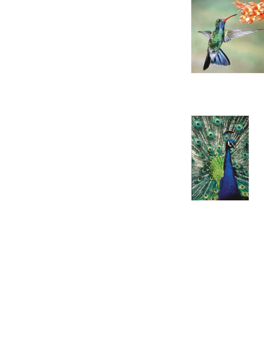
As with the hummingbird feathers

shown in the opening photograph,

the bright colors of peacock feathers

are also due to interference. In both

types of birds, structures in the

feathers split and recombine visible

light so that interference occurs for

certain colors.

Conditions for interference

©

Kolar

, Richard/Animals Animals/Earth Scenes

1178

C H A P T E R   37 •  Interference of Light Waves

source  produces  the  original  light  beam  and  the  two  slits  serve  only  to  separate  the
original beam into two parts (which, after all, is what is done to the sound signal from
the side-by-side loudspeakers at the end of the preceding section). Any random change
in  the  light  emitted  by  the  source  occurs  in  both  beams  at  the  same  time,  and  as  a 
result interference effects can be observed when the light from the two slits arrives at a
viewing screen.

If the light traveled only in its original direction after passing through the slits, as

shown in Figure 37.1a, the waves would not overlap and no interference pattern would
be seen. Instead, as we have discussed in our treatment of Huygens’s principle (Section
35.6), the waves spread out from the slits as shown in Figure 37.1b. In other words, the
light deviates from a straight-line path and enters the region that would otherwise be
shadowed.  As  noted  in  Section  35.3,  this  divergence  of  light  from  its  initial  line  of
travel is called 

diffraction.

Interference  in  light  waves  from  two  sources  was  first  demonstrated  by  Thomas

Young  in  1801.  A  schematic  diagram  of  the  apparatus  that  Young  used  is  shown  in
Figure 37.2a. Plane light waves arrive at a barrier that contains two parallel slits S

1

and

S

2

.  These  two  slits  serve  as  a  pair  of  coherent  light  sources  because  waves  emerging

from  them  originate  from  the  same  wave  front  and  therefore  maintain  a  constant
phase  relationship.  The  light  from  S

1

and  S

2

produces  on  a  viewing  screen  a  visible

pattern of bright and dark parallel bands called 

fringes (Fig. 37.2b). When the light

from S

1

and that from S

2

both arrive at a point on the screen such that constructive

interference occurs at that location, a bright fringe appears. When the light from the
two  slits  combines  destructively  at  any  location  on  the  screen,  a  dark  fringe  results.
Figure  37.3  is  a  photograph  of  an  interference  pattern  produced  by  two  coherent
vibrating sources in a water tank.

Figure  37.4  shows  some  of  the  ways  in  which  two  waves  can  combine  at  the

screen. In Figure 37.4a, the two waves, which leave the two slits in phase, strike the
screen  at  the  central  point  P.  Because  both  waves  travel  the  same  distance,  they
arrive  at  in  phase.  As  a  result,  constructive  interference  occurs  at  this  location,
and a bright fringe is observed. In Figure 37.4b, the two waves also start in phase,
but in this case the upper wave has to travel one wavelength farther than the lower

Figure 37.1 (a) If light waves did

not spread out after passing through

the slits, no interference would

occur. (b) The light waves from the

two slits overlap as they spread out,

filling what we expect to be

shadowed regions with light and

producing interference fringes on a

screen placed to the right of the slits.

At a beach in Tel Aviv, Israel, plane water waves pass through two openings in a

breakwall. Notice the diffraction effect—the waves exit the openings with circular wave

fronts, as in Figure 37.1b. Notice also how the beach has been shaped by the circular

wave fronts.

Courtesy of Sabina Zigman/Benjamin Cardozo High School

(a)

(b)

PITFALL PREVENTION 

37.1 Interference Patterns

Are Not Standing
Waves

The  interference  pattern  in
Figure  37.2b  shows  bright  and
dark  regions  that  appear  similar
to  the  antinodes  and  nodes  of  a
standing-wave pattern on a string
(Section  18.3).  While  both
patterns depend on the principle
of  superposition,  here  are  two
major differences: (1) waves on a
string  propagate  in  only  one
dimension  while  the  light-wave
interference  pattern  exists  in
three  dimensions;  (2)  the
standing-wave  pattern  represents
no net energy flow, while there is
a net energy flow from the slits to
the  screen  in  an  interference
pattern.

S E C T I O N   37. 2 •  Young’s Double-Slit Experiment

1179

wave to reach point Q. Because the upper wave falls behind the lower one by exactly
one wavelength, they still arrive in phase at , and so a second bright fringe appears
at  this  location.  At  point  in  Figure  37.4c,  however,  between  points  and  ,  the
upper  wave  has  fallen  half  a  wavelength  behind  the  lower  wave.  This  means  that
a trough  of  the  lower  wave  overlaps  a  crest  of  the  upper  wave;  this  gives  rise  to
destructive  interference  at  point  R.  For  this  reason,  a  dark  fringe  is  observed  at
this location.

S

1

S

2

Barrier

Viewing

screen

max

min

max

min

max

min

max

min

max

(a)

(b)

Active Figure 37.2 (a) Schematic diagram of Young’s double-slit experiment. Slits S

1

and S

2

behave as coherent sources of light waves that produce an interference pattern

on the viewing screen (drawing not to scale). (b) An enlargement of the center of a

fringe pattern formed on the viewing screen.

At the Active Figures link

at http://www.pse6.com, you

can adjust the slit separation

and the wavelength of the light

to see the effect on the

interference pattern.

A

B

Figure 37.3 An interference

pattern involving water waves is

produced by two vibrating

sources at the water’s surface. The

pattern is analogous to that

observed in Young’s double-slit

experiment. Note the regions of

constructive (A) and destructive

(B) interference.

Richard Megna/Fundamental Photographs

(a)

Bright

fringe

Dark

fringe

(b)

(c)

Bright

fringe

S

1

S

2

S

1

S

2

Slits

P

P

P

R

Q

 Viewing screen

Q

S

2

S

1

Figure 37.4 (a) Constructive interference occurs at point when the waves combine.

(b) Constructive interference also occurs at point Q. (c) Destructive interference

occurs at when the two waves combine because the upper wave falls half a wavelength

behind the lower wave. (All figures not to scale.)

M. Cagnet, M. Francon, J. C. Thier

We can describe Young’s experiment quantitatively with the help of Figure 37.5. The

viewing screen is located a perpendicular distance from the barrier containing two slits,
S

1

and S

2

. These slits are separated by a distance d, and the source is monochromatic. To

reach any arbitrary point in the upper half of the screen, a wave from the lower slit must
travel farther than a wave from the upper slit by a distance sin !. This distance is called
the 

path difference " (lowercase Greek delta). If we assume that r

1

and r

2

are parallel,

which is approximately true if is much greater than d, then " is given by

" #

r

2

$

r

1

#

sin!

(37.1)

The  value  of  " determines  whether  the  two  waves  are  in  phase  when  they  arrive  at
point P. If " is either zero or some integer multiple of the wavelength, then the two
waves  are  in  phase  at  point  and  constructive  interference  results.  Therefore,  the
condition for bright fringes, or 

constructive interference, at point is

(37.2)

The  number  is  called  the 

order  number. For constructive interference, the order

number is the same as the number of wavelengths that represents the path difference
between the waves from the two slits. The central bright fringe at ! # 0 is called the
zeroth-order  maximum. The  first  maximum  on  either  side,  where  # %1,  is  called  the
first-order maximum, and so forth.

When " is an odd multiple of &/2, the two waves arriving at point 

are 180° out of

phase  and  give  rise  to  destructive  interference.  Therefore,  the  condition  for  dark
fringes, or 

destructive interference, at point is

(37.3)

It is useful to obtain expressions for the positions along the screen of the bright

and dark fringes measured vertically from to P. In addition to our assumption that
'' d, we assume '' &. These can be valid assumptions because in practice is
often  on  the  order  of  1 m,  a  fraction  of  a  millimeter,  and  & a  fraction  of  a
micrometer for visible light. Under these conditions, ! is small; thus, we can use the
small  angle  approximation  sin!

! tan!.  Then,  from  triangle  OPQ in  Figure  37.5a,

d sin!

dark

#

((

1

2

)&


(# 0, %1, %2,


  )  )  ))

" #

d sin!


bright

#

m


&


(# 0, %1, %2,


  )  )  ))

1180

C H A P T E R   37 •  Interference of Light Waves

(b)

r

2

 – r

d sin

S

1

S

2

θ

d

r

1

r

2

(a)

d

S

1

S

2

Q

L

Viewing screen

θ

θ

P

O

δ

y

r

1

r

2

θ

Figure 37.5 (a) Geometric construction for describing Young’s double-slit experiment

(not to scale). (b) When we assume that r

1

is parallel to r

2

, the path difference between

the two rays is r

2

$

r

1

#

sin 

!

. For this approximation to be valid, it is essential that

'' d.

Path difference

Conditions for constructive

interference

Conditions for destructive

interference


Content   ..  293  294  295  296   ..