Physics For Scientists And Engineers 6E - part 294


  Index      Production     Physics For Scientists And Engineers 6E


Search            


Content   ..  292  293  294  295   ..


Physics For Scientists And Engineers 6E - part 294


Problems

1173

63. An  object  placed  10.0 cm  from  a  concave  spherical  mirror

produces a real image 8.00 cm from the mirror. If the object
is moved to a new position 20.0 cm from the mirror, what is
the position of the image? Is the latter image real or virtual?

64.

In  many  applications  it  is  necessary  to  expand  or  to
decrease  the  diameter  of  a  beam  of  parallel  rays  of  light.
This change can be made by using a converging lens and a
diverging  lens  in  combination.  Suppose  you  have  a  con-
verging lens of focal length 21.0 cm and a diverging lens of
focal length $ 12.0 cm. How can you arrange these lenses
to  increase  the  diameter  of  a  beam  of  parallel  rays?  By
what factor will the diameter increase?

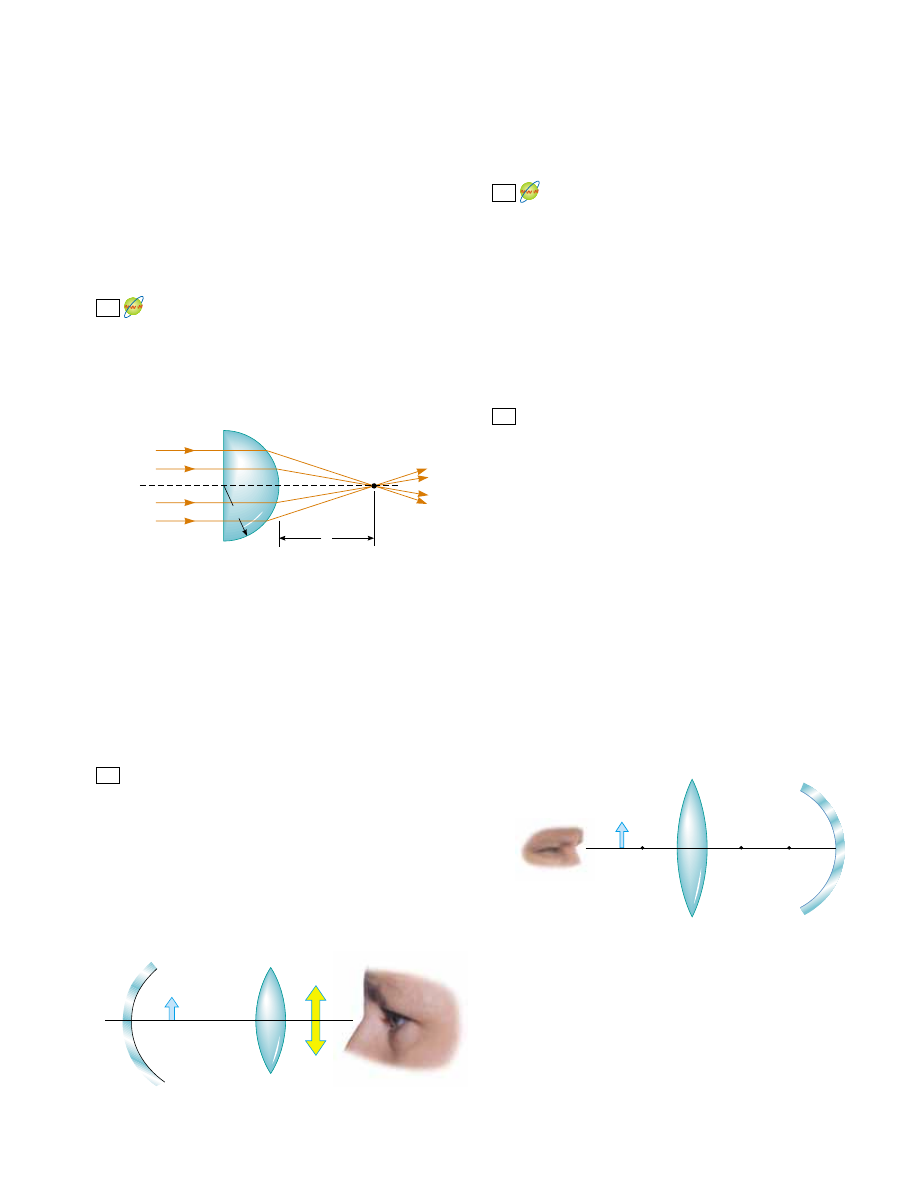
A  parallel  beam  of  light  enters  a  glass  hemisphere

perpendicular to the flat face, as shown in Figure P36.65.
The magnitude of the radius is 6.00 cm, and the index of
refraction is 1.560. Determine the point at which the beam
is focused. (Assume paraxial rays.)

65.

and the other is inverted. Both images are 1.50 times larger
than the object. The lens has a focal length of 10.0 cm. The
lens  and  mirror  are  separated  by  40.0 cm.  Determine  the
focal length of the mirror. Do not assume that the figure is
drawn to scale. 

The disk of the Sun subtends an angle of 0.533° at the

Earth.  What  are  the  position  and  diameter  of  the  solar
image formed by a concave spherical mirror with a radius
of curvature of 3.00 m?

70.

Assume the intensity of sunlight is 1.00 kW/m

2

at a particu-

lar  location.  A  highly  reflecting  concave  mirror  is  to  be
pointed toward the Sun to produce a power of at least 350 W
at the image. (a) Find the required radius R

a

of the circular

face area of the mirror. (b) Now suppose the light intensity is
to  be  at  least  120 kW/m

2

at  the  image.  Find  the  required

relationship between R

a

and the radius of curvature of the

mirror. The disk of the Sun subtends an angle of 0.533° at
the Earth.
In  a  darkened  room,  a  burning  candle  is  placed  1.50 m
from a white wall. A lens is placed between candle and wall
at  a  location  that  causes  a  larger,  inverted  image  to  form
on  the  wall.  When  the  lens  is  moved  90.0 cm  toward  the
wall, another image of the candle is formed. Find (a) the
two object distances that produce the specified images and
(b)  the  focal  length  of  the  lens.  (c)  Characterize  the
second image.

72.

Figure P36.72 shows a thin converging lens for which the
radii of curvature are R

1

"

9.00 cm and R

2

" $

11.0 cm.

The  lens  is  in  front  of  a  concave  spherical  mirror  with
the  radius  of  curvature  " 8.00 cm.  (a)  Assume  its
focal points  F

1

and  F

2

are  5.00 cm  from  the  center  of

the lens. Determine its index of refraction. (b) The lens
and  mirror  are  20.0 cm  apart,  and  an  object  is  placed
8.00 cm to the left of the lens. Determine the position of
the final image and its magnification as seen by the eye
in the figure. (c) Is the final image inverted or upright?
Explain.

71.

69.

n

R

Air

I

q

Figure P36.65

66.

Review problem. A spherical lightbulb of diameter 3.20 cm
radiates  light  equally  in  all  directions,  with  power  4.50 W.
(a)  Find  the  light  intensity  at  the  surface  of  the  bulb.
(b) Find the light intensity 7.20 m away from the center of
the bulb. (c) At this 7.20-m distance a lens is set up with its
axis pointing toward the bulb. The lens has a circular face
with a diameter 15.0 cm and has a focal length of 35.0 cm.
Find  the  diameter  of  the  image  of  the  bulb.  (d)  Find  the
light intensity at the image.
An object is placed 12.0 cm to the left of a diverging lens
of  focal  length  $ 6.00 cm.  A  converging  lens  of  focal
length 12.0 cm is placed a distance to the right of the di-
verging lens. Find the distance so that the final image is
at infinity. Draw a ray diagram for this case.

68.

An  observer  to  the  right  of  the  mirror–lens  combination
shown  in  Figure  P36.68  sees  two  real  images  that  are  the
same size and in the same location. One image is upright

67.

Object

Mirror

Lens

Images

Figure P36.68

F

2

C

F

1

Figure P36.72

73.

A compound microscope has an objective of focal length
0.300 cm  and  an  eyepiece  of  focal  length  2.50 cm.  If
an object  is  3.40 mm  from  the  objective,  what  is  the
magnification? (Suggestion: Use the lens equation for the
objective.)

74.

Two  converging  lenses  having  focal  lengths  of  10.0 cm
and  20.0 cm  are  located  50.0 cm  apart,  as  shown  in

1174

C H A P T E R   3 6 •  Image Formation

Figure P36.74. The final image is to be located between
the lenses  at  the  position  indicated.  (a)  How  far  to  the
left of the first lens should the object be? (b) What is the
overall  magnification?  (c)  Is  the  final  image  upright  or
inverted?

P36.76). If a strawberry is placed on the lower mirror, an
image of the strawberry is formed at the small opening at
the center of the top mirror. Show that the final image is
formed  at  that  location  and  describe  its  characteristics.
(Note: A  very  startling  effect  is  to  shine  a  flashlight  beam
on this image. Even at a glancing angle, the incoming light
beam  is  seemingly  reflected  from  the  image!  Do  you
understand why?)

77.

An object 2.00 cm high is placed 40.0 cm to the left of a
converging  lens  having  a  focal  length  of  30.0 cm.  A
diverging lens with a focal length of $ 20.0 cm is placed
110 cm  to  the  right  of  the  converging  lens.  (a)  Deter-
mine the position and magnification of the final image.
(b)  Is  the  image  upright  or  inverted?  (c)  What  If?
Repeat parts (a) and (b) for the case where the second
lens  is  a  converging  lens  having  a  focal  length  of
&

20.0 cm.

78.

Two lenses made of kinds of glass having different refractive
indices  n

1

and  n

2

are  cemented  together  to  form  what  is

called  an  optical  doublet.  Optical  doublets  are  often  used  to
correct  chromatic  aberrations  in  optical  devices.  The  first
lens of a doublet has one flat side and one concave side of
radius of curvature R. The second lens has two convex sides
of  radius  of  curvature  R.  Show  that  the  doublet  can  be
modeled as a single thin lens with a focal length described by

Answers to Quick Quizzes
36.1 
At C. A ray traced from the stone to the mirror and then

to observer 2 looks like this:

1

f

"

2n

2

$

n

1

$

1

R

f

2

 (20.0 cm)

f

1

 (10.0 cm)

Final image

Object

p

31.0 cm

50.0 cm

Figure P36.74

Strawberry

Small hole

Figure P36.76

© 

Michael Levin/Opti-Gone Associates

75.

A  cataract-impaired  lens  in  an  eye  may  be  surgically
removed and replaced by a manufactured lens. The focal
length  required  for  the  new  lens  is  determined  by
the lens-to-retina distance, which is measured by a sonar-
like  device,  and  by  the  requirement  that  the  implant
provide  for  correct  distant  vision.  (a)  Assuming  the
distance  from  lens  to  retina  is  22.4 mm,  calculate  the
power of the implanted lens in diopters. (b) Because no
accommodation  occurs  and  the  implant  allows  for
correct  distant  vision,  a  corrective  lens  for  close  work
or reading must  be  used.  Assume  a  reading  distance  of
33.0 cm  and  calculate  the  power  of  the  lens  in  the
reading glasses.

76.

A  floating  strawberry  illusion  is  achieved  with  two  para-
bolic  mirrors,  each  having  a  focal  length  7.50 cm,  facing
each  other  so  that  their  centers  are  7.50 cm  apart  (Fig.

C

2

1

36.2 False. The water spots are 2 m away from you and your

image is 4 m away. You cannot focus your eyes on both at
the same time.

36.3 (b).  A  concave  mirror  will  focus  the  light  from  a  large

area of the mirror onto a small area of the paper, result-
ing in a very high power input to the paper.

Answers to Quick Quizzes

1175

36.6 (a).  No  matter  where  is,  the  rays  refract  into  the  air

away from the normal and form a virtual image between
and the surface.

36.7 (b). Because the flat surfaces of the plane have infinite

radii  of  curvature,  Equation  36.15  indicates  that  the
focal  length  is  also  infinite.  Parallel  rays  striking
the plane focus at infinity, which means that they remain
parallel after passing through the glass.

36.8 (b). If there is a curve on the front surface, the refrac-

tion will differ at that surface when the mask is worn in
air and water. In order for there to be no difference in
refraction (for normal incidence), the front of the mask
should be flat.

36.9 (a). Because the light reflecting from a mirror does not

enter the material of the mirror, there is no opportunity
for  the  dispersion  of  the  material  to  cause  chromatic
aberration.

36.10 (a). If the object is brought closer to the lens, the image

moves  farther  away  from  the  lens,  behind  the  plane  of
the  film.  In  order  to  bring  the  image  back  up  to  the
film, the lens is moved toward the object and away from
the film.

36.11 (c). The Sun’s rays must converge onto the paper. A far-

sighted person wears converging lenses.

n

1

 < n

2

I

n

2

R

O

q

p

n

1

36.4 (b). A convex mirror always forms an image with a mag-

nification less than one, so the mirror must be concave.
In  a  concave  mirror,  only  virtual  images  are  upright.
This  particular  photograph  is  of  the  Hubble  Space
Telescope primary mirror.

36.5 (d). When is far away, the rays refract into the mater-

ial of index n

2

and converge to form a real image as in

Figure 36.18. For certain combinations of and n

2

as O

moves very close to the refracting surface, the incident
angle  of  the  rays  increases  so  much  that  rays  are  no
longer  refracted  back  toward  the  principal  axis.  This 
results in a virtual image as shown below:

Chapter 37

Interference of Light Waves

C H A P T E R   O U T L I N E

37.1 Conditions for Interference

37.2 Young’s Double-Slit

Experiment

37.3 Intensity Distribution of the

Double-Slit Interference
Pattern

37.4 Phasor Addition of Waves

37.5 Change of Phase Due to

Reflection

37.6 Interference in Thin Films

37.7 The Michelson Interferometer

1176

The colors in many of a hummingbird’s feathers are not due to pigment. The iridescence

that makes the brilliant colors that often appear on the throat and belly is due to an
interference effect caused by structures in the feathers. The colors will vary with the viewing
angle. (RO-MA/Index Stock Imagery)


Content   ..  292  293  294  295   ..