Physics For Scientists And Engineers 6E - part 260


  Index      Production     Physics For Scientists And Engineers 6E


Search            


Content   ..  258  259  260  261   ..


Physics For Scientists And Engineers 6E - part 260


the resistor. Because this rate is proportional to the square of the current, it makes no
difference  whether  the  current  is  direct  or  alternating—that  is,  whether  the  sign
associated with the current is positive or negative. However, the temperature increase
produced by an alternating current having a maximum value I

max

is not the same as

that produced by a direct current equal to I

max

. This is because the alternating current

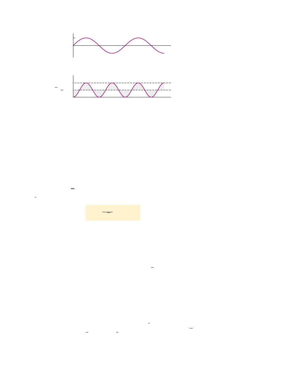
is at this maximum value for only an instant during each cycle (Fig. 33.5a). What is of
importance  in  an  AC  circuit  is  an  average  value  of  current,  referred  to  as  the 

rms

current. As  we  learned  in  Section  21.1,  the  notation  rms stands  for  root-mean-square,
which in this case means the square root of the mean (average) value of the square of
the current: 

. Because i

2

varies as sin

2

#

and because the average value of i

2

is  I

2

max

(see Fig. 33.5b), the rms current is

1

(33.4)

This  equation  states  that  an  alternating  current  whose  maximum  value  is  2.00 A
delivers  to  a  resistor  the  same  power  as  a  direct  current  that  has  a  value  of
(0.707)(2.00 A) " 1.41 A.  Thus,  the  average  power  delivered  to  a  resistor  that
carries an alternating current is

!

av

"

I

2

rms

R

I


rms

"

I


max

2

"

0.707I


max

1

2

I


rms

"

i

2

S E C T I O N   3 3 . 2 •  Resistors in an AC Circuit

1037

Figure 33.5 (a) Graph of the current in a resistor as a function of time. (b) Graph of

the current squared in a resistor as a function of time. Notice that the gray shaded

regions under the curve and above the dashed line for I

2

max

/2 have the same area as the

gray shaded regions above the curve and below the dashed line for I

2

max

/2. Thus, the

average value of i

2

is I

2

max

/2.

1

That the square root of the average value of i

2

is equal to 

can be shown as follows.

The  current  in  the  circuit  varies  with  time  according  to  the  expression  I

max

sin

#

t,  so

i

2

"

I

2

max

sin

2

#

t. Therefore, we can find the average value of i

2

by calculating the average value

of sin

2

#

t. A graph of cos

2

#

versus time is identical to a graph of sin

2

#

versus time, except that

the  points  are  shifted  on  the  time  axis.  Thus,  the  time  average  of  sin

2

#

is  equal  to  the  time

average of cos

2

#

when taken over one or more complete cycles. That is,

(sin

2

#

t)

av

"

(cos

2

#

t)

av

Using this fact and the trigonometric identity sin

2

&

$

cos

2

&

"

1, we obtain

(sin

2

#

t)

av

$

(cos

2

#

t)

av

"

2(sin

2

#

t)

av

"

1

(sin

2

#

t)

av

"

When  we  substitute  this  result  in  the  expression  i

2

"

I

2

max

sin

2

#

t,  we  obtain  (i

2

)

av

"

"

I

2

rms

"

I

2

max

/2, or I

rms

"

I

max

/ . The factor 

is valid only for sinusoidally varying currents.

Other waveforms, such as sawtooth variations, have different factors.

1/

2

2

i

2

1

2

I


max


/

2

I

max

I

2

i

2

I

2

1

2

t

t

(a)

(b)

i

=

i

2

max

max

0

0

rms current

Average power delivered to

a resistor

Alternating voltage is also best discussed in terms of rms voltage, and the relation-

ship is identical to that for current:

(33.5)

When we speak of measuring a 120-V alternating voltage from an electrical outlet, we are
referring to an rms voltage of 120 V. A quick calculation using Equation 33.5 shows that
such an alternating voltage has a maximum value of about 170 V. One reason we use rms
values  when  discussing  alternating  currents  and  voltages  in  this  chapter  is that  AC
ammeters and voltmeters are designed to read rms values. Furthermore, with rms values,
many of the equations we use have the same form as their direct current counterparts.

V


rms

"

V


max

2

"

0.707 

V


max

1038

C H A P T E R   3 3 •  Alternating Current Circuits

rms voltage

Active Figure 33.6 A circuit

consisting of an inductor of

inductance connected to an AC

source.

At the Active Figures link

at http://www.pse6.com, you

can adjust the inductance, the

frequency, and the maximum

voltage. The results can be

studied with the graph and

phasor diagram in Figure 33.7.

Quick  Quiz  33.3

Which  of  the  following  statements  might  be  true  for  a

resistor connected to a sinusoidal AC source? (a) !

av

"

0 and i

av

"

0 (b) !

av

"

0 and

i

av

'

0 (c) !

av

'

0 and i

av

"

0 (d) !

av

'

0 and i

av

'

0.

Example 33.1 What Is the rms Current?

The voltage output of an AC source is given by the expres-
sion !" (200 V) sin #t. Find the rms current in the circuit
when this source is connected to a 100-( resistor.

Solution Comparing  this  expression  for  voltage  output
with  the  general  form  !" !V

max

sin #t,  we  see  that

!

V

max

"

200 V. Thus, the rms voltage is

Therefore,

1.41 A

I


rms

"

!

V


rms

R

"

141 V

100 (

"

!

V


rms

"

!

V


max

2

"

200 V

2

"

141 V

33.3 Inductors in an AC Circuit

Now consider an AC circuit consisting only of an inductor connected to the terminals
of an AC source, as shown in Figure 33.6. If !v

L

"

)

L

" *

L(di/dt) is the self-induced

instantaneous  voltage  across  the  inductor  (see  Eq.  32.1),  then  Kirchhoff’s  loop  rule
applied to this circuit gives !$ !v

L

"

0, or

When we substitute !V

max

sin #for !and rearrange, we obtain

(33.6)

Solving this equation for di, we find that

Integrating  this  expression

2

gives  the  instantaneous  current  i

L

in  the  inductor  as  a

function of time:

(33.7)

i

L

"

V


max

L


!

 sin #t dt " *

V


max

#

L

  cos #

t

di "

V

max

L

  sin #t dt

L  

di
dt

"

V


max

 sin #t

L  

di
dt

"

0

L

v

L

v = V

max

 sin 

   t

ω

2

We  neglect  the  constant  of  integration  here  because  it  depends  on  the  initial  conditions,

which are not important for this situation.

When  we  use  the  trigonometric  identity  cos  #" * sin(#* %/2),  we  can  express
Equation 33.7 as

(33.8)

Comparing  this  result  with  Equation  33.6,  we  see  that  the  instantaneous  current  i

L

in the inductor and the instantaneous voltage !v

L

across the inductor are out of phase

by (%/2) rad " 90°.

A plot of voltage and current versus time is provided in Figure 33.7a. In general,

inductors in an AC circuit produce a current that is out of phase with the AC voltage.
For  example,  when  the  current  i

L

in  the  inductor  is  a  maximum  (point  in  Figure

33.7a), it is momentarily not changing, so the voltage across the inductor is zero (point
d). At points like and e, the current is zero and the rate of change of current is at a
maximum. Thus, the voltage across the inductor is also at a maximum (points and ).
Note that the voltage reaches its maximum value one quarter of a period before the
current reaches its maximum value. Thus, we see that

i

L

"

V


max

#

L

  sin 

"

#

*

%

2

#

S E C T I O N   3 3 . 3 •  Inductors in an AC Circuit

1039

At the Active Figures link

at http://www.pse6.com, you

can adjust the inductance, the

frequency, and the maximum

voltage of the circuit in Figure

33.6. The results can be studied

with the graph and phasor

diagram in this figure.

Current in an inductor

(a)

i

L

v

L

V

max

t

v

L

i

L

I

max

V

max

i

L

v

L

t

(b)

ω

a

c

d

b

e

T

I

max

f

Active Figure 33.7 (a) Plots of the instantaneous current i

L

and instantaneous voltage

!

v

L

across an inductor as functions of time. The current lags behind the voltage by 90°.

(b) Phasor diagram for the inductive circuit, showing that the current lags behind the

voltage by 90°. 

for a sinusoidal applied voltage, the current in an inductor always lags behind the
voltage across the inductor by 90° (one-quarter cycle in time).

As  with  the  relationship  between  current  and  voltage  for  a  resistor,  we  can

represent this relationship for an inductor with a phasor diagram as in Figure 33.7b.
Notice  that  the  phasors  are  at  90° to  one  another,  representing  the  90° phase
difference between current and voltage.

From  Equation  33.7  we  see  that  the  current  in  an  inductive  circuit  reaches  its

maximum value when cos #

" * 1:

(33.9)

This looks similar to the relationship between current, voltage, and resistance in a DC
circuit,  " !V/(Eq.  27.8).  In  fact,  because  I

max

has  units  of  amperes  and  !V

max

has units  of  volts,  #must  have  units  of  ohms.  Therefore,  #has  the  same  units  as
resistance and is related to current and voltage in the same way as resistance. It must
behave in a manner similar to resistance, in the sense that it represents opposition to
the flow of charge. Notice that because #

depends on the applied frequency #, the

inductor  reacts differently,  in  terms  of  offering  resistance  to  current,  for  different

I


max

"

V


max

#

L

Maximum current in an inductor

frequencies. For this reason, we define #as the 

inductive reactance:

(33.10)

and we can write Equation 33.9 as

(33.11)

The expression for the rms current in an inductor is similar to Equation 33.9, with I

max

replaced by I

rms

and !V

max

replaced by !V

rms

.

Equation 33.10 indicates that, for a given applied voltage, the inductive reactance

increases as the frequency increases. This is consistent with Faraday’s law—the greater
the rate of change of current in the inductor, the larger is the back emf. The larger
back emf translates to an increase in the reactance and a decrease in the current.

Using Equations 33.6 and 33.11, we find that the instantaneous voltage across the

inductor is

(33.12)

v

L

" *

L  

di
dt

" *

V

max

 sin #" *I


max


X

L

 sin #t

I


max

"

V


max

X

L

X

L 


#

L

1040

C H A P T E R   3 3 •  Alternating Current Circuits

Inductive reactance

Quick Quiz 33.4

Consider the AC circuit in Figure 33.8. The frequency of

the  AC  source  is  adjusted  while  its  voltage  amplitude  is  held  constant.  The  lightbulb
will glow the brightest at (a) high frequencies (b) low frequencies (c) The brightness
will be the same at all frequencies.

Figure 33.8 (Quick Quiz 33.4) At what frequencies will the bulb glow the brightest?

L

R

Example 33.2 A Purely Inductive AC Circuit

In a purely inductive AC circuit (see Fig. 33.6), " 25.0 mH
and the rms voltage is 150 V. Calculate the inductive reactance
and rms current in the circuit if the frequency is 60.0 Hz.

Solution Equation 33.10 gives

X

L

"

#

" 2%fL " 2%(60.0 Hz)(25.0 + 10

*

3

H)

From an rms version of Equation 33.11, the rms current is

15.9 A

I


rms

"

!

V


,


rms

X

L

"

150 V

9.42 (

"

9.42 (

"

What If?

What if the frequency increases to 6.00 kHz? What

happens to the rms current in the circuit?

Answer If  the  frequency  increases,  the  inductive  reactance
increases because the current is changing at a higher rate. The
increase in inductive reactance results in a lower current.

Let us calculate the new inductive reactance:

X

L

2%(6.00 + 10

3

Hz)(25.0 + 10

*

3

H) " 942 (

The new current is

I


rms

"

150 V

942 (

"

0.159 A

Voltage across an inductor


Content   ..  258  259  260  261   ..