Physics For Scientists And Engineers 6E - part 259


  Index      Production     Physics For Scientists And Engineers 6E


Search            


Content   ..  257  258  259  260   ..


Physics For Scientists And Engineers 6E - part 259


1033

Alternating Current Circuits

C H A P T E R   O U T L I N E

33.1 AC Sources

33.2 Resistors in an AC Circuit

33.3 Inductors in an AC Circuit

33.4 Capacitors in an AC Circuit

33.5 The 

RLC

Series Circuit

33.6 Power in an AC Circuit

33.7 Resonance in a Series 

RLC

Circuit

33.8 The Transformer and Power

Transmission

33.9 Rectifiers and Filters

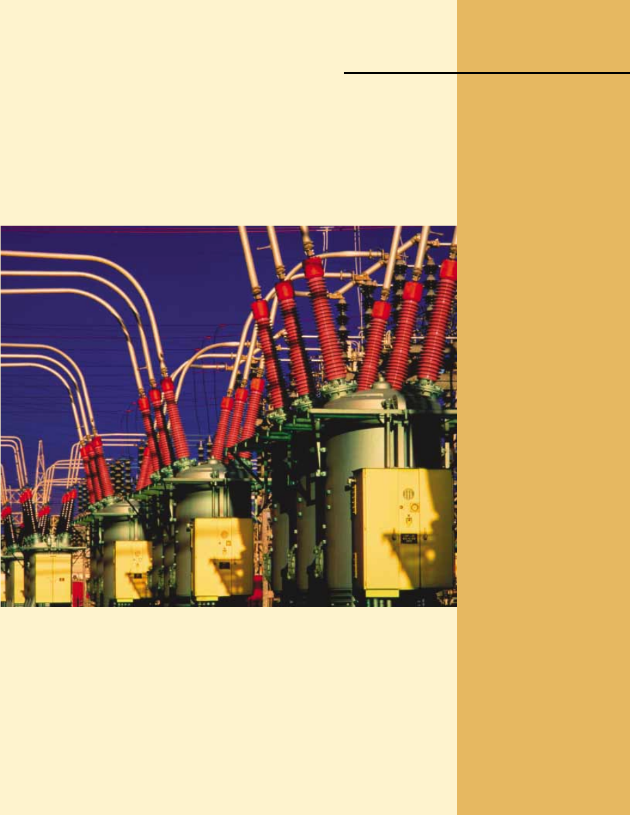
These large transformers are used to increase the voltage at a power plant for distribution

of energy by electrical transmission to the power grid. Voltages can be changed relatively
easily because power is distributed by alternating current rather than direct current. (Lester
Lefkowitz/Getty Images)

Chapter 33

1034

I

n this chapter we describe alternating current (AC) circuits. Every time we turn on a

television set, a stereo, or any of a multitude of other electrical appliances in a home,
we are calling on alternating currents to provide the power to operate them. We begin
our  study  by  investigating  the  characteristics  of  simple  series  circuits  that  contain
resistors, inductors, and capacitors and that are driven by a sinusoidal voltage. We shall
find  that  the  maximum  alternating  current  in  each  element  is  proportional  to  the
maximum  alternating  voltage  across  the  element.  In  addition,  when  the  applied
voltage is sinusoidal, the current in each element is also sinusoidal, but not necessarily
in phase with the applied voltage. The primary aim of this chapter can be summarized
as follows: if an AC source applies an alternating voltage to a series circuit containing
resistors, inductors, and capacitors, we want to know the amplitude and time character-
istics of the alternating current. We conclude the chapter with two sections concerning
transformers, power transmission, and electrical filters.

33.1 AC Sources

An AC circuit consists of circuit elements and a power source that provides an alternat-
ing voltage !v. This time-varying voltage is described by

!

" !V

max

sin #t

where  !V

max

is  the  maximum  output  voltage  of  the  AC  source,  or  the 

voltage

amplitude. There  are  various  possibilities  for  AC  sources,  including  generators,  as
discussed  in  Section  31.5,  and  electrical  oscillators.  In  a  home,  each  electrical  outlet
serves as an AC source.

From Equation 15.12, the angular frequency of the AC voltage is

where is the frequency of the source and is the period. The source determines the
frequency of the current in any circuit connected to it. Because the output voltage of
an AC source varies sinusoidally with time, the voltage is positive during one half of the
cycle and negative during the other half, as in Figure 33.1. Likewise, the current in any
circuit  driven  by  an  AC  source  is  an  alternating  current  that  also  varies  sinusoidally
with  time.  Commercial  electric-power  plants  in  the  United  States  use  a  frequency  of
60 Hz, which corresponds to an angular frequency of 377 rad/s.

33.2 Resistors in an AC Circuit

Consider a simple AC circuit consisting of a resistor and an AC source 

, as

shown in Figure 33.2. At any instant, the algebraic sum of the voltages around a closed
loop  in  a  circuit  must  be  zero  (Kirchhoff’s  loop  rule).  Therefore,  !$ !v

R

"

0,  so

# "

2%"

2%

T

PITFALL PREVENTION 

33.1 Time-Varying Values

We  will  use  lowercase  symbols
!

and to indicate the instanta-

neous  values  of  time-varying
voltages  and  currents.  Capital
letters  represent  fixed  values  of
voltage  and  current,  such  as
!

V

max

and I

max

.

v

V

max

t

T

Figure 33.1 The voltage supplied

by an AC source is sinusoidal with a

period T.

that the magnitude of the source voltage equals the magnitude of the voltage across
the resistor:

!

" !v

R

" !

V

max

sin #t

(33.1)

where  !v

R

is  the 

instantaneous  voltage  across  the  resistor. Therefore,  from

Equation 27.8, " !V/I, the instantaneous current in the resistor is

(33.2)

where I

max

is the maximum current:

From Equations 33.1 and 33.2, we see that the instantaneous voltage across the resistor is

!

v

R

"

I

max

sin #t

(33.3)

A plot of voltage and current versus time for this circuit is shown in Figure 33.3a. At

point  a,  the  current  has  a  maximum  value  in  one  direction,  arbitrarily  called  the
positive direction. Between points and b, the current is decreasing in magnitude but
is still in the positive direction. At b, the current is momentarily zero; it then begins to
increase in the negative direction between points and c. At c, the current has reached
its maximum value in the negative direction.

The current and voltage are in step with each other because they vary identically

with  time.  Because  i

R

and  !v

R

both  vary  as  sin #and  reach  their  maximum  values

at the  same  time,  as  shown  in  Figure  33.3a,  they  are  said  to  be 

in  phase, similar  to

the way  that  two  waves  can  be  in  phase,  as  discussed  in  our  study  of  wave  motion  in

I


max

"

V


max

R

i

R

"

v

R

R

"

V


max

R


sin #I


max

 sin #t

S E C T I O N   3 3 . 2 •  Resistors in an AC Circuit

1035

R

v

R

v = V

max

 sin 

   t

ω

At the Active Figures link

at http://www.pse6.com, you

can adjust the resistance, the

frequency, and the maximum

voltage. The results can be

studied with the graph and

phasor diagram in Figure 33.3.

Active Figure 33.2 A circuit consisting of a resistor of

resistance connected to an AC source, designated by the

symbol 

.

(b)

i

R

,

v

R

i

R

v

R

I

max

V

max

t

(a)

i

R

,

v

R

I

max

V

max

i

R

v

R

t

ω

a

b

c

T

Maximum current in a resistor

Voltage across a resistor

At the Active Figures link

at http://www.pse6.com, you

can adjust the resistance, the

frequency, and the maximum

voltage of the circuit in Figure

33.2. The results can be studied

with the graph and phasor

diagram in this figure.

Active Figure 33.3 (a) Plots of the instantaneous current i

R

and instantaneous voltage

!

v

R

across a resistor as functions of time. The current is in phase with the voltage,

which means that the current is zero when the voltage is zero, maximum when the

voltage is maximum, and minimum when the voltage is minimum. At time T, one

cycle of the time-varying voltage and current has been completed. (b) Phasor diagram

for the resistive circuit showing that the current is in phase with the voltage.

Chapter  18.  Thus, 

for  a  sinusoidal  applied  voltage,  the  current  in  a  resistor  is

always  in  phase  with  the  voltage  across  the  resistor. For resistors in AC circuits,
there are no new concepts to learn. Resistors behave essentially the same way in both
DC and AC circuits. This will not be the case for capacitors and inductors.

To  simplify  our  analysis  of  circuits  containing  two  or  more  elements,  we  use

graphical  constructions  called  phasor  diagrams. 

phasor is  a  vector  whose  length  is

proportional  to  the  maximum  value  of  the  variable  it  represents  (!V

max

for  voltage

and I

max

for current in the present discussion) and which rotates counterclockwise at

an angular  speed  equal  to  the  angular  frequency  associated  with  the  variable.  The
projection  of  the  phasor  onto  the  vertical  axis  represents  the  instantaneous  value  of
the quantity it represents.

Figure  33.3b  shows  voltage  and  current  phasors  for  the  circuit  of  Figure  33.2  at

some instant of time. The projections of the phasor arrows onto the vertical axis are
determined by a sine function of the angle of the phasor with respect to the horizontal
axis. For example, the projection of the current phasor in Figure 33.3b is I

max

sin #t.

Notice that this is the same expression as Equation 33.2. Thus, we can use the projec-
tions of phasors to represent current values that vary sinusoidally in time. We can do
the same with time-varying voltages. The advantage of this approach is that the phase
relationships  among  currents  and  voltages  can  be  represented  as  vector  additions  of
phasors, using our vector addition techniques from Chapter 3.

In the case of the single-loop resistive circuit of Figure 33.2, the current and voltage

phasors lie along the same line, as in Figure 33.3b, because i

R

and !v

R

are in phase.

The current and voltage in circuits containing capacitors and inductors have different
phase relationships.

1036

C H A P T E R   3 3 •  Alternating Current Circuits

Quick Quiz 33.1

Consider the voltage phasor in Figure 33.4, shown at three

instants  of  time.  Choose  the  part  of  the  figure  that  represents  the  instant  of  time  at
which the instantaneous value of the voltage has the largest magnitude.

Quick Quiz 33.2

For the voltage phasor in Figure 33.4, choose the part of

the figure that represents the instant of time at which the instantaneous value of the
voltage has the smallest magnitude.

Figure 33.4 (Quick Quizzes 33.1 and 33.2) A voltage phasor is shown at three instants

of time.

PITFALL PREVENTION 

33.2 We’ve Seen This Idea

Before

To  help  with  this  discussion  of
phasors,  review  Section  15.4,  in
which we represented the simple
harmonic motion of a real object
to  the  projection  of  uniform
circular  motion  of  an  imaginary
object  onto  a  coordinate  axis.
Phasors are a direct analog to this
discussion.

(a)

(b)

(c)

For the simple resistive circuit in Figure 33.2, note that 

the average value of the

current  over  one  cycle  is  zero. That  is,  the  current  is  maintained  in  the  positive
direction for the same amount of time and at the same magnitude as it is maintained
in the negative direction. However, the direction of the current has no effect on the
behavior  of  the  resistor.  We  can  understand  this  by  realizing  that  collisions  between
electrons  and  the  fixed  atoms  of  the  resistor  result  in  an  increase  in  the  resistor’s
temperature.  Although  this  temperature  increase  depends  on  the  magnitude  of  the
current, it is independent of the direction of the current.

We can make this discussion quantitative by recalling that the rate at which energy

is delivered to a resistor is the power ! " i

2

R, where is the instantaneous current in


Content   ..  257  258  259  260   ..