Physics For Scientists And Engineers 6E - part 256
 

  Index      Production     Physics For Scientists And Engineers 6E


Search            


Content   ..  254  255  256  257   ..


Physics For Scientists And Engineers 6E - part 256


S E C T I O N   3 2 . 6 •  The RLC Circuit

1021

block–spring system is, from Equation 15.31,

(32.30)

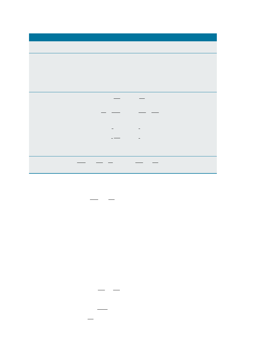
Comparing Equations 32.29 and 32.30, we see that corresponds to the position of
the block at any instant, to the mass of the block, to the damping coefficient b,
and to 1/k, where is the force constant of the spring. These and other relationships
are listed in Table 32.1.

Because  the  analytical  solution  of  Equation  32.29  is  cumbersome,  we  give  only  a

qualitative description of the circuit behavior. In the simplest case, when " 0, Equa-
tion 32.29 reduces to that of a simple LC circuit, as expected, and the charge and the
current oscillate sinusoidally in time. This is equivalent to removal of all damping in
the mechanical oscillator.

When is small, a situation analogous to light damping in the mechanical oscilla-

tor, the solution of Equation 32.29 is

(32.31)

where 1

d

, the angular frequency at which the circuit oscillates, is given by

(32.32)

That is, the value of the charge on the capacitor undergoes a damped harmonic oscil-
lation in analogy with a block–spring system moving in a viscous medium. From Equa-
tion 32.32, we see that, when **

(so that the second term in the brackets is

much smaller than the first), the frequency 1

d

of the damped oscillator is close to that

of the undamped oscillator, 

. Because dQ /dt, it follows that the current also

1/

LC

4L/C

1

d

"

&

1

LC

#

"

R

2L

#

2

'

1/2

 Q


max

 e

#

Rt/2L

 cos 1

d

t

m  

d

2

x

dt

2

,

b  

dx

dt

  , kx " 0

One-Dimensional

Electric Circuit

Mechanical System

Charge

Position

Current

Velocity

Potential difference

Force

Resistance

Viscous damping 

coefficient

Capacitance

(" spring constant)

Inductance

Mass

Current " time

Velocity " time

derivative of charge

derivative of 

position

Rate of change of

Acceleration "

current " second

second time

time derivative

derivative of

of charge

position

Energy in inductor

Kinetic energy of

moving object

Energy in capacitor

Potential energy

stored in a spring

Rate of energy loss

Rate of energy loss

due to resistance

due to friction

RLC circuit

Damped object on

a spring

Analogies Between Electrical and Mechanical Systems

Table 32.1

x

v

x

%

F

x

b

4 1/k
m

L  

d

2

Q

dt

2

,

R  

dQ

dt

,

Q

C

"

0

  4     

d

2

x

dt

2

,

b  

dx

dt

,

kx " 0

I

2

R

  4   b


v


2

 U

C

"

1

2


Q

2

C

  4   "

1

2


kx


 U

L

"

1

2

 LI

2

  4   "

1

2


mv


dI

dt

"

d

2

Q

dt

2


4


a

x

"

dv

x

dt

"

d

2

x

dt

2

"

dQ

dt

  4   v

x

"

dx

dt

undergoes  damped  harmonic  oscillation.  A  plot  of  the  charge  versus  time  for  the
damped  oscillator  is  shown  in  Figure  32.23a.  Note  that  the  maximum  value  of  Q
decreases after each oscillation, just as the amplitude of a damped block–spring system
decreases in time.

When we consider larger values of R, we find that the oscillations damp out more

rapidly; in fact, there exists a critical resistance value 

above which no oscil-

lations occur. A system with R

c

is said to be critically damped. When exceeds R

c

,

the system is said to be overdamped (Fig. 32.24).

R

c

"

4L/C

1022

C H A P T E R   3 2 •  Inductance

Q

max

Q

0

t

(a)

Active Figure 32.23 (a) Charge versus time for a damped RLC circuit. The charge

decays in this way when -

. The Q-versus-curve represents a plot of

Equation 32.31. (b) Oscilloscope pattern showing the decay in the oscillations of an

RLC circuit.

4L/C

Courtesy of J. Rudmin

Q

t

>   4L/C

Q

max

Figure 32.24 Plot of versus for

an overdamped RLC circuit, which

occurs for values of -

4L/C

When the current in a coil changes with time, an emf is induced in the coil according
to Faraday’s law. The 

self-induced emf is

(32.1)

where is the 

inductance of the coil. Inductance is a measure of how much opposi-

tion a coil offers to a change in the current in the coil. Inductance has the SI unit of
henry (H), where 1 H " 1 V & s / A .

The inductance of any coil is

(32.2)

where $

B

is the magnetic flux through the coil and is the total number of turns. The

inductance of a device depends on its geometry. For example, the inductance of an air-
core solenoid is

(32.4)

where is the cross-sectional area, and ! is the length of the solenoid.

If  a  resistor  and  inductor  are  connected  in  series  to  a  battery  of  emf 

!

,  and  if  a

switch  in  the  circuit  is  open  for  * 0  and  then  closed  at  " 0,  the  current  in  the
circuit varies in time according to the expression

(32.7)

"

!

R

 (1 # e

#

t/+


)

"

'

0

N

2

A

!


"

N


$

B

I

!

L

" #

L  

dI
dt

S U M M A R Y

Take a practice test for

this chapter by clicking on
the Practice Test link at
http://www.pse6.com.

At the Active Figures link

at http://www.pse6.com, you

can observe this graph develop

for the damped RLC circuit in

Figure 32.21.

(b)

Summary

1023

where + " L/R is the 

time constant of the RL circuit. That is, the current increases to

an equilibrium value of 

!

/after a time interval that is long compared with +. If the

battery in the circuit is replaced by a resistanceless wire, the current decays exponen-
tially with time according to the expression

(32.10)

where 

!

/is the initial current in the circuit.

The energy stored in the magnetic field of an inductor carrying a current is

(32.12)

This energy is the magnetic counterpart to the energy stored in the electric field of a
charged capacitor.

The energy density at a point where the magnetic field is is

(32.14)

The 

mutual inductance of a system of two coils is given by

(32.15)

This mutual inductance allows us to relate the induced emf in a coil to the changing
source current in a nearby coil using the relationships

(32.16, 32.17)

In an LC circuit that has zero resistance and does not radiate electromagnetically

(an  idealization),  the  values  of  the  charge  on  the  capacitor  and  the  current  in  the
circuit vary in time according to the expressions

(32.21)

(32.23)

where Q

max

is the maximum charge on the capacitor, 2 is a phase constant, and 1 is

the angular frequency of oscillation:

(32.22)

The energy in an LC circuit continuously transfers between energy stored in the capacitor
and energy stored in the inductor. The total energy of the LC circuit at any time is

(32.26)

At " 0, all of the energy is stored in the electric field of the capacitor (Q

2

max

/2).

Eventually, all of this energy is transferred to the inductor (LI

2

max

/2). However, the

total energy remains constant because energy transformations are neglected in the ideal
LC circuit.

In an RLC circuit with small resistance, the charge on the capacitor varies with time

according to

(32.31)

where

(32.32)

1

d

"

&

1

LC

#

"

R

2L

#

2

'

1/2

 Q


max

 e

#

Rt/2L

 cos 1

d

t

U

C

,

U

L

"

Q

2

max

2C

 cos

2

 1,

L


I

2

max

2

 sin

2

 1t

1 "

1

LC

"

dQ

dt

" #

1

Q


max

 sin(1, 2)

Q


max

 cos(1, 2)

!

2

" #

M


dI


1

dt


and


!

1

" #

M


dI


2

dt

M

12

"

N


2


$

12

I

1

"

M

21

"

N

1


$

21

I

2

"

M

u

B

"

B


2

2'

0

"

1

2

 L


I


2

"

!

R

 e

#

t/+

1024

C H A P T E R   3 2 •  Inductance

1. Why is the induced emf that appears in an inductor called

a “counter” or “back” emf ?
The  current  in  a  circuit  containing  a  coil,  resistor,  and
battery has reached a constant value. Does the coil have an
inductance? Does the coil affect the value of the current?

3. What parameters affect the inductance of a coil? Does the

inductance of a coil depend on the current in the coil?

4. How can a long piece of wire be wound on a spool so that

the wire has a negligible self-inductance?

5. For  the  series  RL circuit  shown  in  Figure  Q32.5,  can  the

back emf ever be greater than the battery emf ? Explain.

2.

8. Consider  this  thesis:  “Joseph  Henry,  America’s  first  profes-

sional  physicist,  caused  the  most  recent  basic  change  in
the human  view  of  the  Universe  when  he  discovered  self-
induction during a school vacation at the Albany Academy
about  1830.  Before  that  time,  one  could  think  of  the
Universe as composed of just one thing: matter. The energy
that  temporarily  maintains  the  current  after  a  battery  is
removed from a coil, on the other hand, is not energy that
belongs to any chunk of matter. It is energy in the massless
magnetic field surrounding the coil. With Henry’s discovery,
Nature  forced  us  to  admit  that  the  Universe  consists  of 
fields as well as matter.” Argue for or against the statement.
What in your view comprises the Universe?
If  the  current  in  an  inductor  is  doubled,  by  what  factor
does the stored energy change?

10. Discuss  the  similarities  between  the  energy  stored  in  the

electric field of a charged capacitor and the energy stored
in the magnetic field of a current-carrying coil.

11. What  is  the  inductance  of  two  inductors  connected  in

series? Does it matter if they are solenoids or toroids?

12. The centers of two circular loops are separated by a fixed

distance. For what relative orientation of the loops is their
mutual inductance a maximum? a minimum? Explain.

13. Two solenoids are connected in series so that each carries

the  same  current  at  any  instant.  Is  mutual  induction
present? Explain.
In the LC circuit shown in Figure 32.16, the charge on the
capacitor  is  sometimes  zero,  but  at  such  instants  the
current in the circuit is not zero. How is this possible?

15. If the resistance of the wires in an LC circuit were not zero,

would the oscillations persist? Explain.

16. How can you tell whether an RLC circuit is overdamped or

underdamped?

17. What  is  the  significance  of  critical  damping  in  an  RLC

circuit?

18. Can an object exert a force on itself? When a coil induces

an emf in itself, does it exert a force on itself?

14.

9.

Q U E S T I O N S

ε

R

L

Switch

Figure Q32.5 Questions 5 and 6.

Figure Q32.7

6. Suppose the switch in Figure Q32.5 has been closed for a

long  time  and  is  suddenly  opened.  Does  the  current
instantaneously drop to zero? Why does a spark appear at
the switch contacts at the moment the switch is opened?

7. A  switch  controls  the  current  in  a  circuit  that  has  a  large

inductance. Is a spark (see Figure Q32.7) more likely to be
produced at the switch when the switch is being closed or
when it is being opened, or doesn’t it matter? The electric
arc can melt and oxidize the contact surfaces, resulting in
high resistivity of the contacts and eventual destruction of
the  switch.  Before  electronic  ignitions  were  invented,
distributor  contact  points  in  automobiles  had  to  be
replaced regularly. Switches in power distribution networks
and  switches  controlling  large  motors,  generators,  and
electromagnets  can  suffer  from  arcing  and  can  be  very
dangerous to operate.


Content   ..  254  255  256  257   ..