Physics For Scientists And Engineers 6E - part 218
28.3 Kirchhoff’s Rules
As we saw in the preceding section, simple circuits can be analyzed using the expres-
sion "V # IR and the rules for series and parallel combinations of resistors. Very
often, however, it is not possible to reduce a circuit to a single loop. The procedure
for analyzing more complex circuits is greatly simplified if we use two principles called
Kirchhoff ’s rules:
SECTION 28.3 • Kirchhoff’s Rules
869
lightbulb, a small jumper loop covered by an insulating
material is wrapped around the filament leads. When the
filament fails and 120 V appears across the bulb, an arc
burns the insulation on the jumper and connects the
filament leads. This connection now completes the circuit
through the bulb even though its filament is no longer
active (Fig. 28.13).
Suppose that all the bulbs in a 50-bulb miniature-light
string are operating. A 2.40-V potential drop occurs across
each bulb because the bulbs are in series. A typical power
input to this style of bulb is 0.340 W. The filament resis-
tance of each bulb at the operating temperature is
(2.40 V)
2
/(0.340 W) # 16.9 '. The current in each bulb is
2.40 V/16.9 ' # 0.142 A. When a bulb fails, the resistance
across its terminals is reduced to zero because of the alternate
jumper connection mentioned in the preceding paragraph.
All the other bulbs not only stay on but glow more brightly
because the total resistance of the string is reduced and con-
sequently the current in each bulb increases.
Let us assume that the resistance of a bulb remains at
16.9 ' even though its temperature rises as a result of the
increased current. If one bulb fails, the potential difference
across each of the remaining bulbs increases to 120 V/49 #
2.45 V, the current increases from 0.142 A to 0.145 A, and the
power increases to 0.355 W. As more bulbs fail, the current
keeps rising, the filament of each bulb operates at a higher
temperature, and the lifetime of the bulb is reduced. For this
reason, you should check for failed (nonglowing) bulbs in
such a series-wired string and replace them as soon as possible,
in order to maximize the lifetimes of all the bulbs.
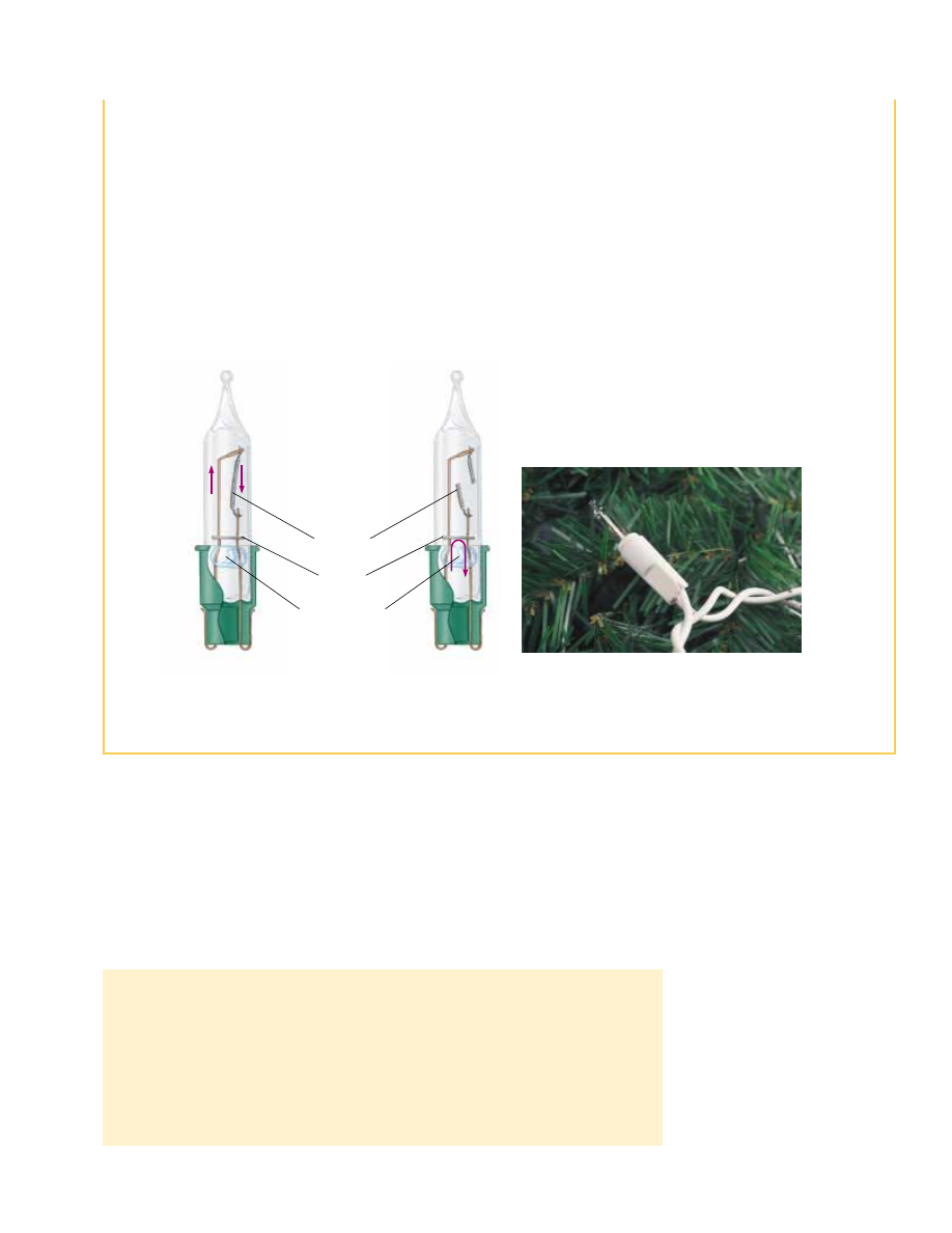
Figure 28.13 (a) Schematic diagram of a modern “miniature” holiday lightbulb, with a
jumper connection to provide a current path if the filament breaks. When the filament
is intact, charges flow in the filament. (b) A holiday lightbulb with a broken filament.
In this case, charges flow in the jumper connection. (c) A Christmas-tree lightbulb.
George Semple
Filament
Jumper
Glass insulator
(b)
(a)
I
I
I
1.
Junction rule. The sum of the currents entering any junction in a circuit must
equal the sum of the currents leaving that junction:
(28.9)
2.
Loop rule. The sum of the potential differences across all elements around any
closed circuit loop must be zero:
(28.10)
#
closed
loop
"V # 0
#
I
in
#
#
I
out
(c)