Physics For Scientists And Engineers 6E - part 217
An extension of this analysis to three or more resistors in parallel gives
(28.8)
We can see from this expression that
the inverse of the equivalent resistance of two
or more resistors connected in parallel is equal to the sum of the inverses of the
individual resistances. Furthermore, the equivalent resistance is always less
than the smallest resistance in the group.
Household circuits are always wired such that the appliances are connected in par-
allel. Each device operates independently of the others so that if one is switched off,
the others remain on. In addition, in this type of connection, all of the devices operate
on the same voltage.
1
R
eq
#
1
R
1
%
1
R
2
%
1
R
3
% ( ( (
SECTION 28.2 • Resistors in Series and Parallel
865
The equivalent resistance of
several resistors in parallel
Quick Quiz 28.5
In Figure 28.4, imagine that we add a third resistor in series
with the first two. Does the current in the battery (a) increase, (b) decrease, or
(c) remain the same? Does the terminal voltage of the battery (d) increase,
(e) decrease, or (f) remain the same?
Quick Quiz 28.6
In Figure 28.6, imagine that we add a third resistor in
parallel with the first two. Does the current in the battery (a) increase, (b) decrease,
or (c) remain the same? Does the terminal voltage of the battery (d) increase,
(e) decrease, or (f) remain the same?
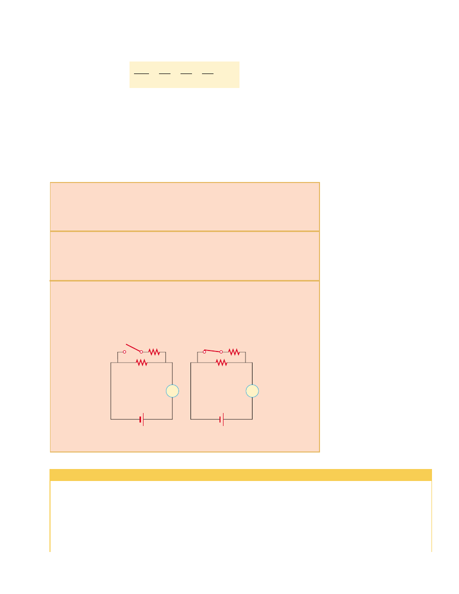
Quick Quiz 28.7
With the switch in the circuit of Figure 28.7 open (left),
there is no current in R
2
. There is current in R
1
and this current is measured with the
ammeter at the right side of the circuit. If the switch is closed (Fig. 28.7, right), there is
current in R
2
. What happens to the reading on the ammeter when the switch is closed?
(a) the reading goes up; (b) the reading goes down; (c) the reading does not change.
Switch open
R
1
R
2
Switch closed
A
R
1
R
2
A
Figure 28.7 (Quick Quiz 28.7) What happens when the switch is closed?
Conceptual Example 28.3 Landscape Lights
A homeowner wishes to install 12-volt landscape lighting
in his back yard. To save money, he purchases inexpensive
18-gauge cable, which has a relatively high resistance per
unit length. This cable consists of two side-by-side wires
separated by insulation, like the cord on an appliance.
He runs a 200-foot length of this cable from the power
supply to the farthest point at which he plans to position a
light fixture. He attaches light fixtures across the two wires
on the cable at 10-foot intervals, so the light fixtures are in
parallel. Because of the cable’s resistance, the brightness
of the bulbs in the light fixtures is not as desired. Which
problem does the homeowner have? (a) All of the bulbs
glow equally less brightly than they would if lower-
resistance cable had been used. (b) The brightness of the
bulbs decreases as you move farther from the power
supply.