Physics For Scientists And Engineers 6E - part 200
 

  Index      Production     Physics For Scientists And Engineers 6E


Search            


Content   ..  198  199  200  201   ..


Physics For Scientists And Engineers 6E - part 200


Note that by definition capacitance is always a positive quantity. Furthermore, the charge
and  the  potential  difference  !are  always  expressed  in  Equation  26.1  as  positive
quantities. Because the potential difference increases linearly with the stored charge,
the ratio /!is constant for a given capacitor. Therefore, capacitance is a measure
of a capacitor’s ability to store charge. Because positive and negative charges are sepa-
rated in the system of two conductors in a capacitor, there is electric potential energy
stored in the system.

From Equation 26.1, we see that capacitance has SI units of coulombs per volt. The

SI unit of capacitance is the 

farad (F), which was named in honor of Michael Faraday:

The farad is a very large unit of capacitance. In practice, typical devices have capaci-
tances  ranging  from  microfarads  (10

$

6

F)  to  picofarads  (10

$

12

F).  We  shall  use  the

symbol  %F  to  represent  microfarads.  To  avoid  the  use  of  Greek  letters,  in  practice,
physical capacitors often are labeled “mF’’ for microfarads and “mmF’’ for micromicro-
farads or, equivalently, “pF’’ for picofarads.

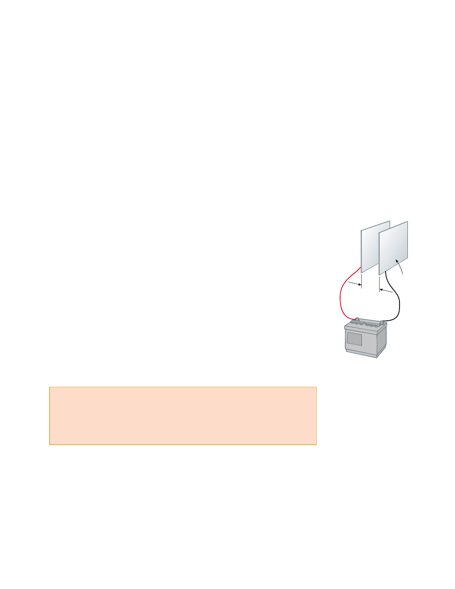
Let  us  consider  a  capacitor  formed  from  a  pair  of  parallel  plates,  as  shown  in

Figure  26.2.  Each  plate  is  connected  to  one  terminal  of  a  battery,  which  acts  as
a source  of  potential  difference.  If  the  capacitor  is  initially  uncharged,  the  battery
establishes an electric field in the connecting wires when the connections are made.
Let  us  focus  on  the  plate  connected  to  the  negative  terminal  of  the  battery.  The
electric  field  applies  a  force  on  electrons  in  the  wire  just  outside  this  plate;  this
force causes  the  electrons  to  move  onto  the  plate.  This  movement  continues  until
the plate, the wire, and the terminal are all at the same electric potential. Once this
equilibrium  point  is  attained,  a  potential  difference  no  longer  exists  between  the
terminal and the plate, and as a result no electric  field is present in the wire, and
the movement of electrons stops. The plate now carries a negative charge. A similar
process occurs at the other capacitor plate, with electrons moving from the plate to
the wire, leaving the plate positively charged. In this final configuration, the poten-
tial difference across the capacitor plates is the same as that between the terminals
of the battery.

Suppose that we have a capacitor rated at 4 pF. This rating means that the capaci-

tor  can  store  4 pC  of  charge  for  each  volt  of  potential  difference  between  the  two
conductors. If a 9-V battery is connected across this capacitor, one of the conductors
ends  up  with  a  net  charge  of  $ 36 pC  and  the  other  ends  up  with  a  net  charge  of
&

36 pC.

1 F # 1 C/V

SECTION 26.2 •  Calculating Capacitance

797

Quick Quiz 26.1

A capacitor stores charge at a potential difference !V. If

the voltage applied by a battery to the capacitor is doubled to 2 !V, (a) the capacitance
falls to half its initial value and the charge remains the same (b) the capacitance and
the charge both fall to half their initial values (c) the capacitance and the charge both
double (d) the capacitance remains the same and the charge doubles.

d

Q

+Q

Area = A

+

Figure 26.2 A parallel-plate capac-

itor consists of two parallel con-

ducting plates, each of area A,

separated by a distance d. When

the capacitor is charged by con-

necting the plates to the terminals

of a battery, the plates carry equal

amounts of charge. One plate

carries positive charge, and the

other carries negative charge.

PITFALL PREVENTION 

26.2 Potential Difference

is !V, not V

We  use  the  symbol  !for 
the  potential  difference  across 
a  circuit  element  or  a  device
because this is consistent with our
definition  of  potential  difference
and with the meaning of the delta
sign.  It  is  a  common,  but  confus-
ing,  practice  to  use  the  symbol  V
without the delta sign for a poten-
tial difference. Keep this in mind
if you consult other texts.

PITFALL PREVENTION 

26.3 Too Many C’s

Do not confuse italic for capac-
itance  with  non-italic  C  for  the
unit coulomb.

26.2 Calculating Capacitance

We can derive an expression for the capacitance of a pair of oppositely charged con-
ductors in the following manner: assume a charge of magnitude , and calculate the
potential  difference  using  the  techniques  described  in  the  preceding  chapter.  We
then use the expression /!to evaluate the capacitance. As we might expect,
we  can  perform  this  calculation  relatively  easily  if  the  geometry  of  the  capacitor  is
simple.

While the most common situation is that of two conductors, a single conductor also

has a capacitance. For example, imagine a spherical charged conductor. The electric
field  lines  around  this  conductor  are  exactly  the  same  as  if  there  were  a  conducting
shell of infinite radius, concentric with the sphere and carrying a charge of the same
magnitude but opposite sign. Thus, we can identify the imaginary shell as the second
conductor of a two-conductor capacitor. We now calculate the capacitance for this situ-
ation.  The  electric  potential  of  the  sphere  of  radius  is  simply  k

e

/R,  and  setting

# 0 for the infinitely large shell, we have

(26.2)

This  expression  shows  that  the  capacitance  of  an  isolated  charged  sphere  is  propor-
tional to its radius and is independent of both the charge on the sphere and the poten-
tial difference.

The capacitance of a pair of conductors depends on the geometry of the conduc-

tors. Let us illustrate this with three familiar geometries, namely, parallel plates, con-
centric  cylinders,  and  concentric  spheres.  In  these  examples,  we  assume  that  the
charged  conductors  are  separated  by  a  vacuum.  The  effect  of  a  dielectric  material
placed between the conductors is treated in Section 26.5.

Parallel-Plate Capacitors

Two parallel metallic plates of equal area are separated by a distance d, as shown
in  Figure  26.2.  One  plate  carries  a  charge  ,  and  the  other  carries  a  charge  $ .
Let us consider how the geometry of these conductors influences the capacity of the
combination  to  store  charge.  Recall  that  charges  of  the  same  sign  repel  one
another. As a capacitor is being charged by a battery, electrons flow into the nega-
tive plate and out of the positive plate. If the capacitor plates are large, the accumu-
lated  charges  are  able  to  distribute  themselves  over  a  substantial  area,  and  the
amount  of  charge  that  can  be  stored  on  a  plate  for  a  given  potential  difference
increases as the plate area is increased. Thus, we expect the capacitance to be pro-
portional to the plate area A.

Now  let  us  consider  the  region  that  separates  the  plates.  If  the  battery  has  a

constant potential difference between its terminals, then the electric field between
the plates must increase as is decreased. Let us imagine that we move the plates
closer  together  and  consider  the  situation  before  any  charges  have  had  a  chance
to move  in  response  to  this  change.  Because  no  charges  have  moved,  the  electric
field  between  the  plates  has  the  same  value  but  extends  over  a  shorter  distance.
Thus,  the  magnitude  of  the  potential  difference  between  the  plates  !Ed (Eq.
25.6)  is  now  smaller.  The  difference  between  this  new  capacitor  voltage  and  the
terminal voltage of the battery now exists as a potential difference across the wires
connecting  the  battery  to  the  capacitor.  This  potential  difference  results  in  the
electric  field  in  the  wires  that  drives  more  charge  onto  the  plates,  increasing  the
potential  difference  between  the  plates.  When  the  potential  difference  between
the plates again matches that of the battery, the potential difference across the wires
falls  back to  zero,  and  the  flow  of  charge  stops.  Thus,  moving  the  plates  closer
together causes the charge on the capacitor to increase. If is increased, the charge
decreases. As a result, we expect the capacitance of the pair of plates to be inversely
proportional to d.

We  can  verify  these  physical  arguments  with  the  following  derivation.  The

surface charge  density  on  either  plate  is  ' #

/A. If  the  plates  are  very  close

together  (in  comparison  with  their  length  and  width),  we  can  assume  that  the
electric  field  is  uniform  between  the  plates  and  is  zero  elsewhere.  According
to the

What  If? feature  in  Example  24.8,  the  value  of  the  electric  field  between

#

Q

!

V

#

Q

k

e


Q


/R

#

R

k

e

#

4()

0

R

798

C H A P T E R   2 6 •  Capacitance and Dielectrics

Capacitance of an isolated

charged sphere

the plates is

Because the field between the plates is uniform, the magnitude of the potential differ-
ence between the plates equals Ed (see Eq. 25.6); therefore,

Substituting this result into Equation 26.1, we find that the capacitance is

(26.3)

That is, 

the capacitance of a parallel-plate capacitor is proportional to the area

of  its  plates  and  inversely  proportional  to  the  plate  separation, just  as  we  ex-
pected from our conceptual argument.

A  careful  inspection  of  the  electric  field  lines  for  a  parallel-plate  capacitor

reveals that the field is uniform in the central region between the plates, as shown
in Figure 26.3a. However, the field is nonuniform at the edges of the plates. Figure
26.3b is a photograph of the electric field pattern of a parallel-plate capacitor. Note
the  nonuniform  nature  of  the  electric  field  at  the  ends  of  the  plates.  Such  end
effects can be neglected if the plate separation is small compared with the length of
the plates.

Figure  26.4  shows  a  battery  connected  to  a  single  parallel-plate  capacitor  with  a

switch in the circuit. Let us identify the circuit as a system. When the switch is closed,
the battery establishes an electric field in the wires and charges flow between the wires
and the capacitor. As this occurs, there is a transformation of energy within the system.
Before  the  switch  is  closed,  energy  is  stored  as  chemical  energy  in  the  battery.  This
energy  is  transformed  during  the  chemical  reaction  that  occurs  within  the  battery
when  it  is  operating  in  an  electric  circuit.  When  the  switch  is  closed,  some  of  the
chemical energy in the battery is converted to electric potential energy related to the
separation of positive and negative charges on the plates. As a result, we can describe a
capacitor as a device that stores energy as well as charge. We will explore this energy
storage in more detail in Section 26.4.

#

)

0

A

d

#

Q

!

V

#

Q

Qd/)

0

A

!

Ed #

Qd

)

0

A

#

'

)

0

#

Q

)

0

A

SECTION 26.2 •  Calculating Capacitance

799

+Q

Q

(a)

Courtesy of Harold M. W

aage, Princeton University

Figure 26.3 (a) The electric field between the plates of a parallel-plate capacitor is

uniform near the center but nonuniform near the edges. (b) Electric field pattern of

two oppositely charged conducting parallel plates. Small pieces of thread on an oil

surface align with the electric field.

Capacitance of parallel plates

(b)

800

C H A P T E R   2 6 •  Capacitance and Dielectrics

Example 26.1 Parallel-Plate Capacitor

A  parallel-plate  capacitor  with  air  between  the  plates  has  an
area # 2.00 * 10

$

4

m

2

and a plate separation # 1.00 mm.

Find its capacitance.

Solution From Equation 26.3, we find that

1.77 pF

  # 1.77 * 10

$

12


F #

#

)

0

A

d

#

(8.85 * 10

$

12

 C

2

/N+m

2

)(2.00 * 10

$

4

 m

2

)

1.00 * 10

$

3

 m

+

(b)

+

+

+

+

+

+

V

Chemical

energy in

battery is

reduced

Electric

field in

wire

Electric

field in

wire

Electric

field between

plates

E

Electrons

move

from the

wire to

the plate

Separation

of charges

represents

potential

energy

Electrons move

from the plate

to the wire,

leaving the plate

positively

charged

+

(a)

V

Active Figure 26.4 (a) A circuit consisting of a capacitor, a battery, and a switch.

(b) When the switch is closed, the battery establishes an electric field in the wire

that causes electrons to move from the left plate into the wire and into the right plate

from the wire. As a result, a separation of charge exists on the plates, which represents

an increase in electric potential energy of the system of the circuit. This energy in the

system has been transformed from chemical energy in the battery.

At the Active Figures link

at http://www.pse6.com, you

can adjust the battery voltage

and see the resulting charge on

the plates and the electric field

between the plates.

Quick  Quiz  26.2

Many  computer  keyboard  buttons  are  constructed  of

capacitors,  as  shown  in  Figure  26.5.  When  a  key  is  pushed  down,  the  soft  insulator
between the movable plate and the fixed plate is compressed. When the key is pressed,
the  capacitance  (a)  increases,  (b)  decreases,  or  (c)  changes  in  a  way  that  we  cannot
determine because the complicated electric circuit connected to the keyboard button
may cause a change in !V.

Figure 26.5 (Quick Quiz 26.2) One type of com-

puter keyboard button.

Key

Movable

plate

Soft

insulator

Fixed

plate

B


Content   ..  198  199  200  201   ..