Physics For Scientists And Engineers 6E - part 196


  Index      Production     Physics For Scientists And Engineers 6E


Search            


Content   ..  194  195  196  197   ..


Physics For Scientists And Engineers 6E - part 196


SECTION 25.7 •  The Millikan Oil-Drop Experiment

781

these  free  electrons  with  the  ionized  air  molecules.  If  a  conductor  has  an  irregular
shape, the electric field can be very high near sharp points or edges of the conductor;
consequently,  the  ionization  process  and  corona  discharge  are  most  likely  to  occur
around such points.

Corona discharge is used in the electrical transmission industry to locate broken or

faulty components. For example, a broken insulator on a transmission tower has sharp
edges where corona discharge is likely to occur. Similarly, corona discharge will occur
at the sharp end of a broken conductor strand. Observation of these discharges is diffi-
cult because the visible radiation emitted is weak and most of the radiation is in the
ultraviolet. (We will discuss ultraviolet radiation and other portions of the electromag-
netic spectrum in Section 34.6.) Even use of traditional ultraviolet cameras is of little
help  because  the  radiation  from  the  corona  discharge  is  overwhelmed  by  ultraviolet
radiation  from  the  Sun.  Newly  developed  dual-spectrum  devices  combine  a  narrow-
band  ultraviolet  camera  with  a  visible  light  camera  to  show  a  daylight  view  of  the
corona  discharge  in  the  actual  location  on  the  transmission  tower  or  cable.  The
ultraviolet part of the camera is designed to operate in a wavelength range in which
radiation from the Sun is very weak.

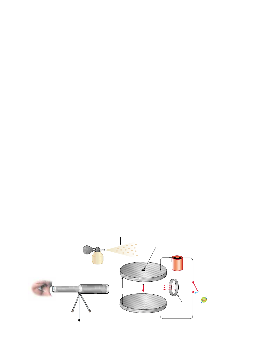
25.7 The Millikan Oil-Drop Experiment

During  the  period  from  1909  to  1913,  Robert  Millikan  performed  a  brilliant  set  of
experiments in which he measured e, the magnitude of the elementary charge on an
electron,  and  demonstrated  the  quantized  nature  of  this  charge.  His  apparatus,
diagrammed  in  Figure  25.27,  contains  two  parallel  metallic  plates.  Oil  droplets  from
an atomizer are allowed to pass through a small hole in the upper plate. Millikan used
x-rays to ionize the air in the chamber, so that freed electrons would adhere to the oil
drops,  giving  them  a  negative  charge.  A  horizontally  directed  light  beam  is  used  to
illuminate  the  oil  droplets,  which  are  viewed  through  a  telescope  whose  long  axis  is
perpendicular  to  the  light  beam.  When  the  droplets  are  viewed  in  this  manner,  they
appear  as  shining  stars  against  a  dark  background,  and  the  rate  at  which  individual
drops fall can be determined.

Let us assume that a single drop having a mass and carrying a charge is being

viewed and that its charge is negative. If no electric field is present between the plates,

Telescope

Oil droplets

Illumination

Pin hole

d

q

v

+

Active Figure 25.27 Schematic drawing of the Millikan oil-drop apparatus.

At the Active Figures link

at http://www.pse6.com, you

can do a simplified version of

the experiment for yourself. You

will be able to take data on a

number of oil drops and deter-

mine the elementary charge

from your data.

the two forces acting on the charge are the gravitational force m

g acting downward

4

and  a  viscous  drag  force 

F

D

acting  upward  as  indicated  in  Figure  25.28a.  The  drag

force is proportional to the drop’s speed. When the drop reaches its terminal speed v,
the two forces balance each other (mg F

D

).

Now suppose that a battery connected to the plates sets up an electric field between

the plates such that the upper plate is at the higher electric potential. In this case, a third
force q

E acts on the charged drop. Because is negative and E is directed downward,

this  electric  force  is  directed  upward,  as  shown  in  Figure  25.28b.  If  this  force  is  suffi-
ciently great, the drop moves upward and the drag force 

F

D

2

acts downward. When the

upward electric force q

E balances the sum of the gravitational force and the downward

drag force 

F

D

2

, the drop reaches a new terminal speed v2 in the upward direction.

With  the  field  turned  on,  a  drop  moves  slowly  upward,  typically  at  rates  of  hun-

dredths of a centimeter per second. The rate of fall in the absence of a field is compa-
rable. Hence, one can follow a single droplet for hours, alternately rising and falling,
by simply turning the electric field on and off.

After recording measurements on thousands of droplets, Millikan and his co-workers

found that all droplets, to within about 1% precision, had a charge equal to some integer
multiple of the elementary charge :

where  # 1.60 % 10

!

19

C.  Millikan’s  experiment  yields  conclusive  evidence  that

charge is quantized. For this work, he was awarded the Nobel Prize in Physics in 1923.

25.8 Applications of Electrostatics

The practical application of electrostatics is represented by such devices as lightning
rods  and  electrostatic  precipitators  and  by  such  processes  as  xerography  and  the
painting  of  automobiles.  Scientific  devices  based  on  the  principles  of  electrostatics
include  electrostatic  generators,  the  field-ion  microscope,  and  ion-drive  rocket
engines.

The Van de Graaff Generator

Experimental results show that when a charged conductor is placed in contact with the
inside of a hollow conductor, all of the charge on the charged conductor is transferred
to  the  hollow  conductor.  In  principle,  the  charge  on  the  hollow  conductor  and  its
electric potential can be increased without limit by repetition of the process.

In  1929  Robert  J.  Van  de  Graaff  (1901–1967)  used  this  principle  to  design  and

build an electrostatic generator. This type of generator is used extensively in nuclear
physics research. A schematic representation of the generator is given in Figure 25.29.
Charge is delivered continuously to a high-potential electrode by means of a moving
belt  of  insulating  material.  The  high-voltage  electrode  is  a  hollow  metal  dome
mounted on an insulating column. The belt is charged at point by means of a corona
discharge between comb-like metallic needles and a grounded grid. The needles are
maintained at a positive electric potential of typically 10

4

V. The positive charge on the

moving  belt  is  transferred  to  the  dome  by  a  second  comb  of  needles  at  point  B.
Because the electric field inside the dome is negligible, the positive charge on the belt
is easily transferred to the conductor regardless of its potential. In practice, it is possi-
ble  to  increase  the  electric  potential  of  the  dome  until  electrical  discharge  occurs
through the air. Because the “breakdown’’ electric field in air is about 3 % 10

6

V/m, a

ne


# 0, !1, !2, !3,

  .  .  .

782

C H A P T E R   2 5 •  Electric Potential

F

D

F

D

qE

mg

E

v

(b) Field on

v

mg

q

(a) Field off

Figure 25.28 The forces acting on

a negatively charged oil droplet in

the Millikan experiment.

4

There is also a buoyant force on the oil drop due to the surrounding air. This force can be incorpo-

rated as a correction in the gravitational force m

g on the drop, so we will not consider it in our analysis.

SECTION 25.8 •  Applications of Electrostatics

783

sphere 1 m in radius can be raised to a maximum potential of 3 % 10

6

V. The potential

can  be  increased  further  by  increasing  the  radius  of  the dome  and  by  placing  the
entire system in a container filled with high-pressure gas.

Van de Graaff generators can produce potential differences as large as 20 million

volts.  Protons  accelerated  through  such  large  potential  differences  receive  enough
energy  to  initiate  nuclear  reactions  between  themselves  and  various  target  nuclei.
Smaller  generators  are  often  seen  in  science  classrooms  and  museums.  If  a  person
insulated from the ground touches the sphere of a Van de Graaff generator, his or her
body  can  be  brought  to  a  high  electric  potential.  The  hair  acquires  a  net  positive
charge, and each strand is repelled by all the others, as in the opening photograph of
Chapter 23.

The Electrostatic Precipitator

One important application of electrical discharge in gases is the electrostatic precipitator.
This  device  removes  particulate  matter  from  combustion  gases,  thereby  reducing  air
pollution. Precipitators are especially useful in coal-burning power plants and in indus-
trial  operations  that  generate  large  quantities  of  smoke.  Current  systems  are  able  to
eliminate more than 99% of the ash from smoke.

Figure  25.30a  shows  a  schematic  diagram  of  an  electrostatic  precipitator.  A  high

potential  difference  (typically  40  to  100 kV)  is  maintained  between  a  wire  running
down the center of a duct and the walls of the duct, which are grounded. The wire is
maintained  at  a  negative  electric  potential  with  respect  to  the  walls,  so  the  electric
field is directed toward the wire. The values of the field near the wire become high
enough to cause a corona discharge around the wire; the air near the wire contains
positive ions, electrons, and such negative ions as O

2

!

. The air to be cleaned enters

the duct and moves near the wire. As the electrons and negative ions created by the
discharge are accelerated toward the outer wall by the electric field, the dirt particles
in the air become charged by collisions and ion capture. Because most of the charged
dirt particles are negative, they too are drawn to the duct walls by the electric field.
When  the  duct  is  periodically  shaken,  the  particles  break  loose  and  are  collected  at
the bottom.

In addition to reducing the level of particulate matter in the atmosphere (compare

Figs.  25.30b  and  c),  the  electrostatic  precipitator  recovers  valuable  materials  in  the
form of metal oxides.

Metal dome

Belt

Ground

B

A

+

P

Insulator

+

+

+
+
+
+
+
+
+
+
+
+
+
+
+

+

+

+

+

+

+

+

+

+

+

Figure 25.29 Schematic diagram

of a Van de Graaff generator. Charge

is transferred to the metal dome at

the top by means of a moving belt.

The charge is deposited on the belt

at point and transferred to the

hollow conductor at point B.

(a)

Insulator

Clean air

out

Weight

Dirty

air in

Dirt out

(c)

(b)

Figure 25.30 (a) Schematic diagram of an electrostatic precipitator. The high negative

electric potential maintained on the central coiled wire creates a corona discharge in

the vicinity of the wire. Compare the air pollution when the electrostatic precipitator is

(b) operating and (c) turned off.

Rei O’Hara/Black Star/PNI

Greig Cranna/Stock, Boston/PNI

Xerography and Laser Printers

The  basic  idea  of  xerography

5

was  developed  by  Chester  Carlson,  who  was  granted

a patent for the xerographic process in 1940. The unique feature of this process is the
use of a photoconductive material to form an image. (A photoconductor is a material that
is  a  poor  electrical  conductor  in  the  dark  but  becomes  a  good  electrical  conductor
when exposed to light.)

The xerographic process is illustrated in Figure 25.31a to d. First, the surface of a

plate or drum that has been coated with a thin film of photoconductive material (usu-
ally selenium or some compound of selenium) is given a positive electrostatic charge
in  the  dark.  An  image  of  the  page  to  be  copied  is  then  focused  by  a  lens  onto  the
charged  surface.  The  photoconducting  surface  becomes  conducting  only  in  areas
where light strikes it. In these areas, the light produces charge carriers in the photo-
conductor  that  move  the  positive  charge  off  the  drum.  However,  positive  charges
remain  on  those  areas  of  the  photoconductor  not  exposed  to  light,  leaving  a  latent
image of the object in the form of a positive surface charge distribution.

Next, a negatively charged powder called a toner is dusted onto the photoconducting

surface. The charged powder adheres only to those areas of the surface that contain the
positively charged image. At this point, the image becomes visible. The toner (and hence
the image) is then transferred to the surface of a sheet of positively charged paper.

Finally, the toner is “fixed’’ to the surface of the paper as the toner melts while passing

through high-temperature rollers. This results in a permanent copy of the original.

A laser printer (Fig. 25.31e) operates by the same principle, with the exception that a

computer-directed laser beam is used to illuminate the photoconductor instead of a lens.

784

C H A P T E R   2 5 •  Electric Potential

5

The prefix xero - is from the Greek word meaning “dry.’’ Note that liquid ink is not used in xerography.

Selenium-coated

drum

(a) Charging the drum

(b) Imaging the document

(d) Transferring the

       toner to the paper

Laser

beam

Interlaced pattern

of laser lines

(e) Laser printer drum

Negatively

charged

toner

(c) Applying the toner

Lens

Light causes some areas

of drum to become

electrically conducting,

removing positive charge

Figure 25.31 The xerographic process: (a) The photoconductive surface of the drum

is positively charged. (b) Through the use of a light source and lens, an image is

formed on the surface in the form of positive charges. (c) The surface containing the

image is covered with a negatively charged powder, which adheres only to the image

area. (d) A piece of paper is placed over the surface and given a positive charge. This

transfers the image to the paper as the negatively charged powder particles migrate to

the paper. The paper is then heat-treated to “fix’’ the powder. (e) A laser printer oper-

ates similarly except the image is produced by turning a laser beam on and off as it

sweeps across the selenium-coated drum.


Content   ..  194  195  196  197   ..