Physics For Scientists And Engineers 6E - part 138
 

  Index      Production     Physics For Scientists And Engineers 6E


Search            


Content   ..  136  137  138  139   ..


Physics For Scientists And Engineers 6E - part 138


for constructive interference

and

(18.2)

for destructive interference

This  discussion  enables  us  to  understand  why  the  speaker  wires  in  a  stereo  system

should be connected properly. When connected the wrong way—that is, when the posi-
tive (or red) wire is connected to the negative (or black) terminal on one of the speakers
and the other is correctly wired—the speakers are said to be “out of phase”—one speaker
cone moves outward while the other moves inward. As a consequence, the sound wave
coming from one speaker destructively interferes with the wave coming from the other—
along  a  line  midway  between  the  two,  a  rarefaction  region  due  to  one  speaker  is
superposed on a compression region from the other speaker. Although the two sounds
probably do not completely cancel each other (because the left and right stereo signals
are  usually  not  identical),  a  substantial  loss  of  sound  quality  occurs  at  points  along
this line.

)

" (2! 1) 

'
2

)

" (2n

'
2

S E C T I O N   18 . 2 •  Standing Waves

549

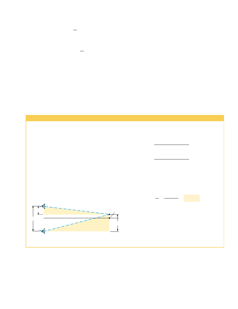
Example 18.1 Two Speakers Driven by the Same Source

3.00 m

8.00 m

r

2

r

1

O

0.350 m

1.85 m

P

1.15 m

Figure 18.6 (Example 18.1) Two speakers emit sound waves to

a listener at P.

18.2 Standing Waves

The sound waves from the speakers in Example 18.1 leave the speakers in the forward
direction, and we considered interference at a point in front of the speakers. Suppose
that we turn the speakers so that they face each other and then have them emit sound
of  the  same  frequency  and  amplitude.  In  this  situation,  two  identical  waves  travel  in

Figure  18.6  shows  the  physical  arrangement  of  the

speakers, along with two shaded right triangles that can be
drawn on the basis of the lengths described in the problem.
From these triangles, we find that the path lengths are

and

Hence, the path difference is r

2

#

r

1

"

0.13 m. Because we

require that this path difference be equal to '/2 for the first
minimum, we find that ' " 0.26 m.

To  obtain  the  oscillator  frequency,  we  use  Equation

16.12, " 'f, where is the speed of sound in air, 343 m/s:

What  If?

What  if  the  speakers  were  connected  out  of

phase? What happens at point P in Figure 18.6?

Answer In this situation, the path difference of '/2 com-
bines  with  a  phase  difference  of  '/2  due  to  the  incorrect
wiring to give a full phase difference of '. As a result, the
waves  are  in  phase  and  there  is  a  maximum intensity  at
point P.

1.3 kHz

"

v

'

"

343 m/s

0.26 m

"

r

2

"

(8.00 m)

2

!

(1.85 m)

2

"

8.21 m

r

1

"

(8.00 m)

2

!

(1.15 m)

2

"

8.08 m

A  pair  of  speakers  placed  3.00 m  apart  are  driven  by  the
same oscillator (Fig. 18.6). A listener is originally at point O,
which is located 8.00 m from the center of the line connect-
ing  the  two  speakers.  The  listener  then  walks  to  point  P,
which  is  a  perpendicular  distance  0.350 m  from  O,  before
reaching  the  first  minimum in  sound  intensity.  What  is  the
frequency of the oscillator?

Solution To  find  the  frequency,  we  must  know  the  wave-
length of the sound coming from the speakers. With this in-
formation,  combined  with  our  knowledge  of  the  speed  of
sound, we can calculate the frequency. The wavelength can
be determined from the interference information given. The
first  minimum  occurs  when  the  two  waves  reaching  the  lis-
tener at point are 180° out of phase—in other words, when
their path difference )equals '/2. To calculate the path dif-
ference, we must first find the path lengths r

1

and r

2

.

opposite directions in the same medium, as in Figure 18.7. These waves combine in ac-
cordance with the superposition principle.

We can analyze such a situation by considering wave functions for two transverse si-

nusoidal waves having the same amplitude, frequency, and wavelength but traveling in
opposite directions in the same medium:

y

1

"

sin(kx # $t)

y

2

"

sin(kx ! $t)

where y

1

represents a wave traveling in the ! direction and y

2

represents one traveling

in the # direction. Adding these two functions gives the resultant wave function y:

y

1

!

y

2

"

sin(kx # $t) ! sin(kx ! $t)

When  we  use  the  trigonometric  identity  sin(b) " sin(a)  cos(b) ( cos(a)  sin(b),
this expression reduces to

(18.3)

Equation 18.3 represents the wave function of a 

standing wave. A standing wave,

such as the one shown in Figure 18.8, is an oscillation pattern with a stationary outline
that results from the superposition of two identical waves traveling in opposite direc-
tions.

Notice that Equation 18.3 does not contain a function of kx # $t. Thus, it is not an

expression for a traveling wave. If we observe a standing wave, we have no sense of mo-
tion in the direction of propagation of either of the original waves. If we compare this
equation with Equation 15.6, we see that Equation 18.3 describes a special kind of sim-
ple harmonic motion. Every element of the medium oscillates in simple harmonic mo-
tion with the same frequency $ (according to the cos $

factor in the equation). How-

ever, the amplitude of the simple harmonic motion of a given element (given by the
factor 2sin kx, the coefficient of the cosine function) depends on the location of
the element in the medium.

The maximum amplitude of an element of the medium has a minimum value of

zero when satisfies the condition sin kx " 0, that is, when

kx " &, 2&, 3&, . . . 

Because " 2&/', these values for kx give

(18.4)

These points of zero amplitude are called 

nodes.

"

'
2

, ', 

3'

2

, * * * "

n'

2


" 0, 1, 2, 3, * * *

" (2A sin kx)


cos $t

550

C H A P T E R   18 •  Superposition and Standing Waves

v

v

Figure 18.7 Two speakers emit

sound waves toward each other.

When they overlap, identical waves

traveling in opposite directions will

combine to form standing waves.

Antinode

Antinode

Node

2A sin kx

Node

Figure 18.8 Multiflash photograph of a standing wave on a string. The time behavior

of the vertical displacement from equilibrium of an individual element of the string is

given by cos 

$

t. That is, each element vibrates at an angular frequency 

$

. The ampli-

tude of the vertical oscillation of any elements of the string depends on the horizontal

position of the element. Each element vibrates within the confines of the envelope

function 2sin kx

©

1991 Richard Megna/Fundamental Photographs

PITFALL PREVENTION

18.2 Three Types of

Amplitude

We  need  to  distinguish  carefully
here  between  the  amplitude  of
the  individual  waves, 
which  is  A,
and  the  amplitude  of  the  simple
harmonic motion of the elements
of the medium, 
which is 2sin kx.
A given  element  in  a  standing
wave  vibrates  within  the  con-
straints  of  the  envelope function 
2sin kx,  where  is  that  ele-
ment’s  position  in  the  medium.
This  is  in  contrast  to  traveling 
sinusoidal waves, in which all ele-
ments oscillate with the same am-
plitude  and  the  same  frequency,
and  the  amplitude  A  of  the  wave
is the same as the amplitude of
the  simple  harmonic  motion  of
the  elements.  Furthermore,  we
can identify the amplitude of the
standing wave 
as 2A.

The element with the greatest possible displacement from equilibrium has an ampli-

tude of 2A, and we define this as the amplitude of the standing wave. The positions in
the  medium  at  which  this  maximum  displacement  occurs  are  called 

antinodes. The

antinodes  are  located  at  positions  for  which  the  coordinate  satisfies  the  condition
sin kx " ( 1, that is, when

Thus, the positions of the antinodes are given by

(18.5)

In examining Equations 18.4 and 18.5, we note the following important features of

the locations of nodes and antinodes:

"

'
4

3'

4

5'

4

,  * * * "

n'

4


" 1, 3, 5,  * * *  

kx "

&

2

3&

2

5&

2

, * * *

S E C T I O N   18 . 2 •  Standing Waves

551

The distance between adjacent antinodes is equal to '/2.
The distance between adjacent nodes is equal to '/2.
The distance between a node and an adjacent antinode is '/4.

Wave  patterns  of  the  elements  of  the  medium  produced  at  various  times  by

two waves  traveling  in  opposite  directions  are  shown  in  Figure  18.9.  The  blue  and
green  curves  are  the  wave  patterns  for  the  individual  traveling  waves,  and  the  red
curves are the wave patterns for the resultant standing wave. At " 0 (Fig. 18.9a),
the two traveling waves are in phase, giving a wave pattern in which each element of
the  medium  is  experiencing  its  maximum  displacement  from  equilibrium.  One
quarter  of  a  period  later,  at  T/4  (Fig.  18.9b),  the  traveling  waves  have  moved
one  quarter  of  a  wavelength  (one  to  the  right  and  the  other  to  the  left).  At  this
time, the traveling waves are out of phase, and each element of the medium is pass-
ing  through  the  equilibrium  position  in  its  simple  harmonic  motion.  The  result  is
zero  displacement  for  elements  at  all  values  of  x—that  is,  the  wave  pattern  is  a
straight line. At T/2 (Fig. 18.9c), the traveling waves are again in phase, produc-
ing a wave pattern that is inverted relative to the " 0 pattern. In the standing wave,
the  elements  of  the  medium  alternate  in  time  between  the  extremes  shown  in
Figure 18.9a and c.

(a) t = 0

y

1

y

2

y

N

N

N N

N

A

A

(b) t T/4

y

2

y

1

y

(c) T/2

y

1

A

A

y

2

y

N

N N

N N

A

A

A

A

Active Figure 18.9 Standing-wave patterns produced at various times by two waves of

equal amplitude traveling in opposite directions. For the resultant wave y, the nodes

(N) are points of zero displacement, and the antinodes (A) are points of maximum dis-

placement.

At the Active Figures link

at http://www.pse6.com, you

can choose the wavelength of

the waves and see the standing

wave that results.

Position of antinodes

552

C H A P T E R   18 •  Superposition and Standing Waves

Quick Quiz 18.3

Consider a standing wave on a string as shown in Figure

18.9. Define the velocity of elements of the string as positive if they are moving upward
in the figure. At the moment the string has the shape shown by the red curve in Figure
18.9a,  the  instantaneous  velocity  of  elements  along  the  string  (a)  is  zero  for  all
elements (b) is positive for all elements (c) is negative for all elements (d) varies with
the position of the element.

Quick  Quiz  18.4

Continuing  with  the  scenario  in  Quick  Quiz  18.3,  at  the

moment the string has the shape shown by the red curve in Figure 18.9b, the instanta-
neous velocity of elements along the string (a) is zero for all elements (b) is positive for
all elements (c) is negative for all elements (d) varies with the position of the element.

Example 18.2 Formation of a Standing Wave

18.3 Standing Waves in a String

Fixed at Both Ends

Consider a string of length fixed at both ends, as shown in Figure 18.10. Standing
waves are set up in the string by a continuous superposition of waves incident on and
reflected from the ends. Note that there is a boundary condition for the waves on the

Two waves traveling in opposite directions produce a stand-
ing wave. The individual wave functions are

y

1

"

(4.0 cm) sin(3.0# 2.0t

y

2

"

(4.0 cm) sin(3.0! 2.0t)

where and are measured in centimeters.

(A)

Find  the  amplitude  of  the  simple  harmonic  motion  of

the element of the medium located at " 2.3 cm.

Solution The standing wave is described by Equation 18.3;
in  this  problem,  we  have  " 4.0 cm,  " 3.0 rad/cm,  and
$ "

2.0 rad/s. Thus,

" (2sin kx) cos $" [(8.0 cm)sin 3.0x] cos 2.0t

Thus, we obtain the amplitude of the simple harmonic mo-
tion of the element at the position " 2.3 cm by evaluating
the coefficient of the cosine function at this position:

(B)

Find  the  positions  of  the  nodes  and  antinodes  if  one

end of the string is at " 0.

Solution With  " 2&/' " 3.0 rad/cm,  we  see  that  the
wavelength  is  ' " (2&/3.0) cm.  Therefore,  from  Equation
18.4 we find that the nodes are located at

0, 1, 2, 3, . . .

n  

'
2

"

n 


!

&

3

"

 cm


"

4.6 cm

"

(8.0 cm) sin (6.9 rad) "

y


max

"

(8.0 cm)sin 3.0x

#

x"2.3

and  from  Equation  18.5  we  find  that  the  antinodes  are  lo-
cated at

(C)

What  is  the  maximum  value  of  the  position  in  the

simple  harmonic  motion  of  an  element  located  at  an
antinode?

Solution According  to  Equation  18.3,  the  maximum  posi-
tion  of  an  element  at  an  antinode  is  the  amplitude  of  the
standing wave, which is twice the amplitude of the individual
traveling waves:

y

max

"

2A(sin kx)

max

"

2(4.0 cm)(( 1) "

where  we  have  used  the  fact  that  the  maximum  value  of
sin kx is ( 1. Let us check this result by evaluating the coeffi-
cient  of  our  standing-wave  function  at  the  positions  we
found for the antinodes:

In  evaluating  this  expression,  we  have  used  the  fact  that  n
is an  odd  integer;  thus,  the  sine  function  is  equal  to  ( 1,
depending on the value of n.

 " (8.0 cm) sin 

$

n


!

&

2

"

 rad

%

" (

8.0 cm

 " (8.0 cm) sin 

$

3.0n


!

&

6

"

 rad

%

y


max 

"

(8.0 cm)sin 3.0x

#

x"n(&/6)

(

8.0 cm

1, 3, 5, . . .

n 


'
4

"

n 


!

&

6

"

 cm


"


Content   ..  136  137  138  139   ..