Kawasaki Motorcycle Ninja ZX-6R / Ninja ZX-6R ABS. Service Manual (2013 year) - page 22
 

  Index      Manuals     Kawasaki Motorcycle Ninja ZX-6R / Ninja ZX-6R ABS. Service Manual (2013 year)


Search            copyright infringement  


Content      ..     20      21      22      23     ..


Kawasaki Motorcycle Ninja ZX-6R / Ninja ZX-6R ABS. Service Manual (2013 year) - page 22


SELF-DIAGNOSIS SYSTEM 17-73

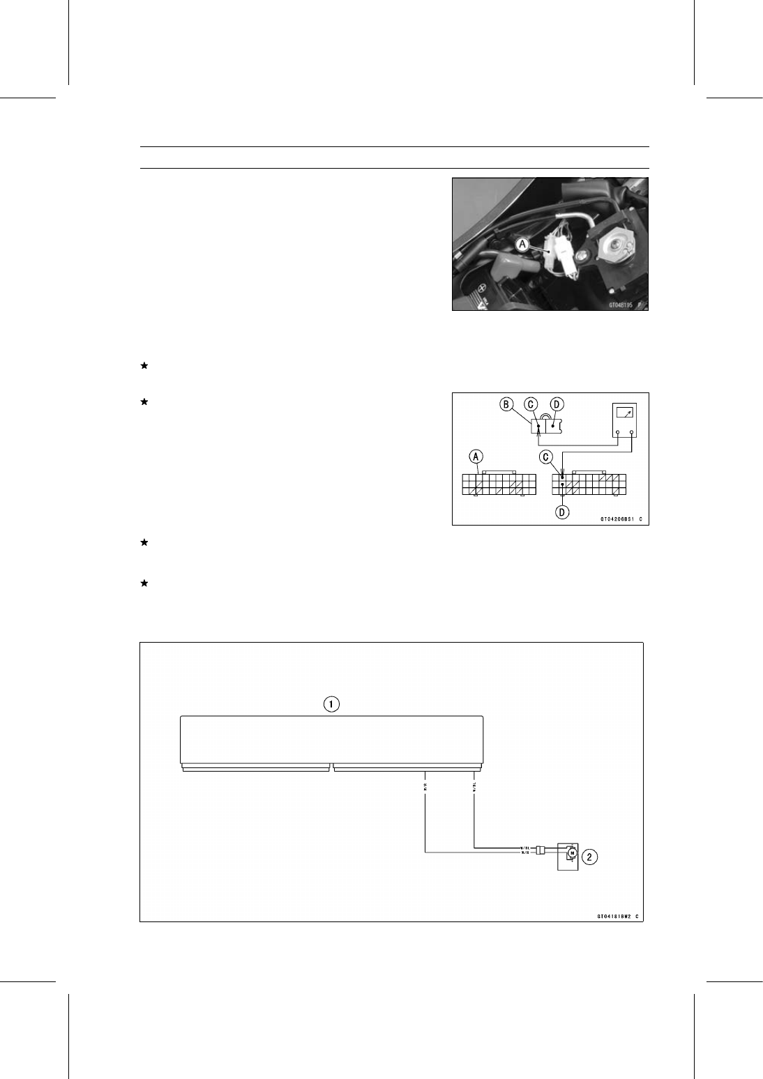
Exhaust Butterfly Valve Actuator (Service Code 63)

Exhaust Butterfly Valve Actuator Resistance
Inspection

Turn the ignition switch off.

Disconnect the exhaust butterfly valve actuator lead con-
nector (2 pins connector) [A].

Set the hand tester to the × 1

range and connect it to

the exhaust butterfly valve actuator connector.

Special Tool - Hand Tester: 57001-1394

Measure the exhaust butterfly valve actuator resistance.

Exhaust Butterfly Valve Actuator Resistance

Connections:

P lead

←→

GY lead

Standard:

5

200

(for reference)

If the reading is 0 or infinity (

)

, replace the exhaust

butterfly valve actuator.

If the reading is in specification, remove the ECU and
check the wiring for continuity between main harness con-
nectors.

Disconnect the ECU and actuator connectors.

Wiring Inspection

ECU Connector [A]

←→

Exhaust Butterfly Valve Actuator Connector [B]

W/BL lead (ECU terminal 2) [C]

W/R lead (ECU terminal 13) [D]

If the wiring is good, check the ECU for its ground and
power supply (see ECU Power Supply Inspection in the
Fuel System (DFI) chapter).
If the ground and power supply are good, replace the ECU
(see ECU Removal/Installation in the Fuel System (DFI)
chapter).

Exhaust Butterfly Valve Actuator Circuit

1. ECU
2. Exhaust Butterfly Valve Actuator

17-74 SELF-DIAGNOSIS SYSTEM

Air Switching Valve (Service Code 64)

Air Switching Valve Removal/Installation

Refer to the Air Switching Valve Removal/Installation in
the Engine Top End chapter.

Air Switching Valve Inspection

Refer to the Air Switching Valve Unit Test in the Electrical
System chapter.
If the air switching valve [A] is normal, check the wiring
for continuity (see Air Switching Valve Circuit).

Special Tool - Hand Tester: 57001-1394

If the wiring is good, check the ECU for its ground and
power supply (see ECU Power Supply Inspection in the
Fuel System (DFI) chapter).
If the ground and power supply are good, replace the ECU
(see ECU Removal/Installation in the Fuel System (DFI)
chapter).

Air Switching Valve Circuit

1. Ignition Switch
2. Air Switching Valve
3. Joint Connector D
4. ECU
5. Frame Ground 3
6. Engine Ground
7. Battery 12 V 8 Ah
8. Starter Relay

9. Main Fuse 30 A

10. ECU Fuse 15 A

11. Frame Ground 1

12. Relay Box
13. ECU Main Relay
14. Fuse Box 1
15. Ignition Fuse 15 A
16. Joint Connector E

SELF-DIAGNOSIS SYSTEM 17-75

Oxygen Sensor Heater (Service Code 67, Equipped Models)

Oxygen Sensor Heater Removal/Installation

The oxygen sensor heater is built in the oxygen sensor.

So, the heater itself can not be removed. Remove the oxy-
gen sensor (see Oxygen Sensor Removal (Equipped Mod-
els) in the Electrical System chapter).

Oxygen Sensor Heater Resistance Inspection

Turn the ignition switch off.

Remove the fuel tank (see Fuel Tank Removal in the Fuel
System (DFI) chapter).

Disconnect the oxygen sensor lead connector [A].

Connect a digital meter [A] to the terminals in the oxygen
sensor lead connector [B].

Measure the oxygen sensor heater resistance.

Oxygen Sensor Heater Resistance

Connections: W lead [C]

←→

W lead [D]

Standard: 6.7

10.5

at 20° (68°F)

If the reading is out of the standard, replace the sensor.
If the reading is within the standard, check the power
source voltage (see Oxygen Sensor Heater Power
Source Voltage Inspection).

17-76 SELF-DIAGNOSIS SYSTEM

Oxygen Sensor Heater (Service Code 67, Equipped Models)

Oxygen Sensor Heater Power Source Voltage
Inspection

NOTE

Be sure the battery is fully charged.

Turn the ignition switch off.

Remove the fuel tank (see Fuel Tank Removal in the Fuel
System (DFI) chapter).

Disconnect the oxygen sensor lead connector and con-
nect the measuring adapter [A] between these connec-
tors as shown.

Main Harness [B]
Oxygen Sensor [C]

Special Tool - Measuring Adapter: 57001-1700

Connect a digital meter [D] to the measuring adapter lead.

Oxygen Sensor Heater Power Source Voltage

Connections to Adapter:

Digital Meter (+)

R (main harness BR/W) lead

Digital Meter (–)

Frame Ground terminal

Measure the power source voltage with the engine
stopped and with the connector joined.

Turn the ignition switch on

Power Source Voltage

Standard: Battery Voltage

Turn the ignition switch off.
If the reading is in specification, but the problem still ex-
ists, replace the ECU (see ECU Removal/Installation in
the Fuel System (DFI) chapter).
If the reading is out of the standard, check the following.

ECU Fuse 15 A (see Fuse Inspection in the Electrical
System chapter)
Power Source Wiring (see Oxygen Sensor Circuit)

If the fuse and wiring are good, remove the ECU and
check the wiring for continuity between harness connec-
tors.

Special Tool - Hand Tester: 57001-1394

Disconnect the ECU and sensor connectors.

Wiring Continuity Inspection

ECU Connector [A]

←→

Oxygen Sensor Connectors [B]

P/BK lead (ECU terminal 51) [C]

If the wiring is good, check the ECU for its ground and
power supply (see ECU Power Supply Inspection in the
Fuel System (DFI) chapter).
If the ground and power supply are good, replace the ECU
(see ECU Removal/Installation in the Fuel System (DFI)
chapter).

SELF-DIAGNOSIS SYSTEM 17-77

Oxygen Sensor Heater (Service Code 67, Equipped Models)

Oxygen Sensor Circuit

1. ECU
2. Frame Ground 3
3. Engine Ground
4. Battery 12 V 8 Ah
5. Starter Relay
6. Main Fuse 30 A
7. ECU Fuse 15 A
8. Relay Box
9. ECU Main Relay

10. Fuse Box 1

11. Ignition Fuse 15 A

12. Joint Connector E
13. Ignition Switch
14. Water-proof Joint 2
15. Oxygen Sensor

17-78 SELF-DIAGNOSIS SYSTEM

Oxygen Sensor - Incorrect Output Voltage (Service Code 94 (Equipped Models))

Oxygen Sensor Removal/Installation

Refer

to

the

Oxygen

Sensor

Removal/Installation

(Equipped Models) in the Electrical System chapter.

Oxygen Sensor Inspection

Warm up the engine thoroughly until the radiator fan
starts.

Turn the ignition switch off.

Remove:

Fuel Tank (see Fuel Tank Removal in the Fuel System
(DFI) chapter)

Disconnect:

Oxygen Sensor Lead Connector [A]

Connect the measuring adapter [A] between the main
harness connector and oxygen sensor lead connector as
shown.

Main Harness [B]
Oxygen Sensor [C]

Special Tool - Measuring Adapter: 57001-1700

Connect a digital meter [D] to the measuring adapter
leads.

Oxygen Sensor Output Voltage

Connections to Adapter:

Digital Meter (+)

R (sensor BK) lead

Digital Meter (

)

BK (sensor GY) lead

Remove the air switching valve [A] (see Air Switching
Valve Removal in the Engine Top End chapter).

Do not disconnect the air switching valve connector [B].

SELF-DIAGNOSIS SYSTEM 17-79

Oxygen Sensor - Incorrect Output Voltage (Service Code 94 (Equipped Models))

Install the suitable plugs [A] on the fitting of the air suction
valve covers, and shut off the secondary air.

Connect the following parts temporarily.

Fuel Pump Lead Connector [A]
Extension Tube [B]
Air Cleaner Housing (see Air Cleaner Housing Installa-
tion)

Special Tool - Extension Tube: 57001-1578

Start the engine, and let it idle.

Measure the output voltage with the connector joined.

Output Voltage (with Plugs)

Standard:

DC 0.8 V or more

Next, remove the plugs from the fittings [A] with idling.

Measure the output voltage with the connector joined.

Output Voltage (without Plugs)

Standard:

DC 0.24 V or less

Turn the ignition switch off.
If the reading is out of the standard (with plugs: DC 0.8
V or more, without plugs: DC 0.24 V or less), check the
following.

Fuel Pressure (see Fuel Pressure Inspection in the Fuel
System (DFI) chapter)
Fuel Injector (see Fuel Injector section)

If the fuel pressure and fuel injectors are good, replace
the sensor.
If the reading is within the standard (with plugs: DC 0.8
V or more, without plugs: DC 0.24 V or less), check the
ECU for its ground and power supply (see ECU Power
Supply Inspection in the Fuel System (DFI) chapter).
If the ground and power supply are good, replace the ECU
(see ECU Removal/Installation in the Fuel System (DFI)
chapter).

17-80 SELF-DIAGNOSIS SYSTEM

Oxygen Sensor - Incorrect Output Voltage (Service Code 94 (Equipped Models))

Oxygen Sensor Circuit

1. ECU
2. Frame Ground 3
3. Engine Ground
4. Battery 12 V 8 Ah
5. Starter Relay
6. Main Fuse 30 A
7. ECU Fuse 15 A
8. Relay Box
9. ECU Main Relay

10. Fuse Box 1

11. Ignition Fuse 15 A

12. Joint Connector E
13. Ignition Switch
14. Water-proof Joint 2
15. Oxygen Sensor

SELF-DIAGNOSIS SYSTEM 17-81

KIBS Hydraulic Unit Communication Error (Service Code 1b, KIBS Equipped
Models)

KIBS Hydraulic Unit Communication Line
Inspection

When the data (for status of KIBS hydraulic unit) is not
sent from the KIBS hydraulic unit to the meter unit and
ECU, the service code 1b is displayed.

The data is sent through the CAN communication line.

The service code 1b is detected with the meter unit.

The FI symbol does not appear in this error code.

When the service code 1b [A] is detected, the yellow ABS
indicator light (LED) [B] goes on and the code of 1b dis-
played on the LCD.

Check the wiring for continuity between main harness
connector.

Disconnect:

KIBS Hydraulic Unit Connector (see KIBS Hydraulic Unit
Removal in the Brakes chapter)
Meter Unit Connector (see Meter Unit Removal in the
Electrical System chapter)

Special Tool - Hand Tester: 57001-1394

Wiring Inspection

KIBS Hydraulic Unit Connector [A]

←→

Meter Unit Connector [B]

GY/BL lead (KIBS Hydraulic Unit terminal 2) [C]

LB lead (KIBS Hydraulic Unit terminal 11) [D]

If the wiring is good, replace the KIBS hydraulic unit (see
KIBS Hydraulic Unit Removal/Installation in the Brakes
chapter).

17-82 SELF-DIAGNOSIS SYSTEM

KIBS Hydraulic Unit Communication Error (Service Code 1b, KIBS Equipped
Models)

KIBS Hydraulic Unit Communication Line Circuit

1. ECU
2. KIBS Hydraulic Unit
3. Meter Unit
4. Yellow ABS Indicator Light (LED)

SELF-DIAGNOSIS SYSTEM 17-83

Purge Valve (Service Code 3A) (CAL Model)

Purge Valve Removal/Installation

Remove:

Right Fairing Cover (see Fairing Cover Removal in the
Frame chapter)
Right Side Cover (see Side Cover Removal in the Frame
chapter)
Bolt [A] and Washer

Disconnect the connector [A].

Remove the nut [B].

Disconnect the tubes [A].

Remove the purge valve [B].

Installation is the reverse of removal.

Run the tubes correctly (see Cable, Wire, and Hose Rout-
ing section in the Appendix chapter).

Purge Valve Inspection

Remove the purge valve (see Purge Valve Removal/In-
stallation).

Set the hand tester [A] to the × 1

range and connect it

to the purge valve terminals as shown.

Special Tool - Hand Tester: 57001-1394

Purge Valve Resistance

Standard:

30

34

at 20°C (68°F)

If the resistance reading is out of the specified value, re-
place it with a new one.

17-84 SELF-DIAGNOSIS SYSTEM

Purge Valve (Service Code 3A) (CAL Model)

Connect the 12 V battery [A] to the purge valve terminals
as shown.

Blow the air to the intake air duct [A], and make sure that
the air flows from the outlet air duct [B].

Disconnect the 12 V battery.

Blow the air to the intake air duct [A] again, and make sure
that the air does not flow from the outlet air duct [B].
If the purge valve dose not operate as described, replace
it with a new one.

SELF-DIAGNOSIS SYSTEM 17-85

Purge Valve (Service Code 3A) (CAL Model)

Purge Valve Circuit

1. ECU
2. Frame Ground 3
3. Engine Ground
4. Battery 12 V 8 Ah
5. Starter Relay
6. Main Fuse 30 A
7. ECU Fuse 15 A
8. Relay Box
9. ECU Main Relay

10. Fuse Box 1

11. Ignition Fuse 15 A

12. Joint Connector E
13. Ignition Switch
14. Purge Valve

17-86 SELF-DIAGNOSIS SYSTEM

KIBS Service Codes (KIBS Equipped Models)

Solenoid Valve Inspection (Service Code b 13, b
14, b 17, b 18)

The solenoid valve is built in the KIBS Hydraulic Unit [A].
Therefore the solenoid valve cannot be checked directly.

Perform the Pre-Diagnosis Inspection 1 and 2 (see In-
quiries to Rider in the Brakes chapter).
If any of these service codes appears even if all checks
are ended, replace the KIBS hydraulic unit.
If the service code does not appear, the KIBS system nor-
mal (temporary failure).

KIBS Solenoid Valve Relay Inspection (Service
Code b 19)

The KIBS solenoid valve relay is built in the KIBS Hy-
draulic Unit. Therefore the relay cannot be checked di-
rectly.

Perform the Pre-Diagnosis Inspection 1 and 2 (see In-
quiries to Rider in the Brakes chapter).
If this service code appears even if all checks are ended,
replace the KIBS hydraulic unit.
If the service code does not appear, the KIBS system nor-
mal (temporary failure).

Front, Rear Wheel Rotation Difference Abnormal
Inspection (Service Code b 25)

Check the following and correct the faulty part.

Incorrect Tire Pressure
Tires not recommended for the motorcycle were installed
(incorrect tire size).
Deformation of Wheel or Tire
Missing Teeth or Clogging with Foreign Matter of Sensor
Rotor (see Wheel Rotation Sensor Rotor Inspection in
the Brakes chapter)

If the all parts corrected, go to next step.

Perform the Pre-Diagnosis Inspection 1 and 2 (see In-
quiries to Rider in the Brakes chapter).
If this service code appears even if all checks are ended,
replace the KIBS hydraulic unit.
If the service code does not appear, the KIBS system nor-
mal (temporary failure).

KIBS Motor Relay Inspection (Service Code b 35)

Check the KIBS motor relay fuse (25 A) [A] (see Fuse
Inspection in the Electrical System chapter)
If the fuse is good, check the wiring continuity as follows.

Disconnect:

Battery Positive Cable (see Battery Removal in the Elec-
trical System chapter)
KIBS Hydraulic Unit Lead Connector (see KIBS Hy-
draulic Unit Removal in the Brakes chapter)

SELF-DIAGNOSIS SYSTEM 17-87

KIBS Service Codes (KIBS Equipped Models)

Check the wiring continuity between the positive cable
terminal [A] of the battery and R/W lead terminal [B] in
the KIBS Hydraulic Unit Lead Connector [C].
If the wiring is open, replace or repair the harness (see
KIBS System Circuit in the Brakes chapter).
If the wiring is good, go to next step.

The KIBS motor relay is built in the KIBS Hydraulic Unit.
Therefore the relay cannot be checked directly.

Perform the Pre-Diagnosis Inspection 1 and 2 (see In-
quiries to Rider in the Brakes chapter).
If this service code appears even if all checks are ended,
replace the KIBS hydraulic unit.
If the service code does not appear, the KIBS system nor-
mal (temporary failure).

Front Wheel Rotation Sensor Signal Abnormal
(Service Code b 42)

Measure the air gap between the front wheel rotation sen-
sor and sensor rotor.

Thickness Gauge [A]

Air Gap

Standard:

0.4

1.6 mm (0.02

0.06 in.)

If the measurement is not the standard, check each part
for deformation and looseness and correct accordingly.
If the measurement is the standard, go to next step.

Check that there is iron or other magnetic deposits be-
tween the sensor and sensor rotor, and the sensor rotor
slots for obstructions.

Check the installation condition of the sensor for loose-
ness.

Check the sensor and sensor rotor tip for deformation or
damage (e.g., chipped sensor rotor teeth).
If the sensor and sensor rotor in bad condition, remove
the any deposits. Install the proper part or replace faulty
part.
If the all items are good, go to next step.

Perform the Pre-Diagnosis Inspection 1 and 2 (see In-
quiries to Rider in the Brakes chapter).
If this service code appears even if all checks are ended,
replace the KIBS hydraulic unit.
If the service code does not appear, the KIBS system nor-
mal (temporary failure).

17-88 SELF-DIAGNOSIS SYSTEM

KIBS Service Codes (KIBS Equipped Models)

Front Wheel Rotation Sensor Wiring Inspection
(Service Code b 43)

Disconnect the front wheel rotation sensor lead connec-
tor [A] (see Front Wheel Rotation Sensor Removal in the
Brakes chapter).

Disconnect the KIBS hydraulic unit lead connector (see
KIBS Hydraulic Unit Removal in the Brakes chapter).

Check the wiring continuity of the W lead and Y lead.

Front Wheel Rotation Sensor Lead Connector [A]
KIBS Hydraulic Unit Lead Connector [B]
W Lead Terminals [C]
Y Lead terminals [D]

If the wiring is open, replace or repair the harness (see
KIBS System Circuit in the Brakes chapter).
If the wiring is good, go to next step.

Perform the Pre-Diagnosis Inspection 1 and 2 (see In-
quiries to Rider in the Brakes chapter).
If this service code appears even if all checks are ended,
replace the front wheel rotation sensor (see Front Wheel
Rotation Sensor Removal in the Brakes chapter).

Still, when it is not good, replace the KIBS hydraulic unit.
If the service code does not appear, the KIBS system nor-
mal (temporary failure).

Rear Wheel Rotation Sensor Signal Abnormal
(Service Code b 44)

Measure the air gap between the rear wheel rotation sen-
sor and sensor rotor.

Thickness Gauge [A]

Air Gap

Standard:

0.4

1.6 mm (0.02

0.06 in.)

If the measurement is not the standard, check each part
for deformation and looseness and correct accordingly.
If the measurement is the standard, go to next step.

Check that there is iron or other magnetic deposits be-
tween the sensor and sensor rotor, and the sensor rotor
slots for obstructions.

Check the installation condition of the sensor for loose-
ness.

Check the sensor and sensor rotor tip for deformation or
damage (e.g., chipped sensor rotor teeth).
If the sensor and sensor rotor in bad condition, remove
the any deposits. Install the proper part or replace faulty
part.
If the all items are good, go to next step.

SELF-DIAGNOSIS SYSTEM 17-89

KIBS Service Codes (KIBS Equipped Models)

Perform the Pre-Diagnosis Inspection 1 and 2 (see In-
quiries to Rider in the Brakes chapter).
If this service code appears even if all checks are ended,
replace the KIBS hydraulic unit.
If the service code does not appear, the KIBS system nor-
mal (temporary failure).

Rear Wheel Rotation Sensor Wiring Inspection
(Service Code b 45)

Disconnect the rear wheel rotation sensor lead connec-
tor [A] (see Rear Wheel Rotation Sensor Removal in the
Brakes chapter).

Disconnect the KIBS hydraulic unit lead connector (see
KIBS Hydraulic Unit Removal in the Brakes chapter).

Check the wiring continuity of the G lead and R lead.

Rear Wheel Rotation Sensor Lead Connector [A]
KIBS Hydraulic Unit Lead Connector [B]
G Lead Terminals [C]
R Lead terminals [D]

If the wiring is open, replace or repair the harness (see
KIBS System Circuit in the Brakes chapter).
If the wiring is good, go to next step.

Perform the Pre-Diagnosis Inspection 1 and 2 (see In-
quiries to Rider in the Brakes chapter).
If this service code appears even if all checks are ended,
replace the rear wheel rotation sensor (see Rear Wheel
Rotation Sensor Removal in the Brakes chapter).

Still, when it is not good, replace the KIBS hydraulic unit.
If the service code does not appear, the KIBS system nor-
mal (temporary failure).

Power Supply Voltage Inspection (Low-Voltage)
(Service Code b 52)

Check the battery condition (see Charging Condition In-
spection in the Electrical System chapter).
If the battery is good condition, perform the Pre-Diagnosis
Inspection 1 and 2 (see Inquiries to Rider in the Brakes
chapter).
If this service code appears even if all checks are ended,
replace the KIBS hydraulic unit.
If the service code does not appear, the KIBS system nor-
mal (temporary failure).

17-90 SELF-DIAGNOSIS SYSTEM

KIBS Service Codes (KIBS Equipped Models)

Power Supply Voltage Inspection (Over-Voltage)
(Service Code b 53)

Check the charging voltage (see Charging Voltage In-
spection in the Electrical System chapter).
If the charging voltage is good, perform the Pre-Diagnosis
Inspection 1 and 2 (see Inquiries to Rider in the Brakes
chapter).
If this service code appears even if all checks are ended,
replace the KIBS hydraulic unit.
If the service code does not appear, the KIBS system nor-
mal (temporary failure).

ECU Inspection (Service Code b 55)

This ECU is built in the KIBS Hydraulic Unit. Therefore
the ECU cannot be checked directly.

Perform the Pre-Diagnosis Inspection 1 and 2 (see In-
quiries to Rider in the Brakes chapter).
If this service code appears even if all checks are ended,
replace the KIBS hydraulic unit.
If the service code does not appear, the KIBS system nor-
mal (temporary failure).

CAN Communication (Transmission)/CAN
Bus OFF Monitor Inspection
(Service Code b 57)
CAN Communication (Reception)
Monitor Inspection (Service Code b 58)

Disconnect the KIBS hydraulic unit lead connector (see
KIBS Hydraulic Unit Removal in the Brakes chapter).

Measure the CAN communication line resistance.

KIBS Hydraulic Unit Lead Connector [A]
GY/BL Lead Terminal [B]
LB Lead Terminal [C]

Special Tool - Hand Tester: 57001-1394

CAN Communication Line Resistance

Standard:

30

70

If the reading is out of the standard, go to Check 1.
If the reading is the standard, go to Check 2.

Check 1

Check the CAN communication line resistance of follow-
ing parts.

Meter Unit (see Meter Unit Inspection in the Electrical
System chapter)
ECU (see CAN Communication Line Resistance Inspec-
tion in the Fuel System (DFI) chapter)

SELF-DIAGNOSIS SYSTEM 17-91

KIBS Service Codes (KIBS Equipped Models)

Check 2

Measure the resistance between the GY/BL [A] or LB [B]
terminal and ground [C].

KIBS Hydraulic Unit Lead Connector [D]

Special Tool - Hand Tester: 57001-1394

CAN Communication Line/Ground Resistance

Standard:

5

30 k

If the reading is out of the standard, replace or repair the
main harness.
If the reading is the standard, go to next step.

Perform the Pre-Diagnosis Inspection 1 and 2 (see In-
quiries to Rider in the Brakes chapter).
If this service code appears even if all checks are ended,
replace the KIBS hydraulic unit.
If the service code does not appear, the KIBS system nor-
mal (temporary failure).

Output Fluid Pressure Sensor (Front Brake)
Wiring Inspection (Service Code b 83)

The Output Fluid Pressure Sensor is built in the KIBS Hy-
draulic Unit. Therefore the sensor cannot be checked di-
rectly.

Perform the Pre-Diagnosis Inspection 1 and 2 (see In-
quiries to Rider in the Brakes chapter).
If this service code appears even if all checks are ended,
replace the KIBS hydraulic unit.

Output Fluid Pressure Sensor (Front Brake) Offset
Abnormal (Service Code b 84)

The Output Fluid Pressure Sensor is built in the KIBS Hy-
draulic Unit. Therefore the sensor cannot be checked di-
rectly.

Perform the Pre-Diagnosis Inspection 1 and 2 (see In-
quiries to Rider in the Brakes chapter).
If this service code appears even if all checks are ended,
replace the KIBS hydraulic unit.
If the service code does not appear, the KIBS system nor-
mal (temporary failure).

Fluid Pressure Sensor Supply Voltage Inspection
(Service Code b 89)

The Fluid Pressure Sensors are built in the KIBS Hy-
draulic Unit. Therefore the voltage cannot be checked
directly.

Perform the Pre-Diagnosis Inspection 1 and 2 (see In-
quiries to Rider in the Brakes chapter).
If this service code appears even if all checks are ended,
replace the KIBS hydraulic unit.
If the service code does not appear, the KIBS system nor-
mal (temporary failure).

APPENDIX 18-1

18

Appendix

Table of Contents

Cable, Wire, and Hose Routing ..............................................................................................

18-2

Troubleshooting Guide ...........................................................................................................

18-47

18-2 APPENDIX

Cable, Wire, and Hose Routing

APPENDIX 18-3

Cable, Wire, and Hose Routing

1. Immobilizer Amplifier Connector (Equipped Models)
2. Run the right switch housing lead to the inside of the front fork. Run the right switch housing

lead to the upside of the steering stem.

3. Cover the right turn signal light lead connector, headlight lead connector and city light lead con-

nector with the rubber cover.

4. Run the meter lead and immobilizer amplifier lead (equipped models) to the upside of the rib of

the air intake duct.

5. Run the left switch housing lead to the inside of the front fork. Run the left switch housing lead

to the upside of the steering stem.

6. Hold the harness at the white tape position of the harness to the hook of the air intake duct.
7. Cover the left turn signal light lead connector, headlight lead connector and city light lead con-

nector with the rubber cover.

8. Hold the harness with the clamp, and insert the projections of the clamp into the inner fairing.
9. Install the pad so that there is no space between the pad and bracket.

10. Hold the meter lead with the clamp, and install the clamp to the air intake duct.

11. Run the main harness to the outside of the front fork.

12. Check that the main harness does not swing.

18-4 APPENDIX

Cable, Wire, and Hose Routing

APPENDIX 18-5

Cable, Wire, and Hose Routing

1. Clutch Cable
2. Throttle Cable (Accelerator)
3. Throttle Cable (Decelerator)
4. Run the throttle cables between the steering stem head and clutch cable.
5. Align the white character on the accelerator cable with the clamp.
6. Align the clutch cable with the tab on the fuel tank bracket.
7. Clamp (Hold the clutch cable at the blue tape position.)
8. Clamp (Hold the throttle cables.)
9. Run the brake pipes between the frame and air cleaner housing (KIBS equipped models).

10. Run the throttle cables between the frame and air cleaner housing.

11. Run the clutch cable under the throttle cables.

12. Run the brake hose to the inside of the right switch housing lead. Run the brake hose to the

upside of the steering stem.

13. Run the right switch housing lead to the outside of the brake pipes (KIBS equipped models).
14. Clamp (Hold the right switch housing lead and front wheel rotation sensor lead.)

18-6 APPENDIX

Cable, Wire, and Hose Routing

1. Regulator/Rectifier Connectors
2. Clamp (Hold the alternator lead.)
3. Run the alternator lead through the clamp of the bracket.
4. Fuse Box
5. Hold the main harness with the clamp, and insert the projection of the clamp into the inner fairing.
6. Inside of Left Fame
7. Hold the main harness with the clamp, and insert the projection of the clamp into the frame.
8. Hold the main harness with the clamp, and insert the projection of the clamp into the bracket.

APPENDIX 18-7

Cable, Wire, and Hose Routing

1. Clamp (Hold the city light lead and head light lead.)
2. Clamp (Hold the right turn signal light lead, and face the open side of the clamp to the outside.

Hold the left side lead in the same way.)

3. Hold the harness with the clamp, and insert the projections of the clamp into the inner fairing.
4. Shove the rubber cover under the headlight.
5. Run the main harness under the regulator/rectifier bracket.
6. Hone Lead

18-8 APPENDIX

Cable, Wire, and Hose Routing

APPENDIX 18-9

Cable, Wire, and Hose Routing

1. Clamp (Hold the left switch housing lead, immobilizer antenna lead (equipped models) and ig-

nition switch lead, and face the open side of the clamp to the left side.)

2. Cover the left switch housing lead connector, immobilizer antenna lead connector (equipped

modes) and ignition switch lead connector with the rubber cover.

3. Clamp (Hold the right switch housing lead, radiator fan lead and front wheel rotation sensor

lead, and face the open side of the clamp to the left side.)

4. Cover the right switch housing lead connector, radiator fan lead connector and front wheel ro-

tation sensor lead connector with the rubber cover.

5. Air Switching Valve Connector
6. Stick Coil Connectors
7. Intake Air Temperature Sensor Lead
8. Intake Air Pressure Sensor #1 Connector
9. Subthrottle Valve Actuator Connector

10. Intake Air Pressure Sensor #2 Connector

11. Intake Air Temperature Sensor Connector

12. Clamp (Hold the intake air temperature sensor lead.)

18-10 APPENDIX

Cable, Wire, and Hose Routing

APPENDIX 18-11

Cable, Wire, and Hose Routing

1. Run the fuel injector lead under the fuel injector #1. Run the fuel injector lead to the upside of

the fuel injector #2.

2. Clamps (Hold the delivery pipe and fuel injector lead at the white tape position of the fuel injector

lead, and face the open side of the clamp downward.)

3. Fuel Injector Lead
4. Face the clamp to the backward.
5. Run the breather hose to the upside of the main harness.
6. Cover the frame ground terminal with the heat insulation rubber plate.
7. Fuel Injector Connectors
8. Do not pinch the main harness at the left side of the throttle body assy.
9. Throttle Position Sensor Connector

10. Oxygen Sensor lead Connector (Equipped Models)

11. Insert the fuel pipe into the pad. Install the pad to the upside of the oxygen sensor connector

(equipped models) and crankshaft sensor connector.

12. Crankshaft Senor Connector
13. Run the battery positive lead connector to the upside of the other leads and hoses.
14. Water Temperature Sensor Connector
15. Run the gear position sensor lead into the slit of the heat insulation rubber plate.

18-12 APPENDIX

Cable, Wire, and Hose Routing


Content      ..     20      21      22      23     ..