Kawasaki Motorcycle Ninja ZX-6R / Ninja ZX-6R ABS. Service Manual (2013 year) - page 21
 

  Index      Manuals     Kawasaki Motorcycle Ninja ZX-6R / Ninja ZX-6R ABS. Service Manual (2013 year)


Search            copyright infringement  


Content      ..     19      20      21      22     ..


Kawasaki Motorcycle Ninja ZX-6R / Ninja ZX-6R ABS. Service Manual (2013 year) - page 21


SELF-DIAGNOSIS SYSTEM 17-41

Gear Position Switch (Service Code 25)

Turn the ignition switch off.
If the reading is out of the standard, check the wiring for
continuity, using the wiring diagram in this section.

Special Tool - Hand Tester: 57001-1394

If the wiring is good, check the ECU for its ground and
power supply (see ECU Power Supply Inspection in the
Fuel System (DFI) chapter).
If the ground and power supply are good, replace the ECU
(see ECU Removal/Installation in the Fuel System (DFI)
chapter).

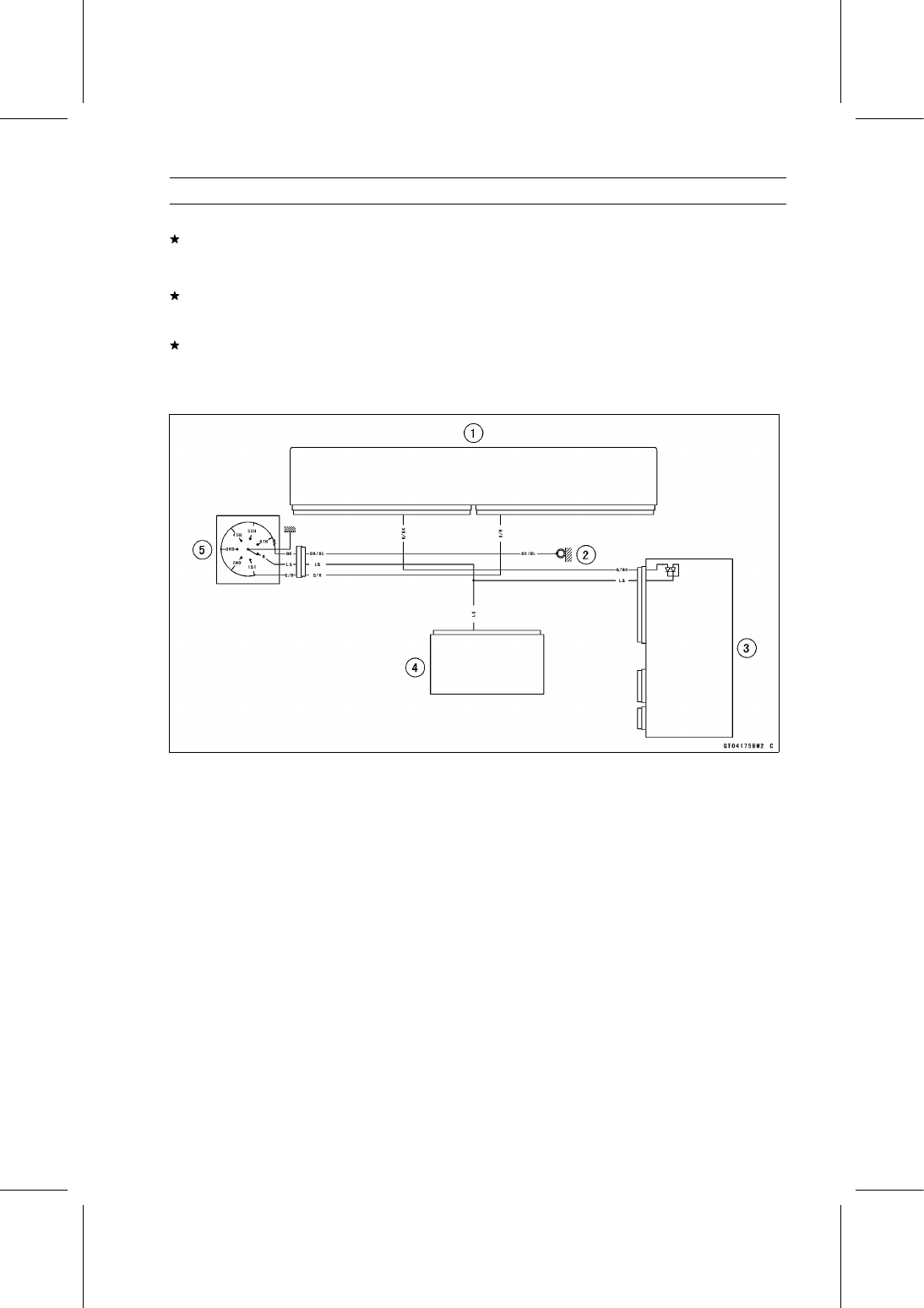
Gear Position Switch Circuit

1. ECU
2. Frame Ground 1
3. Relay Box
4. Meter Unit
5. Gear Position Switch

17-42 SELF-DIAGNOSIS SYSTEM

Front Wheel Rotation Sensor Signal (Service Code 27)

Front Wheel Rotation Sensor Signal Inspection

The front wheel rotation sensor sends the signal to the
ECU through the KIBS hydraulic unit (KIBS equipped
models).

For other than KIBS equipped models, the

signal is sent directly to the ECU.

The ECU uses the wheel rotation sensor signal for KTRC
control.

The service code 27 is detected with the ECU.

Inspect the wheel rotation sensor air gap (see Wheel Ro-
tation Sensor Air Gap Inspection in the Brakes chapter).

Inspect the wheel rotation sensor rotor (see Wheel Rota-
tion Sensor Rotor Inspection in the Brakes chapter).

When the service code 27 and following service codes (for
KIBS) are displayed at the same time, inspect the front
wheel rotation sensor.

Service Code b 42 (see Front Wheel Rotation Sensor
Signal Abnormal)
Service Code b 43 (see Front Wheel Rotation Sensor
Wiring Inspection)

When only service code 27 is displayed, do the following
inspection procedures.

Disconnect:

ECU Connectors (see ECU Removal in the Fuel System
(DFI) chapter)
Front Wheel Rotation Sensor Lead Connector
KIBS Hydraulic Unit Connector (see KIBS Hydraulic Unit
Removal in the Brakes chapter)

For KIBS equipped models, check the wiring for continuity
between harness connectors.

Special Tool - Hand Tester: 57001-1394

Wiring Continuity Inspection

ECU Connector [A]

← →

KIBS ABS Hydraulic Unit Connector [B]

G/Y lead (ECU terminal 21, KIBS Hydraulic Unit
terminal 8) [C]

Wiring Continuity Inspection

KIBS Hydraulic Unit Connector [A]

← →

Front Wheel Rotation Sensor Connector [B]

W/BK lead (KIBS Hydraulic Unit Connector terminal
12) [C]

BK/W lead (KIBS Hydraulic Unit Connector terminal
3) [D]

SELF-DIAGNOSIS SYSTEM 17-43

Front Wheel Rotation Sensor Signal (Service Code 27)

For other than KIBS equipped models, check the wiring
for continuity between harness connectors.

Special Tool - Hand Tester: 57001-1394

Wiring Continuity Inspection

ECU Connector [A]

← →

Front Wheel Rotation Sensor Connector [B]

W/Y lead (ECU terminal 8) [C]

G/Y lead (ECU terminal 10) [D]

If the wiring is good, check the ECU for its ground and
power supply (see ECU Power Supply Inspection in the
Fuel System (DFI) chapter).
If the ground and power supply are good, replace the ECU
(see ECU Removal/Installation in the Fuel System (DFI)
chapter).

Wheel Rotation Sensor Circuit (KIBS Equipped Models)

1. ECU
2. Rear Wheel Rotation Sensor
3. KIBS Hydraulic Unit
4. Front Wheel Rotation Sensor

17-44 SELF-DIAGNOSIS SYSTEM

Front Wheel Rotation Sensor Signal (Service Code 27)

Wheel Rotation Sensor Circuit (other than KIBS Equipped Models)

1. ECU
2. Rear Wheel Rotation Sensor
3. Front Wheel Rotation Sensor

SELF-DIAGNOSIS SYSTEM 17-45

Vehicle-down Sensor (Service Code 31)

This sensor has a weight [A] with two magnets inside,

and sends a signal to the ECU. But when the motorcycle
banks 60

70° or more to either side (in fact falls down),

the weight turns and the signal changes. The ECU senses
this change, and stops the fuel pump relay, the fuel injectors
and the ignition system.

Hall IC [B]

When the motorcycle is down, the ignition switch is left

ON. If the starter button is pushed, the electric starter turns
but the engine does not start. To start the engine again,
raise the motorcycle, turn the ignition switch off, and then
turn it on.

Vehicle-down Sensor [A]
Ground Terminal [B]: G
Output Terminal [C]: Y/G
Input Terminal [D]: BL

Vehicle-down Sensor Removal

NOTICE

Never drop the vehicle-down sensor especially on
a hard surface. Such a shock to the sensor can
damage it.

Remove:

Right Seat Cover (see Seat Cover Removal in the Frame
chapter)

Disconnect the connector [A].

Remove:

Bolts and Nuts [B]
Vehicle-down Sensor [C]

Vehicle-down Sensor Installation

Be sure to install the rubber dampers [A] and collars [B]
on the bracket.

17-46 SELF-DIAGNOSIS SYSTEM

Vehicle-down Sensor (Service Code 31)

The UP mark [A] of the sensor should face upward.

WARNING

Incorrect installation of the vehicle-down sensor
could cause sudden loss of engine power.

The

rider could lose balance during certain riding situ-
ations for an accident resulting in injury or death.
Ensure that the vehicle-down sensor is held in
place by the sensor bracket.

Vehicle-down Sensor Input Voltage Inspection

NOTE

Be sure the battery is fully charged.

Turn the ignition switch off.

Disconnect the vehicle-down sensor connector and con-
nect the measuring adapter [A] between these connectors
as shown.

Main Harness [B]
Vehicle-down Sensor [C]

Special Tool - Measuring Adapter: 57001-1700

Connect a digital meter [D] to the measuring adapter
leads.

Vehicle-down Sensor Input Voltage

Connections to Adapter:

Digital Meter (+)

R (sensor BL) lead

Digital Meter (–)

BK (sensor G) lead

Measure the input voltage with the engine stopped and
with the connector joined.

Turn the ignition switch on.

Input Voltage

Standard: DC 4.75

5.25 V

Turn the ignition switch off.
If the reading is within the standard, check the output volt-
age (see Vehicle-down Sensor Output Voltage Inspec-
tion).

If the reading is out of the standard, remove the ECU
and check the wiring for continuity between main harness
connectors.

Special Tool - Hand Tester: 57001-1394

Disconnect the ECU and sensor connectors.

Wiring Continuity Inspection

ECU Connector [A]

←→

Vehicle-down Sensor Connector [B]

BL lead (ECU terminal 4) [C]

G lead (ECU terminal 49) [D]

If the wiring is good, check the ECU for its ground and
power supply (see ECU Power Supply Inspection in the
Fuel System (DFI) chapter).
If the ground and power supply are good, replace the ECU
(see ECU Removal/Installation in the Fuel System (DFI)
chapter).

SELF-DIAGNOSIS SYSTEM 17-47

Vehicle-down Sensor (Service Code 31)

Vehicle-down Sensor Output Voltage Inspection

Remove the vehicle-down sensor.

Connect the measuring adapter [A] to the vehicle-down
sensor connectors as shown.

Special Tool - Measuring Adapter: 57001-1700

Main Harness [B]
Vehicle-down Sensor [C]

Connect a digital meter [D] to the measuring adapter
leads.

Vehicle-down Sensor Output Voltage

Connections to Adapter:

Digital Meter (+)

W (sensor Y/G) lead

Digital Meter (–)

BK (sensor G) lead

Hold the sensor vertically.

Measure the output voltage with the engine stopped, and
with the connector joined.

Turn the ignition switch on.

Tilt the sensor 60

70° or more [A] right or left, then hold

the sensor almost vertical with the arrow mark pointed up
[B], and measure the output voltage.

Output Voltage

Standard:

With sensor tilted 60

70° or more right or

left: DC 0.65

1.35 V

With sensor arrow mark pointed up: DC
3.55

4.45 V

Turn the ignition switch off.
If the reading is out of the standard, replace the sensor.

17-48 SELF-DIAGNOSIS SYSTEM

Vehicle-down Sensor (Service Code 31)

If the reading is within the standard, remove the ECU and
check the wiring for continuity between main harness con-
nectors.

Special Tool - Hand Tester: 57001-1394

Disconnect the ECU and sensor connectors.

Wiring Continuity Inspection

ECU Connector [A]

←→

Vehicle-down Sensor Connector [B]

Y/G lead (ECU terminal 19) [C]

G lead (ECU terminal 49) [D]

If the wiring is good, check the ECU for its ground and
power supply (see ECU Power Supply Inspection in the
Fuel System (DFI) chapter).
If the ground and power supply are good, replace the ECU
(see ECU Removal/Installation in the Fuel System (DFI)
chapter).

Vehicle-down Sensor Circuit

1. ECU
2. Water-proof Joint 1
3. Water-proof Joint 2
4. Vehicle-down Sensor

SELF-DIAGNOSIS SYSTEM 17-49

Subthrottle Sensor (Service Code 32)

The subthrottle sensor is a rotating variable resistor that

change output voltage according to throttle operating. The
ECU senses this voltage change and determines fuel injec-
tion quantity, and ignition timing according to engine rpm,
and throttle opening.

Input Terminal [A]: BL
Output Terminal [B]: BL/W
Ground Terminal [C]: G

Subthrottle Sensor Removal/Adjustment

NOTICE

Do not remove or adjust the subthrottle sensor [A]
since it has been adjusted and set with precision at
the factory.
Never drop the throttle body assy especially on a
hard surface. Such a shock to the subthrottle sen-
sor can damage it.

Subthrottle Sensor Input Voltage Inspection

NOTE

Be sure the battery is fully charged.

Turn the ignition switch off.

Remove the air cleaner housing (see Air Cleaner Housing
Removal in the Fuel System (DFI) chapter).

Disconnect the subthrottle sensor connector and connect
the harness adapter [A] between these connectors.

Special Tool - Throttle Sensor Setting Adapter:

57001

-1538

Connect a digital meter to the harness adapter leads.

Subthrottle Sensor Input Voltage

Connections to Adapter:

Digital Meter (+)

W (sensor BL) lead

Digital Meter (–)

BK (sensor G) lead

Measure the input voltage with the engine stopped and
with the connector joined.

Turn the ignition switch on.

Input Voltage

Standard:

DC 4.75

5.25 V

Turn the ignition switch off.
If the reading is within the standard, check the output volt-
age (see Subthrottle Sensor Output Voltage Inspection).

17-50 SELF-DIAGNOSIS SYSTEM

Subthrottle Sensor (Service Code 32)

If the reading is out of the standard, remove the ECU and
check the wiring for continuity between harness connec-
tors.

Special Tool - Hand Tester: 57001-1394

Disconnect the ECU and sensor connectors.

Wiring Continuity Inspection

ECU Connector [A]

←→

Subthrottle Sensor Connector [B]

BL lead (ECU terminal 4) [C]

G lead (ECU terminal 49) [D]

If the wiring is good, check the ECU for its ground and
power supply (see ECU Power Supply Inspection in the
Fuel System (DFI) chapter).
If the ground and power supply are good, replace the ECU
(see ECU Removal/Installation in the Fuel System (DFI)
chapter).

Subthrottle Sensor Output Voltage Inspection

Measure the output voltage at the subthrottle sensor in
the same way as input voltage inspection, note the fol-
lowing.

Disconnect the subthrottle sensor connector and connect
the setting adapter [A] between these connectors.

Special Tool - Throttle Sensor Setting Adapter:

57001

-1538

Subthrottle Sensor Output Voltage

Connections to Adapter:

Digital Meter (+)

R (sensor BL/W) lead

Digital Meter (–)

BK (sensor G) lead

Disconnect the subthrottle valve actuator connector [A].

SELF-DIAGNOSIS SYSTEM 17-51

Subthrottle Sensor (Service Code 32)

Measure the output voltage with the engine stopped with
the connector joined.

Turn the ignition switch on.

Measure the output voltage when the subthrottle valves
are fully opened by hand.

Output Voltage

Standard:

DC 1.08

1.12 V at subthrottle valve full

close position

DC 4.48

4.52 V at subthrottle valve full

open position (for reference)

NOTE

Open the subthrottle valves, confirm the output voltage
will be raise.

The standard voltage refers to the value when the volt-
age reading at the Input Voltage Inspection shows 5 V
exactly.

When the input voltage reading shows other than 5 V,
derive a voltage range as follows.
Example:
In the case of a input voltage of 4.75 V.
1.08 × 4.75 ÷ 5.00 = 1.026 V
1.12 × 4.75 ÷ 5.00 = 1.064 V
Thus, the valid range is 1.026

1.064 V

Turn the ignition switch off.
If the reading is out of the standard, check the subthrot-
tle sensor resistance (see Subthrottle Sensor Resistance
Inspection).

If the reading is within the standard, remove the ECU and
check the wiring for continuity between harness connec-
tors.

Special Tool - Hand Tester: 57001-1394

Disconnect the ECU and sensor connectors.

Wiring Continuity Inspection

ECU Connector [A]

←→

Subthrottle Sensor Connector [B]

BL/W lead (ECU terminal 28) [C]

G lead (ECU terminal 49) [D]

If the wiring is good, check the ECU for its ground and
power supply (see ECU Power Supply Inspection in the
Fuel System (DFI) chapter).
If the ground and power supply are good, replace the ECU
(see ECU Removal/Installation in the Fuel System (DFI)
chapter).

17-52 SELF-DIAGNOSIS SYSTEM

Subthrottle Sensor (Service Code 32)

Subthrottle Sensor Resistance Inspection

Turn the ignition switch off.

Disconnect the subthrottle sensor connector.

Connect a digital meter [A] to the subthrottle sensor con-
nector [B].

Measure the subthrottle sensor resistance.

Subthrottle Sensor Resistance

Connections: BL lead [C]

←→

G lead [D]

Standard:

4

6 k

If the reading is out of the standard, replace the throttle
body assy.
If the reading is within the standard, but the problem still
exists, replace the ECU (see ECU Removal/Installation in
the Fuel System (DFI) chapter).

Subthrottle Sensor Circuit

1. ECU
2. Main Throttle Sensor
3. Subthrottle Sensor
4. Water-proof Joint 1
5. Water-proof Joint 2

SELF-DIAGNOSIS SYSTEM 17-53

Oxygen Sensor - not activated (Service Code 33, Equipped Models)

Oxygen Sensor Removal/Installation

Refer

to

the

Oxygen

Sensor

Removal/Installation

(Equipped Models) in the Electrical System chapter.

Oxygen Sensor Inspection

Remove:

Fuel Tank (see Fuel Tank Removal in the Fuel System
(DFI) chapter)

Disconnect:

Oxygen Sensor Lead Connector [A]

Connect the measuring adapter [A] between the harness
connector and oxygen sensor lead connector.

Main Harness [B]
Oxygen Sensor [C]

Special Tool - Measuring Adapter: 57001-1700

Connect a digital meter [D] to the measuring adapter
leads.

Oxygen Sensor Output Voltage

Connections to Adapter:

Digital Meter (+)

R (sensor BK) lead

Digital Meter (–)

BK (sensor GY) lead

Remove the air switching valve [A] (see Air Switching
Valve Removal in the Engine Top End chapter).

Do not disconnect the air switching valve connector [B].

17-54 SELF-DIAGNOSIS SYSTEM

Oxygen Sensor - not activated (Service Code 33, Equipped Models)

Install the suitable plugs [A] on the fitting of the air suction
valve covers, and shut off the secondary air.

Connect the following parts temporarily.

Fuel Pump Lead Connector [A]
Extension Tube [B]
Air Cleaner Housing (see Air Cleaner Housing Installa-
tion)

Special Tool - Extension Tube: 57001-1578

Warm up the engine thoroughly until the radiator fan
starts.

Measure the output voltage with the connector joined.

Output Voltage (with Plugs, Rich)

Standard:

DC 0.8 V or more

Turn the ignition switch off.

Remove the air cleaner housing (see Air Cleaner Housing
Removal in the Fuel System (DFI) chapter).

Remove the plugs from the fittings [A].

WARNING

The engine gets extremely hot during normal oper-
ation and can cause serious burns. Never touch a
hot engine.

Connect the following parts temporarily.

Fuel Pump Lead Connector [A]
Extension Tube [B]
Air Cleaner Housing (see Air Cleaner Housing Installa-
tion)

Special Tool - Extension Tube: 57001-1578

Start the engine, and let it idle.

Measure the output voltage with the connector joined.

Output Voltage (without Plugs, Lean)

Standard:

DC 0.24 V or less

Turn the ignition switch off.

SELF-DIAGNOSIS SYSTEM 17-55

Oxygen Sensor - not activated (Service Code 33, Equipped Models)

If the reading is out of the standard (with plugs: 0.8 V or
more, without plugs: 0.24 V or less), remove the ECU and
check the wiring for continuity between harness connec-
tors.

Special Tool - Hand Tester: 57001-1394

Disconnect the ECU and sensor connectors.

Wiring Continuity Inspection

ECU Connector [A]

←→

Oxygen Sensor Connector [B]

BL/Y lead (ECU terminal 33) [C]

G lead (ECU terminal 49) [D]

If the wiring is good, replace the sensor.
If the reading is within the standard (with plugs: 0.8 V
or more, without plugs: 0.24 V or less), check the ECU
for its ground and power supply (see ECU Power Supply
Inspection in the Fuel System (DFI) chapter).
If the ground and power supply are good, replace the ECU
(see ECU Removal/Installation in the Fuel System (DFI)
chapter).

17-56 SELF-DIAGNOSIS SYSTEM

Oxygen Sensor - not activated (Service Code 33, Equipped Models)

Oxygen Sensor Circuit

1. ECU
2. Frame Ground 3
3. Engine Ground
4. Battery 12 V 8 Ah
5. Starter Relay
6. Main Fuse 30 A
7. ECU Fuse 15 A
8. Relay Box
9. ECU Main Relay

10. Fuse Box 1

11. Ignition Fuse 15 A

12. Joint Connector E
13. Ignition Switch
14. Water-proof Joint 2
15. Oxygen Sensor

SELF-DIAGNOSIS SYSTEM 17-57

Exhaust Butterfly Valve Actuator Sensor (Service Code 34)

Exhaust Butterfly Valve Actuator Sensor
Removal/Installation

The exhaust butterfly valve actuator sensor is built in the

exhaust butterfly valve actuator. So, the sensor itself can
not be removed. Remove the exhaust butterfly valve actu-
ator (see Exhaust Butterfly Valve Actuator Removal).

Exhaust Butterfly Valve Actuator Sensor Input
Voltage Inspection

NOTE

Be sure the battery is fully charged.

Turn the ignition switch off.

Remove the front seat (see Front Seat Removal in the
Frame chapter).

Disconnect the exhaust butterfly valve actuator sensor
lead connector (3 pins connector) and connect the har-
ness adapter [A] between these connector.

Special Tool - Throttle Sensor Setting Adapter #1: 57001

-1400

Connect a digital meter to the harness adapter leads.

Exhaust Butterfly Valve Actuator Sensor Input Voltage

Connections to Adapter:

Digital Meter (+)

Y/W (actuator W) lead

Digital Meter (

)

BK/BL (actuator BK) lead

Measure the input voltage with the engine stopped and
with the connector joined.

Turn the ignition switch on.

Input Voltage

Standard: DC 4.75

5.25 V

Turn the ignition switch off.
If the reading is within the standard, check the output volt-
age (see Exhaust Butterfly Valve Actuator Sensor Output
Voltage Inspection).

If the reading is out of the standard, remove the ECU
and check the wiring for continuity between main harness
connectors.

Disconnect the ECU and sensor connectors.

Wiring Inspection

ECU Connector [A]

←→

Exhaust Butterfly Valve Actuator Sensor Connector [B]

BL lead (ECU terminal 4) [C]

G lead (ECU terminal 49) [D]

If the wiring is good, check the ECU for its ground and
power supply (see ECU Power Supply Inspection in the
Fuel System (DFI) chapter).
If the ground and power supply are good, replace the ECU
(see ECU Removal/Installation in the Fuel System (DFI)
chapter).

17-58 SELF-DIAGNOSIS SYSTEM

Exhaust Butterfly Valve Actuator Sensor (Service Code 34)

Exhaust Butterfly Valve Actuator Sensor Output
Voltage Inspection

NOTE

Before this inspection, confirm the pulley is original
position (see Exhaust Butterfly Valve Actuator Installa-
tion).

Disconnect:

3 Pins Connector [A]
2 Pins Connector [B]

Connect the harness adapter [A] between the 3 pins con-
nectors.

Special Tool - Throttle Sensor Setting Adapter #1: 57001

-1400

Connect a digital meter to the harness adapter leads.

Exhaust Butterfly Valve Actuator Sensor Output Voltage

Connections to Adapter:

Digital Meter (+)

BL (actuator Y) lead

Digital Meter (

)

BK/BL (actuator BK) lead

Measure the output voltage at the 3 pins connector of the
exhaust butterfly valve actuator when the pulley is original
position.

Turn the ignition switch on.

Output Voltage

Standard: DC 3.46

3.76 V at pulley original position

Turn the ignition switch off.
If the reading is out of the standard, check the exhaust
butterfly valve actuator sensor resistance (see Exhaust
Butterfly Valve Actuator Sensor Resistance Inspection).

If the reading is within the standard, remove the ECU and
check the wiring for continuity between main harness con-
nectors.

Disconnect the ECU and sensor connectors.

Wiring Inspection

ECU Connector [A]

←→

Exhaust Butterfly Valve Actuator Sensor Connector [B]

GY lead (ECU terminal 3) [C]

G lead (ECU terminal 49) [D]

If the wiring is good, check the ECU for its ground and
power supply (see ECU Power Supply Inspection in the
Fuel System (DFI) chapter).
If the ground and power supply are good, replace the ECU
(see ECU Removal/Installation in the Fuel System (DFI)
chapter).

SELF-DIAGNOSIS SYSTEM 17-59

Exhaust Butterfly Valve Actuator Sensor (Service Code 34)

Exhaust Butterfly Valve Actuator Sensor
Resistance Inspection

Turn the ignition switch off.

Disconnect the exhaust butterfly valve actuator sensor
connector (3 pins connector) [A] (see Exhaust Butterfly
Valve Actuator Sensor Input Voltage Inspection).

Connect a digital meter [B] to the exhaust butterfly valve
actuator sensor connector.

Measure the exhaust butterfly valve actuator sensor re-
sistance.

Exhaust Butterfly Valve Actuator Sensor Resistance

Connections: W lead [C]

←→

BK lead [D]

Standard: 4

6 k

If the reading is out of the standard, replace the exhaust
butterfly valve actuator.
If the reading within the standard, but the problem still
exists, replace the ECU (see ECU Removal/Installation
in the Fuel System (DFI) chapter).

Exhaust Butterfly Valve Actuator Sensor Circuit

1. ECU
2. Exhaust Butterfly Valve Actuator
3. Water-proof Joint 2
4. Water-proof Joint 1

17-60 SELF-DIAGNOSIS SYSTEM

Immobilizer Amplifier (Service Code 35, Equipped Models)

Antenna Resistance Inspection

Turn the ignition switch off.

Remove the air cleaner housing (see Air Cleaner Housing
Removal in the Fuel System (DFI) chapter).

Slide the dust cover [A].

Disconnect the antenna lead connector [B].

Measure the antenna resistance.

Antenna Resistance

Connections: BK lead

←→

BK/W lead

Standard: About 3.0

4.6

If the reading is out of the standard, replace the ignition
switch (see Immobilizer System Parts Replacement in the
Electrical System chapter).
If the reading is within the standard, check the wiring to
the amplifier (see Immobilizer System Circuit).
If the wiring is good, check the input voltage of the ampli-
fier (see Amplifier Input Voltage Inspection).

Amplifier Input Voltage Inspection

NOTE

Be sure the battery is fully charged.

Turn the ignition switch off.

Remove the upper fairing assembly (see Upper Fairing
Assembly Removal in the Frame chapter).

Do not disconnect the connectors.

Connect a digital meter to the amplifier connector [A] with
needle adapter set.

Special Tool - Needle Adapter Set: 57001-1457

Amplifier Input Voltage

Connections to Amplifier Connector:

Digital Meter (+)

BR/W lead

Digital Meter (–)

BK/BL lead

Measure the input voltage with the engine stopped and
with the connector joined.

Turn the ignition switch on.

Input Voltage

Standard: Battery Voltage

Turn the ignition switch off.
If the reading is out of the standard, check the wiring (see
Immobilizer System Circuit).
If the reading is within the standard, check the wiring to
ECU (see Immobilizer System Circuit).
If the wiring is good, replace the amplifier (see Immobi-
lizer System Parts Replacement in the Electrical System
chapter).

SELF-DIAGNOSIS SYSTEM 17-61

Blank Key Detection (Service Code 36, Equipped Models)

This code appears in the following conditions.

The transponder [A] in the ignition key is malfunction.

When the spare key of unregistration is used.

When the ignition key is registered in the registered ECU.

Therefore, the service code 36 will disappear when the
above issue is solved.

Ignition Key Inspection

Register the ignition key correctly (see Key Registration
in the Electrical System chapter).
If the service code 36 appears again, the transponder in
the key is malfunction, replace it.

Immobilizer System Circuit

1. Ignition Switch
2. Joint Connector D
3. ECU
4. Immobilizer/Kawasaki

Diagnostic

System

Connector

5. Frame Ground 1

6. Engine Ground
7. Battery 12 V 8 Ah
8. Starter Relay
9. Main Fuse 30 A

10. Fuse Box 1

11. Ignition Fuse 15 A

12. Meter Unit

13. Red Warning Indicator Light

(LED)

14. Joint Connector E
15. Immobilizer Antenna
16. Immobilizer Amplifier

17-62 SELF-DIAGNOSIS SYSTEM

ECU Communication Error (Service Code 39)

ECU Communication Line Inspection

When the data is not sent from the ECU to the meter unit
for more than about 5 seconds, the service code 39 is
displayed.

The data is sent through the CAN communication line.

The service code 39 is detected with the meter unit.

When the user mode, this communication error goes on
the following items.

Yellow Engine Warning Indicator Light (LED) [A]
Yellow KTRC Warning Indicator Light (LED) [B]
Yellow Warning Indicator Light (LED) [C]
KTRC Warning Symbol [D]
ZX636E [E]
ZX636F [F]

Inspect the CAN communication line resistance (see CAN
Communication Line Resistance Inspection in the Fuel
System (DFI) chapter).
If the CAN communication line resistance is normal,
check the wiring according following procedure.

Remove the ECU and meter unit, check the wiring for
continuity between main harness connector.

Disconnect the ECU and meter unit connectors.

Special Tool - Hand Tester: 57001-1394

Wiring Inspection

ECU Connector [A]

←→

Meter Unit Connector [B]

LB lead (ECU terminal 36) [C]

GY/BL lead (ECU terminal 37) [D]

If the wiring is good, check the meter unit (see Meter Unit
Inspection in the Electrical System chapter).
If the meter unit is normal, replace the ECU (see ECU
Removal/Installation).

SELF-DIAGNOSIS SYSTEM 17-63

ECU Communication Error (Service Code 39)

ECU Communication Line Circuit

1. ECU
2. Meter Unit
3. Yellow KTRC Warning Indicator Light (LED) (ZX636E)

Yellow Warning Indicator Light (LED) (ZX636F)

4. Yellow Engine Warning Indicator Light (LED)

17-64 SELF-DIAGNOSIS SYSTEM

Stick Coils #1, #2, #3, #4: (Service Code 51, 52, 53, 54)

Stick Coil #1: Service Code 51
Stick Coil #2: Service Code 52
Stick Coil #3: Service Code 53
Stick Coil #4: Service Code 54

Stick Coil Removal/Installation

Refer to the Stick Coil Removal/Installation in the Electri-
cal System chapter.

Stick Coil Primary Winding Resistance Inspection

Refer to the Stick Coil Inspection in the Electrical System
chapter.
If the reading is within the standard, check the input volt-
age (see Stick Coil Input Voltage Inspection).

Stick Coil Input Voltage Inspection

NOTE

Be sure the battery is fully charged.

Turn the ignition switch off.

Remove the ECU (see ECU Removal in the Fuel System
(DFI) chapter).

Do not disconnect the ECU connectors.

Connect a digital meter [A] to the connector [B] with the
needle adapter set.

Special Tool - Needle Adapter Set: 57001-1457

Stick Coil Input Voltage

Connections to ECU Connector:

For Stick Coil #1

Digital Meter (+)

BK lead (terminal 44)

Digital Meter (–)

Frame Ground terminal

For Stick Coil #2

Digital Meter (+)

BK/R lead (terminal 55)

Digital Meter (–)

Frame Ground terminal

For Stick Coil #3

Digital Meter (+)

BK/O lead (terminal 66)

Digital Meter (–)

Frame Ground terminal

For Stick Coil #4

Digital Meter (+)

BK/G lead (terminal 43)

Digital Meter (–)

Frame Ground terminal

Measure the input voltage to each primary winding of the
stick coils with the engine stopped, and with the connec-
tors joined.

Turn the engine stop switch to run position.

Turn the ignition switch on.

Input Voltage

Standard:

Battery Voltage

SELF-DIAGNOSIS SYSTEM 17-65

Stick Coils #1, #2, #3, #4: (Service Code 51, 52, 53, 54)

Turn the ignition switch off.
If the input voltage is out of the standard, check the wiring
for continuity (see Stick Coil Circuit).

Special Tool - Hand Tester: 57001-1394

If the wiring is good, check the ECU for its ground and
power supply (see ECU Power Supply Inspection in the
Fuel System (DFI) chapter).
If the ground and power supply are good, replace the ECU
(see ECU Removal/Installation in the Fuel System (DFI)
chapter).
If the input voltage is within the standard, check the ECU
for its ground and power supply (see ECU Power Supply
Inspection in the Fuel System (DFI) chapter).
If the ground and power supply are good, replace the ECU
(see ECU Removal/Installation in the Fuel System (DFI)
chapter).

Stick Coil Circuit

1. ECU
2. Joint Connector C
3. Frame Ground 2
4. Engine Ground
5. Battery 12 V 8 Ah
6. Starter Relay
7. Main Fuse 30 A
8. Fuse Box 1

9. Ignition Fuse 15 A

10. Joint Connector E

11. Ignition Switch

12. Engine Stop Switch
13. Stick Coil #1
14. Stick Coil #2
15. Stick Coil #3
16. Stick Coil #4

17-66 SELF-DIAGNOSIS SYSTEM

Radiator Fan Relay (Service Code 56)

Radiator Fan Relay Removal/Installation

The radiator fan relay is built in the relay box [A].

Refer to the Relay Box Removal in the Electrical System
chapter.

Radiator Fan Relay Inspection

Refer to the Relay Circuit Inspection in the Electrical Sys-
tem chapter.
If the radiator fan relay is normal, check the wiring for
continuity, using the wiring diagram in this section.

Special Tool - Hand Tester: 57001-1394

If the wiring is good, check the ECU for its ground and
power supply (see ECU Power Supply Inspection in the
Fuel System (DFI) chapter).
If the ground and power supply are good, replace the ECU
(see ECU Removal/Installation in the Fuel System (DFI)
chapter).

Radiator Fan Circuit

1. Ignition Switch
2. Fan Motor
3. Water Temperature Sensor
4. Water-proof Joint 2
5. Joint Connector D
6. ECU
7. Frame Ground 3
8. Engine Ground
9. Battery 12 V 8 Ah

10. Starter Relay

11. Main Fuse 30 A

12. Frame Ground 1
13. Relay Box
14. Radiator Fan Relay
15. Fuse Box 1
16. Ignition Fuse 15 A
17. Fan Fuse 15 A
18. Joint Connector E

SELF-DIAGNOSIS SYSTEM 17-67

Subthrottle Valve Actuator (Service Code 62)

Subthrottle Valve Actuator Removal

NOTICE

Do not remove the subthrottle valve actuator [A]
since it has been adjusted and set with precision
at the factory.
Never drop the throttle body assy especially on a
hard surface. Such a shock to the subthrottle valve
actuator can damage it.

Subthrottle Valve Actuator Inspection

NOTE

Be sure the battery is fully charged.

Remove the air cleaner housing (see Air Cleaner Housing
Removal in the Fuel System (DFI) chapter).

Turn the ignition switch on.

Check to see that all the subthrottle valves [A] open and
close smoothly.

Turn the ignition switch off.
If the subthrottle valves do not operate, check the sub-
throttle valve actuator resistance (see Subthrottle Valve
Actuator Resistance Inspection).

Subthrottle Valve Actuator Resistance Inspection

Turn the ignition switch off.

Remove the air cleaner housing (see Air Cleaner Housing
Removal in the Fuel System (DFI) chapter).

Disconnect the subthrottle valve actuator connector [A].

Connect a digital meter to the subthrottle valve actuator
connector [A].

Measure the subthrottle valve actuator resistance.

Subthrottle Valve Actuator Resistance

Connections:

Y/BK lead [1]

←→

P/BL lead [2]

G lead [3]

←→

BK/O lead [4]

Standard:

About 5.2

7.8

If the reading is out of the standard, replace the throttle
body assy.
If the reading is within the standard, check the input volt-
age (see Subthrottle Valve Actuator Input Voltage Inspec-
tion).

17-68 SELF-DIAGNOSIS SYSTEM

Subthrottle Valve Actuator (Service Code 62)

Subthrottle Valve Actuator Input Voltage
Inspection

NOTE

Be sure the battery is fully charged.

Turn the ignition switch to OFF.

Disconnect the subthrottle valve actuator connector and
connect the measuring adapter [A] between these con-
nectors as shown.

Main Harness [B]
Subthrottle Valve Actuator [C]

Special Tool - Measuring Adapter: 57001-1700

Connect the peak voltage adapter [D] and a digital meter
[E] to the measuring adapter leads.

Special Tool - Peak Voltage Adapter: 57001-1415

Type: KEK-54-9-B

Subthrottle Valve Actuator Input Voltage

Connections to Adapter:

(I) Digital Meter (+)

R (actuator BK/O) lead

Digital Meter (–)

Battery (–) terminal

(II) Digital Meter (+)

BK (actuator G) lead

Digital Meter (–)

Battery (–) terminal

(III) Digital Meter (+)

W (actuator P/BL) lead

Digital Meter (–)

Battery (–) terminal

(IV) Digital Meter (+)

Y (actuator Y/BK) lead

Digital Meter (–)

Battery (–) terminal

Measure the actuator input voltage with the engine
stopped and with the connector joined.

Turn the ignition switch on.

Input Voltage

Standard:

About DC 8.5

10.5 V and then 0 V or

About DC 8.5

10.5 V

Turn the ignition switch off.
If the reading is in specification, but the actuator does not
operate, replace the throttle body assy.

SELF-DIAGNOSIS SYSTEM 17-69

Subthrottle Valve Actuator (Service Code 62)

If the reading is out of the specification, remove the ECU
and check the wiring for continuity between main harness
connector.

Special Tool - Hand Tester: 57001-1394

Disconnect the ECU and actuator connectors.

Wiring Continuity Inspection

ECU Connector [A]

←→

Subthrottle Valve Actuator Connector [B]

G lead (ECU terminal 24) [C]

BK/O lead (ECU terminal 23) [D]

P/BL lead (ECU terminal 1) [E]

Y/BK lead (ECU terminal 12) [F]

If the wiring is good, check the ECU for its ground and
power supply (see ECU Power Supply Inspection in the
Fuel System (DFI) chapter).
If the ground and power supply are good, replace the ECU
(see ECU Removal/Installation in the Fuel System (DFI)
chapter).

Subthrottle Valve Actuator Circuit

1. ECU
2. Subthrottle Valve Actuator

17-70 SELF-DIAGNOSIS SYSTEM

Exhaust Butterfly Valve Actuator (Service Code 63)

Exhaust Butterfly Valve Actuator Removal

NOTICE

Never drop the exhaust butterfly valve actuator es-
pecially on a hard surface. Such a shock to the ac-
tuator can damage it.

Disconnect the exhaust butterfly valve cable upper ends
(see Exhaust Butterfly Cable Removal in the Engine Top
End chapter).

Open the clamp [A].

Slide the dust cover [B].

Disconnect the connectors [A].

Remove:

Screws [B] and Washers
Exhaust Butterfly Valve Actuator [C]

Remove the pulley bolt while holding the pulley [A] with a
suitable tool [B].

NOTICE

If the pulley bolt is removed without holding, the
actuator damage will occur.

Remove the pulley from the actuator.

Exhaust Butterfly Valve Actuator Installation

Install the pulley [A] on the actuator so that the hole side
[B] align with the groove [C] on the shaft.

Make sure that the groove on the shaft is pointing toward
the center of the screw [D].

If the shaft position is incorrect, refer to the following
NOTE and procedures to electrically adjust the shaft
position.

SELF-DIAGNOSIS SYSTEM 17-71

Exhaust Butterfly Valve Actuator (Service Code 63)

Install the pulley [A] on the actuator as shown.

Tighten the pulley bolt [B] while holding the pulley with the
suitable tool [C].

Torque - Exhaust Butterfly Valve Actuator Pulley Bolt: 4.9

N·m (0.50 kgf·m, 43 in·lb)

NOTICE

If the pulley bolt is tightened without holding, the
actuator damage will occur.

After tightening the pulley bolt, confirm whether pulley [A]
is an angle as shown.

41.7° ±7° [B]

This position is original position of the pulley.

NOTE

Correct the position electrically after confirming the use
is discontinued and there is no damage when differing
from the angle as shown.

NOTICE

Do not correct the pulley position with the tool,
forcibly. The actuator damage will occur.

If the pulley angle is wrong, adjust the angle as follows.

Connect:

2 pins Connector
3 pins Connector

Turn the ignition switch on.

Confirm the pulley turns clockwise or counterclockwise
then it stops at the original position.

17-72 SELF-DIAGNOSIS SYSTEM

Exhaust Butterfly Valve Actuator (Service Code 63)

If the pulley position has not been returned to the original
position, electrically adjust the shaft position as follows.

Disconnect:

2 pins Connector
3 pins Connector

Turn the pulley to the original position by turning it clock-
wise or counterclockwise by connecting the battery to the
2 pin connector terminals. To turn the pulley gradually,
intermittently connect the battery positive (+) terminal to
the 2 pin connector terminal while connecting the battery
negative (–) terminal to the connector.

Pink (–) lead terminal [A]
Gray (+) lead terminal [B]

Clockwise:

Pink (–) lead terminal to battery (–) terminal
Gray (+) lead terminal to battery (+) terminal

Counterclockwise:

Pink (–) lead terminal to battery (+) terminal
Gray (+) lead terminal to battery (–) terminal

Reconnect the 2 pins connector and 3 pins connector, and
turn the ignition switch on.

Make sure that the pulley turns clockwise and then coun-
terclockwise.

The pulley should returns to the original position.

Turn the ignition switch off.
If the pulley does not return to the original position, check
the exhaust butterfly valve actuator resistance (see Ex-
haust Butterfly Valve Actuator Resistance Inspection).

Be sure to install the washers [A] on the exhaust butterfly
valve actuator [B].

Tighten:

Torque - Exhaust

Butterfly

Valve

Actuator

Mounting

Screws [C]: 4.3 N ·m (0.44 kgf ·m, 38 in·lb)

Install the upper ends of the exhaust butterfly valve ca-
bles (see Exhaust Butterfly Valve Cable Installation in the
Engine Top End chapter).

Exhaust Butterfly Valve Actuator Inspection

NOTE

Be sure the battery is fully charged

Remove the front seat (see Front Seat Removal in the
Frame chapter).

Turn the ignition switch on.

In the left side view of the motorcycle, check to see
the pulley [A] clockwise [B] and counterclockwise [C]
smoothly.

The pulley turns clockwise and then counterclockwise,
and clockwise again.

Turn the ignition switch off.
If the pulley does not operate, check the exhaust butter-
fly valve actuator resistance (see Exhaust Butterfly Valve
Actuator Inspection Resistance Inspection).


Content      ..     19      20      21      22     ..