Kawasaki Motorcycle Ninja ZX-6R / Ninja ZX-6R ABS. Service Manual (2013 year) - page 19
 

  Index      Manuals     Kawasaki Motorcycle Ninja ZX-6R / Ninja ZX-6R ABS. Service Manual (2013 year)


Search            copyright infringement  


Content      ..     17      18      19      20     ..


Kawasaki Motorcycle Ninja ZX-6R / Ninja ZX-6R ABS. Service Manual (2013 year) - page 19


ELECTRICAL SYSTEM 16-81

Immobilizer System (Equipped Models)

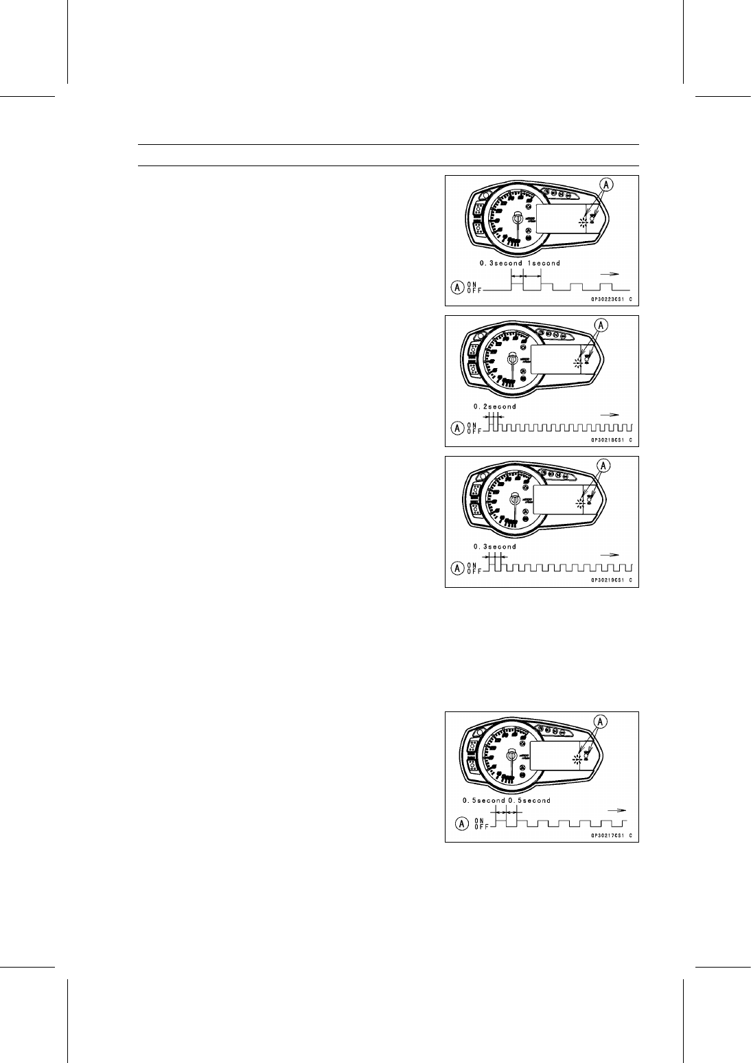
The red warning indicator light (LED) and immobilizer
warning symbol [A] blink 1 time and stops for 1 second
and repeats this cycle.

Not Verified

The red warning indicator light (LED) and immobilizer
warning symbol [A] blink to display the collation error.

Immobilizer Amplifier Failure

Registered Ignition Key Collation Error

Turn to “OFF” and remove the new ignition key 1.

NOTE

Insert the next key and turn it to “ON” within 15 sec-
onds after previous key is turned to “OFF” and removed
otherwise registration mode will be ended and the red
warning indicator light (LED) and immobilizer warning
symbol stops blinking.

Verified

The red warning indicator light (LED) and immobilizer
warning symbol [A] blink to display the ECU is in the
registration mode (go to the next step).

16-82 ELECTRICAL SYSTEM

Immobilizer System (Equipped Models)

Disconnect the immobilizer antenna connector, then con-
nect the antenna connector of the new ignition switch.

Insert the ignition key 1 [A] again into the new ignition
switch and turn it to “ON.”

NOTE

Insert the next key and turn it to “ON” within 15 sec-
onds after previous key is turned to “OFF” and removed
otherwise registration mode will be ended and the red
warning indicator light (LED) and immobilizer warning
symbol stops blinking.

To return to the registration mode start the registered
ignition key verification procedure. This applies to all
ignition key registration.

Keep other ignition keys away from the ignition switch.

If there is any problem in the registration, the red warning
indicator light (LED) and immobilizer warning symbol [A]
blink to display the collation error.

Immobilizer Amplifier Failure

When Registered Ignition Key is Inserted.

Ignition Key Collation Error

ELECTRICAL SYSTEM 16-83

Immobilizer System (Equipped Models)

The ignition key 1 is successfully registered in the ECU.

The red warning indicator light (LED) and immobilizer
warning symbol [A] blink 2 times and stops for 1 second
and then repeats this cycle to indicate successful regis-
tering of ignition key 1.

Turn to “OFF” and remove ignition key 1.

The red warning indicator light (LED) and immobilizer
warning symbol [A] blink to display the registration mode.

NOTE

Turn to “OFF” the ignition switch and wait for the period
more than 15 seconds. The registration mode automat-
ically ends and red warning indicator light (LED) goes
off.

This procedure has , registered the registered ignition
key and one ignition key.

Continue the procedure to program the second and
later keys.

Insert the ignition key 2 to the ignition switch and turn it to
“ON.”

If there is any problem in the registration, the red warning
indicator light (LED) and immobilizer warning symbol [A]
blink to display the collation error.

Immobilizer Amplifier Failure

When Registered Ignition Key is Inserted.

16-84 ELECTRICAL SYSTEM

Immobilizer System (Equipped Models)

Ignition Key Collation Error

The ignition key 2 is successfully registered in the ECU.

The red warning indicator light (LED) and immobilizer
warning symbol [A] blink 3 times and stops for 1 second
and then repeat this cycle to indicate successful pro-
gramming of ignition key 2.

Turn to “OFF” the ignition switch and wait for period more
than 15 seconds.

The registration mode automatically ends.

The red warning indicator light (LED) goes off [A].

Remove the key registration unit, key registration adapter
and install the immobilizer/Kawasaki diagnostic system
connector cap.

NOTE

Turn the ignition switch to “ON” with the registered igni-
tion key.

Check that the engine can be started using all regis-
tered ignition keys.

Install the new ignition switch (see Immobilizer System
Parts Replacement).

Case 3: When the ECU is faulty and has to be replaced.

Prepare a new ECU [A] and current registered ignition
key(s) [B].

NOTE

The key registration unit is not required.

After replacing the ECU, be sure to register the 2 ignition
keys. If the 2 keys are not registered, the engine can
not be started.

ELECTRICAL SYSTEM 16-85

Immobilizer System (Equipped Models)

Replace the ECU [A] (see ECU Removal/Installation in
the Fuel System (DFI) chapter).

Insert the current registered ignition key into the ignition
switch and turn it to “ON.”

If there is any problem in the registration, the red warning
indicator light (LED) and immobilizer warning symbol [A]
blink to display the collation error.

Immobilizer Amplifier Failure

Registered Ignition Key Collation Error

The registered ignition key is registered in the ECU.

The red warning indicator light (LED) and immobilizer
warning symbol [A] blink 1 time and stops for 1 second
and the repeats this cycle to indicate successful registra-
tion of the registered ignition key.

16-86 ELECTRICAL SYSTEM

Immobilizer System (Equipped Models)

Turn to “OFF” the registered ignition key and remove it.

The red warning indicator light (LED) and immobilizer
warning symbol [A] blink to display the registration mode.

NOTE

Insert next key and turn it to “ON” within 15 seconds af-
ter previous key is turned to “OFF” and removed other-
wise registration mode will be ended and the red warn-
ing indicator light (LED) goes off.

To return to the registration mode start the registered
ignition key verification procedure. This applies to all
ignition key registration.

Insert the other remaining registered ignition key to the
ignition switch and turn it to “ON.”

NOTE

Keep the other ignition keys away from the immobilizer
antenna.

If there is any problem in the registration, the red warning
indicator light (LED) and immobilizer warning symbol [A]
blink to display the collation error.

Immobilizer Amplifier Failure

When Registered Ignition Key is Inserted.

Ignition Key Collation Error

ELECTRICAL SYSTEM 16-87

Immobilizer System (Equipped Models)

The other remaining ignition key is registered in the ECU.

The red warning indicator light (LED) and immobilizer
warning symbol [A] blink 2 times and stops for 1 second
and then repeats this cycle to indicate successful regis-
tration of ignition key.

Turn to “OFF” the ignition switch and wait for period more
than 15 seconds.

The registration mode automatically ends.

The red warning indicator light (LED) goes off [A].

NOTE

Turn the ignition switch to “ON” with the registered igni-
tion key.

Check that the engine can be started using all regis-
tered ignition keys.

Case 4: When all registered ignition keys are faulty or
lost.

The all registered ignition keys replacement is considered

very rare case. However if it is required, the following is
necessary.

NOTE

The ECU must be replaced with a new one because
the registered ignition key code that is registered in the
current ECU can not be rewritten.

Prepare a new ECU [A] and 2 new ignition keys [B].

NOTE

The key registration unit is not required.

The key registration process is same as the electric con-
trol unit replacement.

Insert the first ignition key into the ignition switch and turn
it to “ON.”

16-88 ELECTRICAL SYSTEM

Immobilizer System (Equipped Models)

If there is any problem in the registration, the red warning
indicator light (LED) and immobilizer warning symbol [A]
blink to display the collation error.

Immobilizer Amplifier Failure

Ignition Key Collation Error

The first ignition key is registered in the ECU.

The red warning indicator light (LED) and immobilizer
warning symbol [A] blink 1 time and stops for 1 second
and the repeats this cycle to indicate successful registra-
tion of the first ignition key.

Turn to “OFF” the first ignition key and remove it.

The red warning indicator light (LED) and immobilizer
warning symbol [A] blink to display the registration mode.

NOTE

Insert next key and turn it to “ON” within 15 seconds af-
ter previous key is turned to “OFF” and removed other-
wise registration mode will be ended and the red warn-
ing indicator light (LED) goes off.

To return to the registration mode start the registered
ignition key verification procedure. This applies to all
ignition key registration.

Insert the second ignition key to the ignition switch and
turn it to “ON.”

NOTE

Keep the other ignition keys away from the immobilizer
antenna.

ELECTRICAL SYSTEM 16-89

Immobilizer System (Equipped Models)

If there is any problem in the registration, the red warning
indicator light (LED) and immobilizer warning symbol [A]
blink to display the collation error.

Immobilizer Amplifier Failure

When Registered Ignition Key is Inserted

Ignition Key Collation Error

The second ignition key is registered in the ECU.

The red warning indicator light (LED) and immobilizer
warning symbol [A] blink 2 times and stops for 1 second
and then repeats this cycle to indicate successful regis-
tration of second ignition key.

Turn to “OFF” the ignition switch and wait for period more
than 15 seconds.

The registration mode automatically ends.

Red warning indicator light (LED) [A] goes off.

16-90 ELECTRICAL SYSTEM

Immobilizer System (Equipped Models)

NOTE

Turn the ignition switch to “ON” with the registered igni-
tion key.

Check that the engine can be started using all regis-
tered ignition keys.

ELECTRICAL SYSTEM 16-91

Immobilizer System (Equipped Models)

All Keys Initial Registration Flow Chart

16-92 ELECTRICAL SYSTEM

Immobilizer System (Equipped Models)

Immobilizer System Parts Replacement

Ignition Switch Replacement

Remove:

Air Cleaner Housing (see Air Cleaner Housing Removal
in the Fuel System (DFI) chapter)

Open the clamp [A].

Disconnect the lead connectors [B].

Remove:

Steering Stem Head and Handlebars (see Handlebar
Removal in the Steering chapter)

Using a small chisel or punch [A], turn out the Torx bolts.

Pull out the ignition switch from the steering stem head.

Register the more than two ignition keys (see Key Regis-
tration).

Tighten a new Torx bolt [A] until the bolt head [B] is broken
[C].

Run the leads correctly (see Cable, Wire, and Hose Rout-
ing section in the Appendix chapter).

Immobilizer Amplifier Replacement

Remove the upper fairing assembly (see Upper Fairing
Assembly Removal in the Frame chapter).

Disconnect the connector [A].

Pull out the immobilizer amplifier [B] together with the rub-
ber protector [C] from the meter bracket.

ECU Replacement

Refer to the ECU Removal/Installation in the Fuel System
(DFI) chapter.

ELECTRICAL SYSTEM 16-93

Immobilizer System (Equipped Models)

Immobilizer Relational Parts Replacement Chart

Failed or Lost Part

Ignition

Key

Ignition

Switch

Amplifier

ECU

Ignition

Key

Ignition

Switch

Amplifier

*

ECU

*

Replacement Part

Main Replacement Part

Additional Replacement Part

Immobilizer System Inspection

Refer to the Immobilizer Amplifier and Blank Key Detec-
tion section in the Fuel System (DFI) chapter.

16-94 ELECTRICAL SYSTEM

Immobilizer System (Equipped Models)

Immobilizer System Circuit

1. Ignition Switch
2. Joint Connector D
3. ECU
4. Immobilizer/Kawasaki Diagnostic System Connector
5. Frame Ground 1
6. Engine Ground
7. Battery 12 V 8 Ah
8. Starter Relay
9. Main Fuse 30 A

10. Fuse Box 1

11. Ignition Fuse 15 A

12. Meter Unit
13. Red Warning Indicator Light (LED)
14. Joint Connector E
15. Immobilizer Antenna
16. Immobilizer Amplifier

ELECTRICAL SYSTEM 16-95

Switches and Sensors

Brake Light Timing Inspection

Refer to the Brake Light Switch Operation Inspection in
the Periodic Maintenance chapter.

Brake Light Timing Adjustment

Refer to the Brake Light Switch Operation Inspection in
the Periodic Maintenance chapter.

Switch Inspection

Using a hand tester, check to see that only the connec-
tions shown in the table have continuity.

Special Tool - Hand Tester: 57001-1394

For the switch housings and the ignition switch, refer to
the tables in the Wiring Diagram.
If the switch has an open or short, repair it or replace it
with a new one.

Rear Brake Light Switch Connections

Sidestand Switch Connections

Oil Pressure Switch Connections*

*: Engine lubrication system is in good condition.

16-96 ELECTRICAL SYSTEM

Switches and Sensors

Water Temperature Sensor Inspection

Remove the water temperature sensor (see Wa-
ter Temperature Sensor Removal/Installation in the
Self-Diagnosis System chapter).

Suspend the sensor [A] in a container of coolant so that
the temperature-sensing projection [C] is submerged.

Suspend an accurate thermometer [B] with temperature
-sensing projection located in almost the same depth with
the sensor.

NOTE

The sensor and thermometer must not touch the con-
tainer side or bottom.

Place the container over a source of heat and gradu-
ally raise the temperature of the coolant while stirring the
coolant gently.

Using the hand tester, measure the internal resistance of
the sensor.
If the hand tester does not show the specified values, re-
place the sensor.

Water Temperature Sensor Resistance

Temperature

Resistance (k

)

–20°C (–4°F)

*18.80 ±2.37

0°C (32°F)

*(about 6.544)

40°C (104°F)

1.136 ±0.095

100°C (212°F)

0.1553 ±0.0070

*: Reference Information

Fuel Reserve Switch Inspection

Fill the fuel tank with fuel and close the fuel tank cap.

Remove the front seat (see Front Seat Removal in the
Frame chapter).

Open the clamps.

Slide the dust cover [A].

Disconnect the fuel pump lead connector [B].

Connect the test light [A] (12 V 3.4 W bulb in a socket
with leads) and the 12 V battery [B] to the fuel pump lead
connector [C].

Connections:

Battery (+)

12 V 3.4 W Bulb (One Side)

12 V 3.4 W Bulb (Other Side)

R/BK lead [D]

Battery (–)

BK/W lead [E]

If the test light turn on, the reserve switch is defective.
Replace the fuel pump.

ELECTRICAL SYSTEM 16-97

Switches and Sensors

Draw the fuel out from the fuel tank with a commercially
available pump (see Fuel Tank Removal in the Fuel Sys-
tem (DFI) chapter).

Connect the test light (12 V 3.4 W bulb in a socket with
leads) and the 12 V battery to the fuel pump lead connec-
tor in the same way again.

Connections:

Battery (+)

12 V 3.4 W Bulb (One Side)

12 V 3.4 W Bulb (Other Side)

R/BK lead

Battery (–)

BK/W lead

If the test light does not light, replace the fuel pump.

NOTE

It may take a long time to turn on the test light in case
that the fuel reserve switch is inspected just after the
fuel is drawn. Leave the fuel pump lead connector with
leads for inspection connected for few minutes.

Oxygen Sensor Removal (Equipped Models)

Remove:

Fuel Tank (see Fuel Tank Removal in the Fuel System
(DFI) chapter)

Disconnect the oxygen sensor lead connector [A].

NOTICE

Do not pull strongly, twist, or bend the oxygen sen-
sor lead. This may cause the wiring open.

Free the lead [A] from the clamp.

Remove the oxygen sensor [B].

Oxygen Sensor Installation (Equipped Models)

NOTICE

Never drop the oxygen sensor [A] especially on a
hard surface. Such a shock to the unit can damage
it. Do not touch the sensing part [B] to prevent oil
contact. Oil contamination from hands can reduce
sensor performance.

Tighten:

Torque - Oxygen Sensor: 25 N·m (2.5 kgf·m, 18 ft·lb)

Run the oxygen sensor lead correctly (see Cable, Wire,
and Hose Routing section in the Appendix chapter).

Oxygen Sensor Inspection (Equipped Models)

Refer to the Oxygen Sensor Inspection in the Self
-Diagnosis System chapter.

16-98 ELECTRICAL SYSTEM

Switches and Sensors

Oxygen Sensor Heater Inspection (Equipped
Models)

Refer to the Oxygen Sensor Heater Resistance Inspec-
tion in the Self-Diagnosis System chapter.

Gear Position Switch Removal

Remove:

Engine Sprocket Cover (see Engine Sprocket Removal
in the Final Drive chapter)
Left Lower Fairing (see Lower Fairing Removal in the
Frame chapter)
Fuel Tank (see Fuel Tank Removal in the Fuel System
(DFI) chapter)

Disconnect the connector [A].

Open the clamps [A].

Remove:

Gear Position Switch Screws [A]
Holding Plate [B]
Gear Position Switch

Remove the pins [A] and springs from the shift drum.

ELECTRICAL SYSTEM 16-99

Switches and Sensors

Gear Position Switch Installation

Securely place the springs [A] and pins [B] into the holes
[C] of the shift drum.

Apply grease to the new O-ring [D].

Install the gear position switch [E] and holding plate [F].

Apply a non-permanent locking agent to the threads of
the gear position switch screws [G].

Tighten:

Torque - Gear Position Switch Screws: 2.9 N·m (0.30 kgf·m,

26 in·lb)

Run the lead [H] correctly (see Cable, Wire, and Hose
Routing section in the Appendix chapter).

Install the removed parts (see appropriate chapters).

Gear Position Switch Inspection

NOTE

Be sure the transmission and external shift mechanism
are good condition.

Remove the fuel tank (see Fuel Tank Removal in the Fuel
System (DFI) chapter).

Disconnect the connector [A].

16-100 ELECTRICAL SYSTEM

Switches and Sensors

Set the hand tester [A] to the × 1 k

or × 100

range

and connect it to the terminals in the connector [B] and
ground.

When changing the gear position from lower gear to
higher gear, raise the rear wheel off the ground with the
stand and rotate the rear wheel by hand.

Internal Circuit [C]
[1] LG Lead
[2] G/R Lead
[3] BK Lead

Special Tool - Hand Tester: 57001-1394

Gear Position Switch Resistance

(Unit: k

)

Connections

Gear

Position

[1]-Ground

[2]-Ground

[3]-Ground

Neutral

about 0

8.64

9.54

about 0

1st

2.22

2.46

about 0

2nd

1.42

1.58

about 0

3rd

0.955

1.055

about 0

4th

0.644

0.711

about 0

5th

0.410

0.453

about 0

6th

0.241

0.266

about 0

If the tester reading is not as specified, replace the gear
position switch with a new one.

ELECTRICAL SYSTEM 16-101

Relay Box

Relay Box Removal

Remove the front seat cover (see Seat Cover Removal in
the Frame chapter).

Disconnect the connectors [A].

Pull out the relay box [B] from the rubber protector [C].

NOTE

The relay box has relays and diodes. The relays and
diodes can not be removed.

Relay Circuit Inspection

Remove the relay box (see Relay Box Removal).

Check conductivity of the following numbered terminals
by connecting the hand tester and one 12 V battery to the
relay box as shown (see Relay Box Internal Circuit in this
section).
If the tester does not read as specified, replace the relay
box.

Relay Circuit Inspection (with the battery disconnected)

Tester Connection

Tester Reading (

)

Headlight Circuit
Relay

1-3

7-6

ECU Main Relay

4-5

Not

*

7-8

Fuel Pump Relay

9-10

Not

*

11-16

Starter Circuit Relay

11-12

17-20

Fan Relay

18-19

Not

*

*: The actual reading varies with the hand tester used.

Relay Circuit Inspection (with the battery connected)

Battery

Connection

(+)

(–)

Tester

Connection

Tester

Reading (

)

2-11

1-3

0

ECU Main Relay

4-5

7-6

0

Fuel Pump Relay

9-10

7-8

0

Fan Relay

18-19

17-20

0

Battery

Connection

(+)

(–)

Tester Connection

DC 25 V Range

(+)

(–)

Tester

Reading (V)

Starter
Circuit Relay

16-12

11-12

Battery

Voltage

(+): Apply positive lead.

(–): Apply negative lead.

16-102 ELECTRICAL SYSTEM

Relay Box

Diode Circuit Inspection

Remove the relay box (see Relay Box Removal).

Check conductivity of the following pairs of terminals (see
Relay Box Internal Circuit in this section).

Diode Circuit Inspection

Tester Connection

1-11, 2-11, 12-13, 12-15, 12-16, 13-14,
13-15

The resistance should be low in one direction and more
than 10 times as much in the other direction. If any diode
shows low or high in both directions, the diode is defective
and the relay box must be replaced.

NOTE

The actual meter reading varies with the meter or tester
used and the individual diodes, but generally speaking,
the lower reading should be from zero to one half the
scale.

Relay Box Internal Circuit

A: Headlight Circuit Relay
B: ECU Main Relay

C: Fuel Pump Relay
D: Starter Circuit Relay

E: Fan Relay

ELECTRICAL SYSTEM 16-103

Fuse

30 A Main/15 A ECU Fuse Removal

Remove:

Fuel Tank (see Fuel Tank Removal in the Fuel System
(DFI) chapter)
Starter Relay Cover [A]

Pull out the fuses [A] from the starter relay with needle
nose pliers.

Fuse Box Fuse Removal

Remove the left inner cover (see Inner Cover Removal in
the Frame chapter).

Unlock the hook [A] to lift up the lid.

Fuse Box 1 [B]
Fuse Box 2 [C]

Pull the fuses [A] straight out of the fuse box with needle
nose pliers.

Fuse Installation

If a fuse fails during operation, inspect the electrical sys-
tem to determine the cause, and then replace it with a
new fuse of proper amperage.

Install the fuse box fuses on the original position as spec-
ified on the lid.

16-104 ELECTRICAL SYSTEM

Fuse

Fuse Inspection

Remove the fuse (see 30 A Main/Fuse Box/10 A ECU
Fuse Removal).

Inspect the fuse element.
If it is blown out, replace the fuse. Before replacing a
blown fuse, always check the amperage in the affected
circuit. If the amperage is equal to or greater than the
fuse rating, check the wiring and related components for
a short circuit.

Housing [A]
Fuse Element [B]
Terminals [C]
Blown Element [D]

NOTICE

When replacing a fuse, be sure the new fuse
matches the specified fuse rating for that circuit.
Installation of a fuse with a higher rating may cause
damage to wiring and components.

SELF-DIAGNOSIS SYSTEM 17-1

17

Self-Diagnosis System

Table of Contents

Specifications .........................................................................................................................

17-4

Special Tools ..........................................................................................................................

17-6

Self-Diagnosis ........................................................................................................................

17-7

Self-Diagnosis Outline ......................................................................................................

17-7

Self-Diagnosis Procedures ...............................................................................................

17-8

Self-Diagnosis Flow Chart ................................................................................................

17-10

Service Code Reading ......................................................................................................

17-11

Service Code Erasing .......................................................................................................

17-11

Backups ............................................................................................................................

17-13

Main Throttle Sensor (Service Code 11) ................................................................................

17-16

Main Throttle Sensor Removal/Adjustment ......................................................................

17-16

Main Throttle Sensor Input Voltage Inspection .................................................................

17-16

Main Throttle Sensor Resistance Inspection ....................................................................

17-17

Main Throttle Sensor Output Voltage Inspection ..............................................................

17-17

Intake Air Pressure Sensor #1 (Service Code 12)..................................................................

17-20

Intake Air Pressure Sensor #1 Removal...........................................................................

17-20

Intake Air Pressure Sensor #1 Installation........................................................................

17-20

Intake Air Pressure Sensor #1 Input Voltage Inspection...................................................

17-21

Intake Air Pressure Sensor #1 Output Voltage Inspection................................................

17-22

Intake Air Temperature Sensor (Service Code 13).................................................................

17-26

Intake Air Temperature Sensor Removal ..........................................................................

17-26

Intake Air Temperature Sensor Installation .......................................................................

17-26

Intake Air Temperature Sensor Output Voltage Inspection ...............................................

17-27

Intake Air Temperature Sensor Resistance Inspection .....................................................

17-28

Water Temperature Sensor (Service Code 14) ......................................................................

17-29

Water Temperature Sensor Removal/Installation .............................................................

17-29

Water Temperature Sensor Output Voltage Inspection.....................................................

17-29

Water Temperature Sensor Resistance Inspection...........................................................

17-30

Intake Air Pressure Sensor #2 (Service Code 16)..................................................................

17-31

Intake Air Pressure Sensor #2 Removal...........................................................................

17-31

Intake Air Pressure Sensor #2 Installation........................................................................

17-31

Intake Air Pressure Sensor #2 Input Voltage Inspection...................................................

17-32

Intake Air Pressure Sensor #2 Output Voltage Inspection................................................

17-33

Crankshaft Sensor (Service Code 21)....................................................................................

17-35

Crankshaft Sensor Removal/Installation...........................................................................

17-35

Crankshaft Sensor Resistance Inspection ........................................................................

17-35

Crankshaft Sensor Peak Voltage Inspection.....................................................................

17-35

Rear Wheel Rotation Sensor Signal (Service Code 24).........................................................

17-37

Rear Wheel Rotation Sensor Signal Inspection................................................................

17-37

Gear Position Switch (Service Code 25) ................................................................................

17-40

Gear Position Switch Removal/Installation .......................................................................

17-40

Gear Position Switch Resistance Inspection ....................................................................

17-40

Gear Position Switch Output Voltage Inspection ..............................................................

17-40

Front Wheel Rotation Sensor Signal (Service Code 27) ........................................................

17-42

Front Wheel Rotation Sensor Signal Inspection ...............................................................

17-42

Vehicle-down Sensor (Service Code 31)................................................................................

17-45

Vehicle-down Sensor Removal .........................................................................................

17-45

Vehicle-down Sensor Installation ......................................................................................

17-45

Vehicle-down Sensor Input Voltage Inspection.................................................................

17-46

Vehicle-down Sensor Output Voltage Inspection ..............................................................

17-47

17-2 SELF-DIAGNOSIS SYSTEM

Subthrottle Sensor (Service Code 32)....................................................................................

17-49

Subthrottle Sensor Removal/Adjustment ..........................................................................

17-49

Subthrottle Sensor Input Voltage Inspection.....................................................................

17-49

Subthrottle Sensor Output Voltage Inspection ..................................................................

17-50

Subthrottle Sensor Resistance Inspection ........................................................................

17-52

Oxygen Sensor - not activated (Service Code 33, Equipped Models) ...................................

17-53

Oxygen Sensor Removal/Installation................................................................................

17-53

Oxygen Sensor Inspection................................................................................................

17-53

Exhaust Butterfly Valve Actuator Sensor (Service Code 34)..................................................

17-57

Exhaust Butterfly Valve Actuator Sensor Removal/Installation.........................................

17-57

Exhaust Butterfly Valve Actuator Sensor Input Voltage Inspection...................................

17-57

Exhaust Butterfly Valve Actuator Sensor Output Voltage Inspection ................................

17-58

Exhaust Butterfly Valve Actuator Sensor Resistance Inspection ......................................

17-59

Immobilizer Amplifier (Service Code 35, Equipped Models) ..................................................

17-60

Antenna Resistance Inspection ........................................................................................

17-60

Amplifier Input Voltage Inspection.....................................................................................

17-60

Blank Key Detection (Service Code 36, Equipped Models) ...................................................

17-61

Ignition Key Inspection......................................................................................................

17-61

ECU Communication Error (Service Code 39) .......................................................................

17-62

ECU Communication Line Inspection ...............................................................................

17-62

Stick Coils #1, #2, #3, #4: (Service Code 51, 52, 53, 54) ......................................................

17-64

Stick Coil Removal/Installation..........................................................................................

17-64

Stick Coil Primary Winding Resistance Inspection ...........................................................

17-64

Stick Coil Input Voltage Inspection....................................................................................

17-64

Radiator Fan Relay (Service Code 56)...................................................................................

17-66

Radiator Fan Relay Removal/Installation..........................................................................

17-66

Radiator Fan Relay Inspection..........................................................................................

17-66

Subthrottle Valve Actuator (Service Code 62) ........................................................................

17-67

Subthrottle Valve Actuator Removal .................................................................................

17-67

Subthrottle Valve Actuator Inspection ...............................................................................

17-67

Subthrottle Valve Actuator Resistance Inspection ............................................................

17-67

Subthrottle Valve Actuator Input Voltage Inspection .........................................................

17-68

Exhaust Butterfly Valve Actuator (Service Code 63) ..............................................................

17-70

Exhaust Butterfly Valve Actuator Removal .......................................................................

17-70

Exhaust Butterfly Valve Actuator Installation ....................................................................

17-70

Exhaust Butterfly Valve Actuator Inspection .....................................................................

17-72

Exhaust Butterfly Valve Actuator Resistance Inspection ..................................................

17-73

Air Switching Valve (Service Code 64) ...................................................................................

17-74

Air Switching Valve Removal/Installation ..........................................................................

17-74

Air Switching Valve Inspection ..........................................................................................

17-74

Oxygen Sensor Heater (Service Code 67, Equipped Models) ...............................................

17-75

Oxygen Sensor Heater Removal/Installation ....................................................................

17-75

Oxygen Sensor Heater Resistance Inspection .................................................................

17-75

Oxygen Sensor Heater Power Source Voltage Inspection ...............................................

17-76

Oxygen Sensor - Incorrect Output Voltage (Service Code 94 (Equipped Models))................

17-78

Oxygen Sensor Removal/Installation................................................................................

17-78

Oxygen Sensor Inspection................................................................................................

17-78

KIBS Hydraulic Unit Communication Error (Service Code 1b, KIBS Equipped Models) ........

17-81

KIBS Hydraulic Unit Communication Line Inspection .......................................................

17-81

Purge Valve (Service Code 3A) (CAL Model).........................................................................

17-83

Purge Valve Removal/Installation .....................................................................................

17-83

Purge Valve Inspection .....................................................................................................

17-83

KIBS Service Codes (KIBS Equipped Models).......................................................................

17-86

Solenoid Valve Inspection (Service Code b 13, b 14, b 17, b 18).....................................

17-86

KIBS Solenoid Valve Relay Inspection (Service Code b 19) ............................................

17-86

Front, Rear Wheel Rotation Difference Abnormal Inspection (Service Code b 25) ..........

17-86

KIBS Motor Relay Inspection (Service Code b 35) ...........................................................

17-86

17-4 SELF-DIAGNOSIS SYSTEM

Specifications

Item

Standard

Digital Fuel Injection System

Main Throttle Sensor:

Input Voltage

DC 4.75

5.25 V

Output Voltage

DC 1.02

1.06 V at idle throttle opening

DC 4.30

4.34 V at full throttle opening (for reference)

Resistance

4

6 k

Intake Air Pressure Sensor #1/#2:

Input Voltage

DC 4.75

5.25 V

Output Voltage

DC 3.80

4.20 V at standard atmospheric pressure (see

this text for details)

Intake Air Temperature Sensor:

Output Voltage

About DC 2.25

2.50 V at 20°C (68°F)

Resistance

5.4

6.6 k

at 0°C (32°F)

0.29

0.39 k

at 80°C (176°F)

Water Temperature Sensor:

Output Voltage

About DC 2.80

2.97 V at 20°C (68°F)

Vehicle-down Sensor:

Input Voltage

DC 4.75

5.25 V

Output Voltage

with sensor tilted 60

70° or more right or left: DC 0.65

1.35 V

with sensor arrow mark pointed up: DC 3.55

4.45 V

Subthrottle Sensor:

Input Voltage

DC 4.75

5.25 V

Output Voltage

DC 1.08

1.12 V at subthrottle valve full close position

DC 4.48

4.52 V at subthrottle valve full open position

(for reference)

Resistance

4

6 k

Subthrottle Valve Actuator:

Resistance

About 5.2

7.8

Input Voltage

About DC 8.5

10.5 V and then 0 V or

About DC 8.5

10.5 V

Oxygen Sensor (Equipped Models):

Output Voltage (Rich)

DC 0.8 V or more

Output Voltage (Lean)

DC 0.24 V or less

Heater Resistance

6.7

10.5

at 20°C (68°F)

Exhaust Butterfly Valve Actuator
Sensor:

Input Voltage

DC 4.75

5.25 V

Output Voltage

DC 3.46

3.76 V at pulley original position

Resistance

4

6 k

Immobilizer Antenna (Equipped
Models):

Resistance

About 3.0

4.6

Exhaust Butterfly Valve Actuator:

Resistance

5

200

(for reference)

SELF-DIAGNOSIS SYSTEM 17-5

Specifications

Item

Standard

Purge Valve:

Resistance

30

34

at 20°C (68°F)

KIBS System (Equipped Models)

Wheel Rotation Sensor Air Gap:

Front

0.4

1.6 mm (0.02

0.06 in.)

Rear

0.4

1.6 mm (0.02

0.06 in.)

CAN Communication Line
Resistance

30

70

CAN Communication Line/Ground
Resistance

5

30 k

17-6 SELF-DIAGNOSIS SYSTEM

Special Tools

Fork Oil Level Gauge:
57001-1290

Vacuum Gauge:
57001-1369

Hand Tester:
57001-1394

Throttle Sensor Setting Adapter #1:
57001-1400

Peak Voltage Adapter:
57001-1415

Needle Adapter Set:
57001-1457

Throttle Sensor Setting Adapter:
57001-1538

Extension Tube:
57001-1578

Measuring Adapter:
57001-1700

SELF-DIAGNOSIS SYSTEM 17-7

Self-Diagnosis

Self-Diagnosis Outline

The self-diagnosis system is monitoring the following

mechanisms.

DFI System and Ignition System
KTRC System
Immobilizer System (Equipped Models)
KIBS and ABS (Equipped Models)

The following indicator lights (LED) are used for symbols

of below table.

LED Color

Indicator Symbols

Red [A]

Oil Pressure
Battery
Immobilizer (Equipped Models)

Yellow [B]

FI

Yellow [C]

KTRC

Yellow [D]

KTRC
KIBS (Equipped Models)

Yellow [E]

ABS (Equipped Models)

ZX636E Model [F]
ZX636F Model [G]

The self-diagnosis system has two modes and can be

switched to another mode by operating the meter unit.

User Mode

The ECU notifies the rider of troubles in DFI system,

ignition system, KTRC system and immobilizer system
(equipped models) by lighting or blinking the yellow engine
warning indicator light (LED) [A], red warning indicator light
(LED) [B], yellow KTRC warning indicator light (LED) [C],
yellow warning indicator light [D] and warning symbols [E]
when DFI, ignition, KTRC and immobilizer system parts
are faulty, and initiates fail-safe function. In case of serious
troubles, ECU stops the injection and ignition operations.

ZX636E Model [F]
ZX636F Model [G]

17-8 SELF-DIAGNOSIS SYSTEM

Self-Diagnosis

For KIBS and ABS system (equipped models), the KIBS

hydraulic unit notifies the rider of troubles in KIBS and ABS
system by lighting or blinking the yellow ABS indicator light
(LED) [A], yellow warning indicator light (LED) [B] and KIBS
warning symbol [C] when KIBS and ABS parts are faulty,
and initiates fail-safe function.

Dealer Mode

The LCD (Liquid Crystal Display) displays the service

code(s) [A] to show the problem(s) which the above system
has at the moment of diagnosis.

Self-Diagnosis Procedures

NOTE

Use

a

fully

charged

battery

when

conducting

self-diagnosis. Otherwise, the light (LED) and symbol
do not light or blink.

Turn the ignition switch on.

When a problem occurs with DFI system and ignition sys-
tem, the yellow engine warning indicator light (LED) [A]
goes on to alert the rider.

For models equipped with KTRC system, the yellow en-
gine warning indicator light (LED), yellow KTRC warn-
ing indicator light (LED) [B], yellow warning indicator light
(LED) [C] and KTRC warning symbol [D] go on, when a
problem occurs in the system.

ZX636E Model [E]
ZX636F Model [F]

When a problem occurs with immobilizer system
(equipped models), the red warning indicator light
(LED) [A] and immobilizer warning symbol [B] blink.


Content      ..     17      18      19      20     ..