Kawasaki Motorcycle Ninja ZX-6R / Ninja ZX-6R ABS. Service Manual (2013 year) - page 18
 

  Index      Manuals     Kawasaki Motorcycle Ninja ZX-6R / Ninja ZX-6R ABS. Service Manual (2013 year)


Search            copyright infringement  


Content      ..     16      17      18      19     ..


Kawasaki Motorcycle Ninja ZX-6R / Ninja ZX-6R ABS. Service Manual (2013 year) - page 18


ELECTRICAL SYSTEM 16-49

Electric Starter System

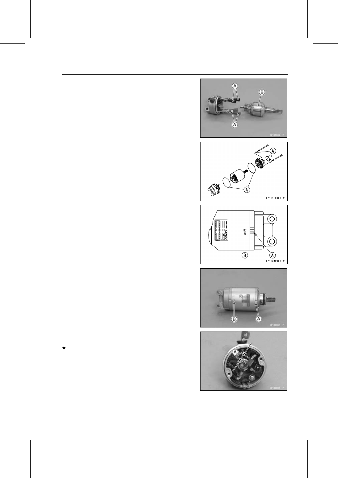
Press the springs holding the brush leads with suitable
clips [A] as shown.

Put the armature [B] among the brushes.

Install the new O-rings [A] as shown.

Align the groove [A] in the left-hand end cover and the
hollow mark [B] on the yoke.

Align the hollow mark [A] on the right-hand end cover and
the hollow mark [B] on the yoke.

Brush Inspection

Measure the length [A] of each brush.
If any is worn down to the service limit, replace the left
-hand end cover assembly.

Starter Motor Brush Length

Standard:

7 mm (0.28 in.)

Service Limit: 5 mm (0.20 in.)

16-50 ELECTRICAL SYSTEM

Electric Starter System

Commutator Cleaning and Inspection

Smooth the commutator surface [A] if necessary with fine
emery cloth [B], and clean out the grooves.

Measure the diameter [A] of the commutator [B].
If the commutator diameter is less than the service limit,
replace the starter motor with a new one .

Commutator Diameter

Standard:

24 mm (0.94 in.)

Service Limit: 23 mm (0.91 in.)

Armature Inspection

Using the × 1

hand tester range, measure the resis-

tance between any two commutator segments [A].

Special Tool - Hand Tester: 57001-1394

If there is a high resistance or no reading (

) between any

two segments, a winding is open and the starter motor
must be replaced.

Using the highest hand tester range, measure the resis-
tance between the segments and the shaft [B].
If there is any reading at all, the armature has a short and
the starter motor must be replaced.

NOTE

Even if the foregoing checks show the armature to be
good, it may be defective in some manner not readily
detectable with the hand tester. If all other starter motor
and starter motor circuit components check good, but
the starter motor still does not turn over or only turns
over weakly, replace the starter motor with a new one.

Brush Lead Inspection

Using the × 1

hand tester range, measure the resis-

tance as shown.

Terminal and Positive Brush [A]
Left-hand End Cover and Negative Brush [B]

Special Tool - Hand Tester: 57001-1394

If there is not close to zero ohms, the brush lead has an
open. Replace the left-hand end cover assembly.

ELECTRICAL SYSTEM 16-51

Electric Starter System

Left-hand End Cover Assembly Inspection

Using the highest hand tester range, measure the resis-
tance as shown.

Terminal and Left-hand End Cover [A]

Special Tool - Hand Tester: 57001-1394

If there is any reading, the left-hand end cover assembly
have a short. Replace the left-hand end cover assembly.

Starter Relay Inspection

Remove the battery negative (–) cable from the battery
negative (–) terminal (see Battery Removal).

Remove the fuel tank (see Fuel Tank Removal in the Fuel
System (DFI) chapter).

Remove the starter relay cover [A].

Disconnect the starter motor cable [A] and battery positive
(+) cable [B].

Remove the starter relay [C] from the rear fender.

Disconnect the connector [D].

Connect the hand tester [A] and 12 V battery [B] to the
starter relay [C] as shown.

Special Tool - Hand Tester: 57001-1394

If the relay does not work as specified, the relay is defec-
tive. Replace the relay.

Testing Relay

Tester Range:

× 1

range

Criteria:

When battery is connected

0

When battery is disconnected

→ ∞ Ω

16-52 ELECTRICAL SYSTEM

Electric Starter System

Electric Starter Circuit

1. Ignition Switch
2. Engine Stop Switch
3. Starter Button
4. Gear Position Switch
5. Sidestand Switch
6. Joint Connector D
7. Joint Connector B
8. Frame Ground 3
9. Frame Ground 1

10. Engine Ground

11. Battery 12 V 8 Ah

12. Starter Relay
13. Main Fuse 30 A
14. Starter Motor
15. Relay Box
16. Starter Circuit Relay
17. Starter Lockout Switch
18. Fuse Box 1
19. Ignition Fuse 15 A
20. Joint Connector E

ELECTRICAL SYSTEM 16-53

Lighting System

This motorcycle adopt the daylight system and have a

headlight relay in the relay box. The headlight does not
go on when the ignition switch and the engine stop switch
are first turned on. The headlight comes on after the starter
button is released and stays on until the ignition switch is
turned off. The headlight will go out momentarily whenever
the starter button is pressed and come back on when the
button is released.

Headlight Beam Horizontal Adjustment

Refer to the Headlight Aiming Inspection in the Periodic
Maintenance chapter.

Headlight Beam Vertical Adjustment

Refer to the Headlight Aiming Inspection in the Periodic
Maintenance chapter.

Headlight Bulb Replacement

Disconnect:

Dust Cover [A]

Disconnect:

Headlight Connector [A]
Hook [B]

Remove:

Headlight Bulb

NOTICE

When handling the quartz-halogen bulb, never
touch the glass portion with bare hands. Always
use a clean cloth. Oil contamination from hands or
dirty rags can reduce bulb life or cause the bulb to
explode.

NOTE

Clean off any contamination that inadvertently gets on
the bulb with alcohol or soap and water solution.

Replace the headlight bulb with a new one.

Fit the projection [A] of the bulb in the hollow [B] of the
headlight.

Install the hook.

16-54 ELECTRICAL SYSTEM

Lighting System

Connect the headlight connector.

Install the dust cover [A].

After installation, adjust the headlight aim (see Headlight
Aiming Inspection in the Periodic Maintenance chapter).

Other Bulb: Repeat the above steps.

City Light Bulb Replacement

Remove the inner cover (see Inner Cover Removal in the
Frame chapter).

Pull out the socket [A] together with the bulb.

Pull the bulb [A] out of the socket [B].

NOTICE

Do not turn the bulb. Pull the bulb out to prevent
damage to the bulb.

Do not use bulb rated for

greater wattage than the specified value.

Replace the bulb with a new one.

Insert the socket [A] to the headlight.

Other Bulb: Repeat the above steps.

Headlight Removal/Installation

Remove:

Upper Fairing Assembly (see Upper Fairing Assembly
Removal in the Frame chapter)
Bolts [A] and Clamps
Screws [B]
Headlight [C]

Installation is the reverse of removal.

ELECTRICAL SYSTEM 16-55

Lighting System

Tail/Brake Light (LED) Removal/Installation

Remove:

Tail/Brake Light Cover (see Rear Fender Removal in the
Frame chapter)

Slide the dust cover [A].

Open the clamp [B].

Disconnect the tail/brake light lead connector [C].

Remove:

Bolts [D] and Clamp
Tail/Brake Light (LED) [E]

Installation is the reverse of removal.

Run the lead correctly (see Cable, Wire, and Hose Rout-
ing section in the Appendix chapter).

License Plate Light Bulb Replacement

Remove:

License Plate Light Cover Screws [A]
License Plate Light Cover [B]

Pull the bulb [A] out of the socket [B].

NOTICE

Do not turn the bulb. Pull the bulb out to prevent
damage to the bulb.

Do not use bulb rated for

greater wattage than the specified value.

Replace the bulb with a new one.

Tighten:

Torque - License Plate Light Cover Screws: 1.0 N·m (0.10

kgf·m, 8.9 in·lb)

16-56 ELECTRICAL SYSTEM

Lighting System

Headlight/Tail Light Circuit

1. Ignition Switch
2. Frame Ground 1
3. Tail/Brake Light (LED)
4. License Plate Light 12 V 5 W
5. Joint Connector B
6. Frame Ground 3
7. Frame Ground 2
8. Engine Ground
9. Battery 12 V 8 Ah

10. Starter Relay

11. Main Fuse 30 A

12. Alternator
13. Regulator/Rectifier
14. Relay Box

15. Headlight Circuit Relay
16. Fuse Box 1
17. Brake Light/Horn Fuse 7.5 A
18. Ignition Fuse 15 A
19. Dimmer Switch
20. Passing Button
21. Left City Light 12 V 5 W
22. Headlight (HI) 12 V 55 W
23. Headlight (LO) 12 V 55 W
24. Right City Light 12 V 5 W
25. Joint Connector A
26. Meter Unit
27. Blue High Beam Indicator Light (LED)

ELECTRICAL SYSTEM 16-57

Lighting System

Turn Signal Light Bulb Replacement

Front Turn Signal Light

Remove:

Upper Fairing Assembly (see Upper Fairing Assembly
Removal in the Frame chapter)
Front Turn Signal Light Screws [A]
Front Turn Signal Light [B]

Turn the socket [A] counterclockwise and pull out the
socket together with the bulb.

Push and turn the front turn signal light bulb [A] counter-
clockwise and remove it.

Replace the bulb with a new one.

Insert the new bulb [A] by aligning its left and right pins [B]
with the left and right grooves [C] in the socket, and turn
the bulb clockwise.

Turn the bulb about 15°.

Fit the large projection [A] of the socket into the large
groove [B] of the turn signal light.

Small Projection [C]

Turn the front turn signal light bulb clockwise.

16-58 ELECTRICAL SYSTEM

Lighting System

Install:

Front Turn Signal Light [A]
Bracket [B]

Tighten:

Torque - Front Turn Signal Light Mounting Screws [C]: 1.2

N·m (0.12 kgf·m, 11 in·lb)

Other Bulb: Repeat the above steps.

Rear Turn Signal Light

Remove:

Screw [A]
Rear Turn Signal Light Lens

Push and turn the rear turn signal light bulb [A] counter-
clockwise and remove it.

Replace the bulb with a new one.

Insert the new bulb [A] by aligning its left and right pins [B]
with the left and right grooves [C] in the socket, and turn
the bulb clockwise.

Turn the bulb about 15°.

Fit the projection [A] of the lens into the groove [B] of the
turn signal light.

Tighten the screw.

Other Bulb: Repeat the above steps.

ELECTRICAL SYSTEM 16-59

Lighting System

Turn Signal Relay Inspection

Remove the front seat cover (see Seat Cover Removal in
the Frame chapter).

Pull out the turn signal relay [A] backward, and remove it
from the rear fender.

Disconnect the connector.

Connect one 12 V battery and turn signal lights as indi-
cated, and count how many times the lights blink for one
minute.

Turn Signal Relay [A]
Turn Signal Lights [B]
12 V Battery [C]

If the lights do not blink as specified, replace the turn sig-
nal relay.

Testing Turn Signal Relay

Load

The Number of Turn

Signal Lights

Wattage (W)

Blinking Times

(c/m*)

1**

10

140

250

2

20

75

95

(*): Cycle(s) per minute

(**): Corrected to “one light burned out”.

16-60 ELECTRICAL SYSTEM

Lighting System

Turn Signal Light Circuit

1. Ignition Switch
2. Rear Right Turn Signal Light 12 V 10 W
3. Rear Left Turn Signal Light 12 V 10 W
4. Joint Connector B
5. Frame Ground 3
6. Frame Ground 1
7. Engine Ground
8. Battery 12 V 8 Ah
9. Starter Relay

10. Main Fuse 30 A

11. Turn Signal Relay

12. Turn Signal Switch
13. Fuse Box 2
14. Turn Signal Relay Fuse 7.5 A
15. Front Left Turn Signal Light 12 V 10 W
16. Front Right Turn Signal Light 12 V 10 W
17. Joint Connector A
18. Meter Unit
19. Green Turn Signal Indicator Light (LED)

ELECTRICAL SYSTEM 16-61

Air Switching Valve

Air Switching Valve Operation Test

Refer to the Air Suction System Damage Inspection in the
Periodic Maintenance chapter.

Air Switching Valve Unit Test

Remove the air switching valve (see Air Switching Valve
Removal in the Engine Top End chapter).

Set the hand tester [A] to the × 1

range and connect it

to the air switching valve terminals as shown.

Special Tool - Hand Tester: 57001-1394

Air Switching Valve Resistance

Standard:

20

24

at 20°C (68°F)

If the resistance reading is out of the specified value, re-
place it with a new one.

Connect the 12 V battery [A] to the air switching valve
terminals as shown.

Blow the air to the intake air duct [A], and make sure does
not flow the blown air from the outlet air ducts [B].

Disconnect the 12 V battery.

Blow the air to the intake air duct [A] again, and make sure
flow the blown air from the outlet air ducts [B].
If the air switching valve dose not operate as described,
replace it with a new one.

NOTE

To check air flow through the air switching valve, just
blow through the air switching valve hose (intake side)
[C].

16-62 ELECTRICAL SYSTEM

Air Switching Valve

Air Switching Valve Circuit

1. Ignition Switch
2. Air Switching Valve
3. Joint Connector D
4. ECU
5. Frame Ground 3
6. Engien Ground
7. Battery 12 V 8 Ah
8. Starter Relay
9. Main Fuse 30 A

10. ECU Fuse 15 A

11. Frame Ground 1

12. Relay Box
13. ECU Main Relay
14. Fuse Box 1
15. Ignition Fuse 15 A
16. Joint Connector E

ELECTRICAL SYSTEM 16-63

Radiator Fan System

Fan Motor Inspection

Remove the air cleaner housing (see Air Cleaner Housing
Removal in the Fuel System (DFI) chapter).

Slide the dust cover [A].

Disconnect the connector [B].

Using an auxiliary leads, supply battery power to the fan
motor.
If the fan does not rotate, the fan motor is defective and
must be replaced.

Radiator Fan Circuit

1. Ignition Switch
2. Fan Motor
3. Water Temperature Sensor
4. Water-proof Joint 2
5. Joint Connector D
6. ECU
7. Frame Ground 3
8. Engine Ground
9. Battery 12 V 8 Ah

10. Starter Relay

11. Main Fuse 30 A

12. Frame Ground 1
13. Relay Box
14. Radiator Fan Relay
15. Fuse Box 1
16. Ignition Fuse 15 A
17. Fan Fuse 15 A
18. Joint Connector E

16-64 ELECTRICAL SYSTEM

Meter, Gauge, Indicator Unit

Meter Unit Removal/Installation

Remove:

Upper Fairing Assembly (see Upper Fairing Assembly
Removal in the Frame chapter)

Disconnect:

Meter Unit Connector [A]
Immobilizer Amplifier Connector [B] (Equipped Models)

Remove the bolts [C].

Remove:

Bolts [A]
Collar
Meter Bracket with Meter Unit [B]

Remove:

Meter Unit Mounting Screws [A]
Meter Unit [B]

NOTICE

Place the meter unit so that the face is up. If a meter
unit is left upside down or sideways for any length
of time, it will malfunction.

Installation is the reverse of removal.

Tighten:

Torque - Meter Unit Mounting Screws: 1.2 N·m (0.12 kgf·m,

11 in·lb)

Run the lead correctly (see Cable, Wire, and Hose Rout-
ing section in the Appendix chapter).

Meter Unit Disassembly

Remove:

Meter Unit (see Meter Unit Removal/Installation)
Screws [A]
Lower Meter Cover [B]

ELECTRICAL SYSTEM 16-65

Meter, Gauge, Indicator Unit

Separate the meter assembly [A] and upper meter cover
[B].

Meter Operation Inspection

Check 1-1: Switching Inspection

Turn the ignition switch on.

Check that the following.

ZX636E Model [A]
ZX636F Model [B]

The following Indicator lights (LED) go on for 1 second.

Yellow Shift Up Indicator Light (LED) [C]
Yellow Engine Warning Indicator Light (LED) [D]
Amber Fuel Level Warning Indicator Light (LED) [E]
Yellow KTRC Warning Indicator Light (LED) [F]
Yellow Warning Indicator Light (LED) [G]

The all LCD segments [H] appear for 3 seconds.

The tachometer needle [I] momentarily points their last
readings and back to the minimum position.

The yellow ABS indicator light [J] and the red warning
indicator light [K] go on.

If the meter unit does not work, replace the meter unit.

Refer to the Meter Unit Inspection for other indicator lights
(LED) inspection.

By pushing the MODE button each time, check that the
display [A] changes as follows.

16-66 ELECTRICAL SYSTEM

Meter, Gauge, Indicator Unit

Indicate the ODO mode.

By pushing the RESET button each time while the MODE
button pushed in, check that the display [A] changes as
follows.

NOTE

Mile/Km Display can alternate between English and
metric modes (mile and km) in the digital meter. Make
sure that km or mile according to local regulations is
correctly displayed before riding.

If the display function does not work, replace the meter
unit.

By pushing (0.3

0.4 seconds) the KTRC button [A] at

the left handlebar switch housing each time, check that
the KTRC indicator symbol changes to going on.
If the indicator symbol does not work, check the following
parts.

KTRC Button (see Switch Inspection)
Wiring (see Meter Unit Circuit)

If the above parts are good, replace the meter unit and/or
ECU.

ELECTRICAL SYSTEM 16-67

Meter, Gauge, Indicator Unit

By pushing (0.3

0.4 seconds) the power mode button

[A] at the left handlebar switch housing each time, check
that the power mode symbol changes to going on.
If the display function does not work, check the following
parts.

Power Mode Button (see Switch Inspection)
Wiring (see Meter Unit Circuit)

If the above parts are good, replace the meter unit and/or
ECU.

Check 1-2: Gear Position Indication Inspection

Turn the ignition switch on.

The green neutral indicator light (LED) [A] goes on when
the transmission gear is neutral position.

Set the low gear position, and check that the display
changes to 1 mark [A] and the green neutral indicator
light (LED) goes off.

Using the suitable stand, raise the rear wheel off the
ground.

Rotate the rear wheel by hand or start the engine, and
change the gear position.

Check that the display corresponding to each gear posi-
tion (1, 2, 3, 4, 5 or 6) appears.
If the display function does not work, check the following
parts.

Gear Position Switch (see Gear Position Switch Inspec-
tion)
Wiring (see Meter Unit Circuit)

If the above parts are good, replace the meter unit and/or
ECU.

16-68 ELECTRICAL SYSTEM

Meter, Gauge, Indicator Unit

Meter System Inspection

Check 2-1: Speedometer Inspection

Using the suitable stand, raise the rear wheel off the
ground.

Rotate the rear wheel by hand or start the engine.

Check that the display changes speedometer.
If the display function does not work, check the following
parts.

Rear Wheel Rotation Sensor (see Wheel Rotation Sen-
sor Inspection in the Brakes chapter)
ECU (ECU Power Supply Inspection in the Fuel System
(DFI) chapter)
Wiring (see Meter Unit Circuit)

If the above parts are good, replace the meter unit.

Check 2-2: Fuel Level Warning Inspection

Disconnect the fuel pump lead connector [A] (see Fuel
Tank Removal in the Fuel System (DFI) chapter).

Main Harness [B]

Connect the resistor [C] (about 100

) to the fuel pump

lead connector terminal as shown in the figure.

Turn the ignition switch on.

After about 5 seconds, amber fuel level warning indicator
light (LED) [A] goes on and “FUEL” [B] blinks.
If the display and indicator light (LED) function does not
work, replace the meter unit.

ELECTRICAL SYSTEM 16-69

Meter, Gauge, Indicator Unit

Meter Unit Inspection

Remove the meter unit (see Meter Unit Removal).

[1] Unused
[2] Unused
[3] Unused
[4] Unused
[5] Unused
[6] Unused
[7] Blue High Beam Indicator Light (LED) (+)
[8] Green Neutral Indicator Light (LED) (–)
[9] Green Turn Signal Indicator Light (LED) (+) for Left

[10] Green Turn Signal Indicator Light (LED) (+) for Right

[11] Unused

[12] Ground (–)
[13] Battery (+)
[14] Ignition
[15] CAN Communication Line (Low)
[16] CAN Communication Line (High)
[17] Oil Pressure Sensor Switch (–)
[18] Fuel Reserve Switch
[19] Power Mode Button
[20] KTRC Button

NOTICE

Do not drop the meter unit. Place the meter unit so
that it faces upward. If the meter assembly is left up-
side down or sideways for a long time or dropped,
it will malfunction. Do not short each terminals.

Check 3-1: CAN Communication Line Resistance In-
spection

Set the hand tester [A] to the ×1

range and connect it

to the terminal [15] and [16] in the meter unit.

Special Tool - Hand Tester: 57001-1394

CAN Communication Line Resistance (at Meter Unit)

Standard:

122

126

If the tester reading is not specified, replace the meter
unit.

Check 3-2: Meter Unit Power Supply Check

Using the auxiliary leads, the 12 V battery to the meter
unit connector as follows.

Connect the battery positive (+) terminal to the terminal
[13] [14].

Connect the battery negative (–) terminal to the terminal
[12].

16-70 ELECTRICAL SYSTEM

Meter, Gauge, Indicator Unit

Check that the following.

ZX636E Model [A]
ZX636F Model [B]

The following Indicator lights (LED) go on for 1 second.

Yellow Shift Up Indicator Light (LED) [C]
Yellow Engine Warning Indicator Light (LED) [D]

The all LCD segment [E] appear for 3 seconds.

The tachometer needle [F] momentarily points their last
readings and back to the minimum position.

The following Indicator lights (LED) go on.

Yellow KTRC Warning Indicator Light (LED) [G]
Yellow Warning Indicator Light (LED) [H]
Yellow ABS Indicator Light (LED) [I]
KTRC Warning Symbol [J]

The following Item blinks.

Amber Fuel Level Warning Indicator Light (LED) [K]
Power Mode Indicator [L]
KTRC Mode Indicator [M]
“FUEL” Segment [N]
“_ _ _” Segment (Water Temperature) [O]

If the meter unit does not work, replace the meter unit.

Check 3-3: Blue High Beam Indicator Light (LED) In-
spection

Connect the leads in the same circuit as Check 3-2.

Connect the terminal [7] to the battery (+) terminal.

Check that the blue high beam indicator light (LED) [A]
goes on.
If the indicator light does not go on, replace the meter unit.

Check 3-4: Green Turn Signal Indicator Light (LED) In-
spection

Connect the leads in the same circuit as Check 3-2.

Connect the terminal [9] to the battery (+) terminal.

Connect the terminal [10] to the battery (+) terminal.

ELECTRICAL SYSTEM 16-71

Meter, Gauge, Indicator Unit

Check that the green turn signal indicator light (LED) [A]
goes on.
If the indicator light does not go on, replace the meter unit.

Check 3-5: Red Warning Indicator Light (LED) (Oil Pres-
sure Warning) Inspection

Connect the leads in the same circuit as Check 3-2.

Connect the terminal [17] to the battery (–) terminal.

Check that the oil pressure warning symbol [A] and the
red warning indicator light (LED) [B] go on.
If the indicator light does not go on, replace the meter unit.

Check 3-6: Green Neutral Indicator Light (LED) Inspec-
tion

Connect the leads in the same circuit as Check 3-2.

Connect the terminal [8] to the battery (–) terminal.

Check that the green neutral indicator light (LED) [A] goes
on.
If the indicator light does not go on, replace the meter unit.

16-72 ELECTRICAL SYSTEM

Meter, Gauge, Indicator Unit

Meter Unit Circuit (ZX636E Model)

1. Ignition Switch
2. Oil Pressure Switch
3. Crankshaft Sensor
4. Water-proof Joint 2
5. Water Temperature Sensor
6. Gear Position Switch
7. ECU
8. Joint Connector C
9. Rear Wheel Rotation Sensor

10. Frame Ground 2

11. Frame Ground 1

12. Engine Ground

13. Battery 12 V 8 Ah
14. Starter Relay
15. Main Fuse 30 A
16. Fuel Reserve Switch
17. Mode Switch
18. Dimmer Switch
19. Turn Signal Switch
20. Fuse Box 1
21. Meter Fuse 7.5 A
22. Ignition Fuse 15 A
23. Joint Connector E
24. Meter Unit

ELECTRICAL SYSTEM 16-73

Meter, Gauge, Indicator Unit

Meter Unit Circuit (ZX636F Model)

1. Ignition Switch
2. Oil Pressure Switch
3. Crankshaft Sensor
4. Water-proof Joint 2
5. Water Temperature Sensor
6. Gear Position Switch
7. ECU
8. Joint Connector C
9. Rear Wheel Rotation Sensor

10. Engine Ground

11. Battery 12 V 8 Ah

12. Starter Relay
13. Main Fuse 30 A

14. Fuel Reserve Switch
15. KIBS Hydraulic Unit
16. Frame Ground 2
17. Mode Switch
18. Dimmer Switch
19. Turn Signal Switch
20. Fuse Box 1
21. Meter Fuse 7.5 A
22. Ignition Fuse 15 A
23. Frame Ground 1
24. Joint Connector E
25. Meter Unit

16-74 ELECTRICAL SYSTEM

Immobilizer System (Equipped Models)

This motorcycle is equipped with an immobilizer system to protect the motorcycle from theft. This

system provides a theft proof device by means of matching a code between the inbuilt key transponder
and ECU. If the code does not match, ignition system, injectors, subthrottle valve actuator and exhaust
butterfly valve actuator will not operate and the engine will not start.

Abstract

Do not keep more than one immobilizer key of any system on a key ring. Jamming of the key code
signal may occur and the operation of the system may be affected.

The red warning indicator light (LED) will blink for a period of 24 hours once the ignition switch has
been switched off and the key removed. This blinking can be set to on or off as desired by holding
the MODE and RESET buttons down for 2 seconds within 20 seconds of switching the ignition off.

If all coded keys are lost the ECU and ignition switch will have to be replaced.

The immobilizer system can not function until the ignition key code is registered in the ECU.

A total of five keys can be registered in the ECU at any one time.

Operational Cautions

1. Do not put two keys of any immobilizer system on the same key ring.
2. Do not submerge any key in water.
3. Do not expose any key to excessively high temperature.
4. Do not place any key close to magnet.
5. Do not place a heavy item on any key.
6. Do not grind any key or alter its shape.
7. Do not disassemble the plastic part of any key.
8. Do not drop the key and/or apply any shocks to the key.
9. When a ignition key is lost, the user should go to his dealer to invalidate the lost key registration

in the ECU.

10.When the all ignition keys are lost, the user should go to his dealer and have a new ECU installed

and register the ignition keys.

NOTE

No.9 and 10 are strongly recommended to the customer to ensure security of the motorcycle.

Key Registration

Case 1: When the ignition key has been lost or addi-
tional spare ignition key is required.

Prepare a new spare ignition key.

Cut the key in accordance with the shape of the current
ignition key.

Remove the rear seat (see Rear Seat Removal in the
Frame chapter).

Remove the immobilizer/Kawasaki diagnostic system
connector cap [A].

Connect the key registration unit [A] and key registration
adapter [B] as shown.

Special Tools - Key Registration Unit: 57001-1582

Key Registration Adapter: 57001-1746

ELECTRICAL SYSTEM 16-75

Immobilizer System (Equipped Models)

Insert the registered ignition key to the ignition switch and
turn it to “ON.”

Verified

The red warning indicator light (LED) and immobilizer
warning symbol [A] blink to display the registration mode
(go to the next step).

Not Verified

The red warning indicator light (LED) and immobilizer
warning symbol [A] blink to display the collation error
(refer to the following failure illustrations).

Immobilizer Amplifier Failure

Registered Ignition Key Collation Error

Turn the registered ignition key to “OFF” and remove the
registered ignition key.
If there are other registered ignition keys, they should all
do the procedure above.

The red warning indicator light (LED) and immobilizer
symbol [A] blink continuously to display that the ECU is
in the registration mode for 15 seconds.

NOTE

Insert next key and turn it to “ON” within 15 seconds af-
ter previous key is turned to “OFF” and removed other-
wise registration mode will be ended and the red warn-
ing indicator light (LED) and immobilizer symbol stops
blinking.

To return to the registration mode start the registered
ignition key(s) verification procedure. This applies to all
ignition key registration.

Insert the ignition key 1 to the ignition switch and turn it to
“ON.”

NOTE

Keep the other ignition key away from the immobilizer
antenna.

16-76 ELECTRICAL SYSTEM

Immobilizer System (Equipped Models)

If there is any problem in the registration, the red warning
indicator light (LED) and immobilizer warning symbol [A]
blink to display the collation error.

Immobilizer Amplifier Failure

When Registered Ignition Key is Inserted.

Ignition Key Collation Error

The ignition key 1 is successfully registered in the ECU.

The red warning indicator light (LED) and immobilizer
warning symbol [A] blink 3 times and stops for 1 second
and then repeats this cycle.

ELECTRICAL SYSTEM 16-77

Immobilizer System (Equipped Models)

Turn the ignition key 1 to “OFF” and remove the ignition
key 1.

The red warning indicator light (LED) and immobilizer
warning symbol [A] blink to display the registration mode.

NOTE

Turn to “OFF” the ignition switch and wait for the period
of 15 seconds or more. The registration mode automat-
ically finishes and the red warning indicator light (LED)
and immobilizer warning symbol will switch off.

This procedure registered the registered ignition key
and one ignition key.

Continue with the procedure to register the second and
later keys before the 15 seconds period has elapsed.

Insert the ignition key 2 to the ignition switch and turn it to
“ON.”

If there is any problem in the registration, the red warning
indicator light (LED) and immobilizer warning symbol [A]
blink to display the collation error.

Immobilizer Amplifier Failure

When Registered Ignition Key is Inserted.

Ignition Key Collation Error

16-78 ELECTRICAL SYSTEM

Immobilizer System (Equipped Models)

The ignition key 2 is registered in the ECU.

The red warning indicator light (LED) and immobilizer
warning symbol [A] blink 4 times and stops for 1 second
and then repeats this cycle.

This procedure has registered the 2 ignition keys.

Continue with the procedure to register an additional one
ignition key.

NOTE

The ECU can store up the five key codes.

Red Warning Indicator Light (LED) and Symbol Blink

Indicator

Light and

Symbol

Blinks

Indicator

Light and

Symbol Stop

Remarks

Ignition Key 3

5 times

1 second

Repeat

Turn to “OFF” the ignition switch and wait for period of
more than 15 seconds.

The registration mode automatically ends.

The red warning indicator light (LED) goes off [A].

Remove the key registration unit, key registration adapter
and install the immobilizer/Kawasaki diagnostic system
connector cap.

NOTE

Turn the ignition switch to “ON” with the registered igni-
tion key.

Check that the engine can be started using all regis-
tered ignition keys.

ELECTRICAL SYSTEM 16-79

Immobilizer System (Equipped Models)

Spare Ignition Key Registration Flow Chart

16-80 ELECTRICAL SYSTEM

Immobilizer System (Equipped Models)

Case 2: When the ignition switch is faulty and to be
replaced.

Prepare a new ignition switch [A] and two new ignition
keys [B].

These parts are available as a set. Prepare the current
registered ignition key [C].

Remove:

Ignition Switch and Immobilizer Antenna (see Immobi-
lizer System Parts Replacement)
Rear Seat (see Rear Seat Removal in the Frame chap-
ter)

Remove the immobilizer/Kawasaki diagnostic system
connector cap [A].

Connect the key registration unit [A] and key registration
adapter [B] as shown.

Special Tools - Key Registration Unit: 57001-1582

Key Registration Adapter: 57001-1746

Connect:

New Ignition Switch Lead Connector [A]
Current Immobilizer Antenna Lead Connector [B]

NOTE

Keep the ignition switches more than 15 cm (5.9 in.).

New Ignition Switch [C]
Current Ignition Switch [D]

Insert the current registered ignition key [A] at the current
ignition switch [B].

Insert the new ignition key 1 [C] to the new ignition switch
[D] and turn it to “ON.”


Content      ..     16      17      18      19     ..