Kawasaki Motorcycle Ninja ZX-6R / Ninja ZX-6R ABS. Service Manual (2013 year) - page 16
 

  Index      Manuals     Kawasaki Motorcycle Ninja ZX-6R / Ninja ZX-6R ABS. Service Manual (2013 year)


Search            copyright infringement  


Content      ..     14      15      16      17     ..


Kawasaki Motorcycle Ninja ZX-6R / Ninja ZX-6R ABS. Service Manual (2013 year) - page 16


FRAME 15-9

Fairings

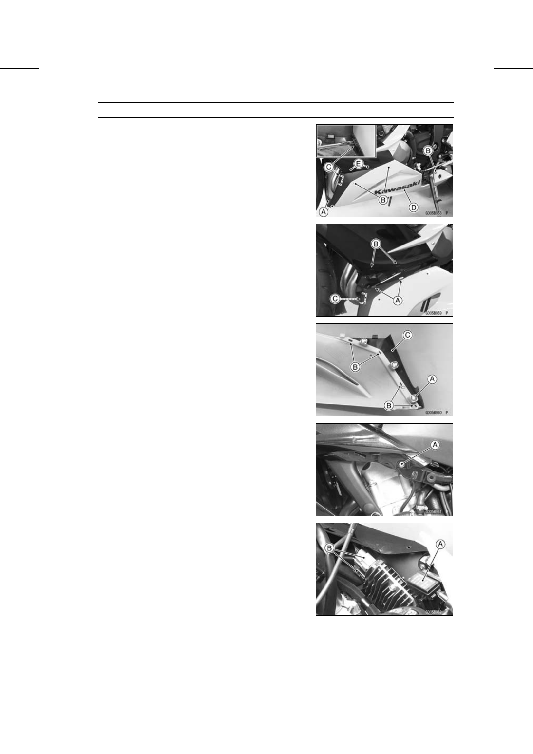
Lower Fairing Removal

Remove:

Quick Rivets [A]
Bolts and Washers [B]

Clear the hook [C] with the standard tip screwdriver.

Pull the lower fairing [D] outward to clear the hooks [E],
and remove the lower fairing.

Lower Fairing Installation

Insert the hooks [A] into the slots [B].

Hook the hook [C] to the middle fairing.

Install the bolts and washers.

Lower Fairing Disassembly

Remove the lower fairing (see Lower Fairing Removal).

Remove the screws [A].

Clear the hooks [B] and remove the lower fairing cover
[C].

Upper Fairing Assembly Removal

Remove:

Inner Cover (see Inner Cover Removal)
Side Cover (see Side Cover Removal)
Fairing Cover (see Fairing Cover Removal)
Lower Fairing (see Lower Fairing Removal)
Inner Fairing (see Inner Fairing Removal)
Windshield (see Windshield Removal)
Bolt [A] and Washer (Both Sides)

Remove the fuse box [A].

Disconnect the regulator/rectifier connectors [B].

15-10 FRAME

Fairings

Disconnect (Left Side):

Front Turn Signal Light Lead Connector [A]
Head Light Lead Connector [B]
City Light Lead Connector [C]

Disconnect (Right Side):

Front Turn Signal Light Lead Connector [A]
Head Light Lead Connector [B]
City Light Lead Connector [C]

Remove (Both Sides):

Bolts [A]
Rear View Mirror [B]

Remove the bolts [A].

Remove the upper fairing assembly [A] forward.

FRAME 15-11

Fairings

Upper Fairing Assembly Installation

Installation is the reverse of removal.

Run the hoses, leads and harness correctly (see Cable,
Wire, and Hose Routing section in the Appendix chapter).

Insert the coolant reserve tank overflow hose [A] to the
hole [B] of the middle fairing.

Middle Fairing Removal

Remove:

Upper Fairing Assembly (see Upper Fairing Assembly
Removal)
Headlight (see Headlight Removal/Installation in the
Electrical System chapter)
Screws [A]
Middle Fairing [B]

Middle Fairing Installation

Check that the pads are in place on the middle fairing.

Fit the pad [A] on the rib [B] for the fairing cover.

Align the pad [C] with the line [D] on the middle fairing.

Install the middle fairing so that the tabs [A] fit the slots
[B].

Install the screws.

Center Fairing Removal/Installation

Remove:

Upper Fairing Assembly (see Upper Fairing Assembly
Removal)
Headlight (see Headlight Removal/Installation in the
Electrical System chapter)
Screws [A]
Center Fairing [B]

When installing the center fairing, fit the tabs [C] to the
slots.

15-12 FRAME

Fairings

Inner Fairing Removal

Remove:

Clamps [A]
Quick Rivets [B]

Remove (Both Sides):

Quick Rivets [A]
Inner Fairing [B]

Inner Fairing Installation

Fit the hooks [A] of the inner fairings.

Insert the tab [B] into the rib [C] on the upper fairing.

Install the quick rivets and clamps.

Fairing Cover Removal

Remove:

Bolts [A] and Washer
Quick Rivet [B]

Clear the projection [C].

Pull the fairing cover [D] backward to clear the hook [E],
and remove the fairing cover.

Fairing Cover Installation

Insert the hook [A] into the slot [B].

Fit the tabs [C] and projection [D] to the slots [E] and hole
[F].

Install the quick rivet, bolt and washer.

FRAME 15-13

Side Covers

Inner Cover Removal

Remove:

Bolts [A] and Washers
Inner Cover [B]

Inner Cover Installation

Fit the hooks [A] on the side cover to the holes [B] on the
inner cover.

Install the bolts and washers.

Side Cover Removal

Remove the inner cover (see Inner Cover Removal).

Remove the wellnut [A].

Clear the projections [B] and hook fasteners [C].

Pull the side cover [D] backward to clear the hooks [E],
and remove the side cover.

Remove the right side cover in the same way.

Side Cover Installation

Check that the hook fasteners [A] are in place on the fuel
tank [B] and frame [C].

Fit the hook fastener to the corner [D] on the fuel tank.

Fit the hook fastener to the corner [E] on the fame.

Set the hook fastener parallel to the line [F] on the frame.

16 mm (0.6 in.) [G]
40 mm (1.6 in.) [H]
73 mm (2.9 in.) [I]
35 mm (1.4 in.) [J]
27 mm (1.1 in.) [K]

15-14 FRAME

Side Covers

Check that the pads [A] and hook fasteners [B] are in
place on the side cover.

Set the pad and hook fasteners to the convex [C] on the
side cover.

Fit the pad to the rim end [D].

Fit the pad to the corner [E] on the rib.

1 mm (0.04 in.) [F]
Detail Y [G]
Section X- X [H]

Insert the hooks [A] into the slots [B].

Insert the projections [C] into the holes [D], and fit the hook
fasteners.

Install the wellnut.

Tank Cover Removal

Remove the side cover (see Side Cover Removal).

Remove the bolt [A].

Clear the projection [B], and remove the tank cover [C].

FRAME 15-15

Side Covers

Tank Cover Installation

Check that the dampers [A] are in place on the side cover.

Insert the projection [B] into the hole [C].

Tighten the bolt.

15-16 FRAME

Seat Covers

Seat Cover Removal

Remove:

Seats (see Front/Rear Seat Removal)
Bolts [A]

Pull the front seat cover [B] backward to clear the hooks
[C], and remove the front seat cover.

Remove:

Quick Rivets [A]
Bolts [B]

Clear the exhaust butterfly valve cables from the hook [C]
on the seat cover.

Pull the seat covers [D] backward to clear the hooks [E],
and remove the side covers.

Seat Cover Installation

Insert the hooks [A] into the slots [B].

Install the bolts and quick rivets.

Hold the exhaust butterfly valve cables to the hook on the
seat cover.

Check that the pad [A] is in place on the front seat cover
[B].

Fit the pad to the rib [C] of the front seat cover.

Insert the hooks [A] on the front seat cover into the slots
[B].

Tighten the bolts.

FRAME 15-17

Fenders

Front Fender Removal

Remove the front wheel (see Front Wheel Removal).

Clear the brake hoses and wheel rotation sensor lead
from the clamps [A] (both sides).

Remove:

Bolts [B] and Washers (Both Sides)
Front Fender [C]

Front Fender Installation

Tighten:

Torque - Front Fender Mounting Bolts: 3.9 N·m (0.40 kgf·m,

35 in·lb)

Rear Fender Removal

Remove:

Fuel Tank (see Fuel Tank Removal in the Fuel System
(DFI) chapter)
Battery (see Battery Removal in the Electrical System
chapter)
Flap (see Flap Removal).

Pull the tail/brake light cover [A] backward to clear the
hooks [B], and remove the tail/brake light cover.

Remove:

Seat Lock Cover [A]
Seat Lock Cable [B]

Disconnect the starter motor cable [A] from the starter
relay [B].

15-18 FRAME

Fenders

Disconnect:

Vehicle-down Sensor Connector [A]
Tail/Brake Light Lead Connector [B]

Remove the clamps [C].

Remove:

Exhaust Butterfly Valve Actuator [A] (see Exhaust But-
terfly Valve Actuator Removal in the Fuel System (DFI)
chapter)
ECU (with Relay Box) [B]
Turn signal Relay [C]
Fuse Box [D]
Bolts [E]
Bolts and Nuts [F]
Pad [G]
Clamps [H]

Remove the rear fender backward.

Rear Fender Installation

Installation is the reverse of removal.

Run the cables, leads, harness and hoses correctly (see
Cable, Wire, and Hose Routing section in the Appendix
chapter).

Check that the pad [A] in place on the rear fender [B].

5 mm (0.20 in.) [C]

Insert the hooks [A] on the tail/brake light cover into the
slits [B] on the rear fender.

FRAME 15-19

Fenders

Flap Removal

Remove the seat cover (see Seat Cover Removal).

Disconnect:

Turn Signal Relay Lead Connectors [A]
License Plate Light Lead Connector [B]

Clear the lead from the clamp [C].

Remove:

Flap Mounting Bolts [A]
Clamp [B]
Flap

Flap Installation

Installation is the reverse of removal.

Run the cables, leads, harness and hoses correctly (see
Cable, Wire, and Hose Routing section in the Appendix
chapter).

Apply a non-permanent locking agent to the threads of
the flap mounting bolts.

15-20 FRAME

Frame

Rear Frame Rear Removal

Remove:

Rear Fender (see Rear Fender Removal)
Rear Frame Bolts (M8) [A] (Both Sides)
Rear Frame Rear [B]

Rear Frame Rear Installation

Check that the pads [A] are in place on the rear frame
rear.

Align the pads with the line [B] on the rear frame rear.

Apply a non-permanent locking agent to the threads of
the rear frame bolts (M8) and tighten them.

Torque - Rear Frame Bolts (M8): 25 N·m (2.5 kgf·m, 18 ft·lb)

Rear Frame Front Removal

Remove:

Rear Frame Rear (see Rear Frame Rear Removal)
Rear Footpeg Bracket Bolts [A] (Both Sides)
Muffler Body Mounting Bolts [B]
Rear Footpeg Brackets [C]
Rear Frame Bolt (M10) [D] (Both Sides)
Rear Frame Front [E]

Rear Frame Front Installation

Apply a non-permanent locking agent to the threads of
the rear frame bolts (M10) and tighten them.

Torque - Rear Frame Bolts (M10): 44 N·m (4.5 kgf·m, 32

ft·lb)

Rear Footpeg Bracket Bolts: 25 N·m (2.5 kgf·m, 18

ft·lb)

Muffler Body Mounting Bolt: 25 N·m (2.5 kgf·m, 18

ft·lb)

Frame Inspection

Visually inspect the frame for cracks, dents, bending, or
warp.
If there is any damage to the frame, replace it.

WARNING

A repaired frame may fail in use, possibly causing
an accident resulting in injury or death. If the frame
is bent, dented, cracked, or warped, replace it.

FRAME 15-21

Windshield

Windshield Removal

Remove:

Bolts with Washers [A]
Windshield [B]

Windshield Installation

Be sure that the wellnuts [A] are in position on the wind-
shield.

Tighten:

Torque - Windshield Mounting Bolts:

0.42 N·m (0.043

kgf·m, 3.7 in·lb)

15-22 FRAME

Guard

Mud Guard Removal

Remove:

Mud Guard Mounting Bolts [A]
Brake Hose Clamp [B]
Mud Guard [C]

Mud Guard Installation

Installation is the reverse of removal.

Apply a non-permanent locking agent to the threads of the
mud guard mounting bolts, and tighten them securely.

FRAME 15-23

Sidestand

Sidestand Removal

Raise the rear wheel off the ground with the stand [A].

Remove:

Sidestand Switch Bolt [A]
Sidestand Switch [B]

Remove:

Spring [A]
Sidestand Nut [B]
Sidestand Bolt [C]
Sidestand [D]

Sidestand Installation

Apply grease to the sliding area [A] of the sidestand [B].

Replace the sidestand nut [C] with a new one.

Tighten the sidestand bolt [D], and then lock it with the
sidestand nut.

Torque - Sidestand Bolt: 29 N·m (3.0 kgf·m, 21 ft·lb)

Sidestand Nut: 44 N·m (4.5 kgf·m, 32 ft·lb)

Hook the spring [E] so that the long spring end faces up-
ward.

Install the spring hook direction as shown.

Install the sidestand switch [F].

Apply a non-permanent locking agent to the threads of
the sidestand switch bolt [G], and tighten it.

Torque - Sidestand Switch Bolt: 8.8 N·m (0.90 kgf·m, 78

in·lb)

ELECTRICAL SYSTEM 16-1

16

Electrical System

Table of Contents

Exploded View........................................................................................................................

16-3

Specifications .........................................................................................................................

16-10

Special Tools and Sealant ......................................................................................................

16-11

Parts Location.........................................................................................................................

16-13

Wiring Diagram (US, CA and CAL Models)............................................................................

16-16

Wiring Diagram (Other than US, CA and CAL Models)..........................................................

16-18

Wiring Diagram (KIBS Equipped Models: US, CA and CAL Models) ....................................

16-20

Wiring Diagram (KIBS Equipped Models: Other than US, CA and CAL Models) ..................

16-22

Precautions.............................................................................................................................

16-24

Electrical Wiring......................................................................................................................

16-25

Wiring Inspection ..............................................................................................................

16-25

Battery ....................................................................................................................................

16-26

Battery Removal ...............................................................................................................

16-26

Battery Installation ............................................................................................................

16-26

Battery Activation ..............................................................................................................

16-27

Precautions .......................................................................................................................

16-29

Interchange .......................................................................................................................

16-30

Charging Condition Inspection..........................................................................................

16-30

Refreshing Charge............................................................................................................

16-30

Charging System ....................................................................................................................

16-32

Alternator Cover Removal.................................................................................................

16-32

Alternator Cover Installation..............................................................................................

16-32

Stator Coil Removal ..........................................................................................................

16-32

Stator Coil Installation .......................................................................................................

16-33

Alternator Rotor Removal .................................................................................................

16-33

Alternator Rotor Installation ..............................................................................................

16-33

Charging Voltage Inspection .............................................................................................

16-35

Alternator Inspection .........................................................................................................

16-35

Regulator/Rectifier Inspection...........................................................................................

16-37

Ignition System .......................................................................................................................

16-39

Crankshaft Sensor Removal .............................................................................................

16-39

Crankshaft Sensor Installation ..........................................................................................

16-39

Crankshaft Sensor Inspection...........................................................................................

16-40

Crankshaft Sensor Peak Voltage Inspection.....................................................................

16-40

Stick Coil Removal............................................................................................................

16-41

Stick Coil Installation.........................................................................................................

16-41

Stick Coil Inspection..........................................................................................................

16-41

Stick Coil Primary Peak Voltage Inspection ......................................................................

16-42

Spark Plug Removal .........................................................................................................

16-42

Spark Plug Installation ......................................................................................................

16-42

Spark Plug Condition Inspection.......................................................................................

16-43

Interlock Operation Inspection ..........................................................................................

16-43

IC Igniter Inspection ..........................................................................................................

16-44

Electric Starter System ...........................................................................................................

16-47

Starter Motor Removal......................................................................................................

16-47

Starter Motor Installation...................................................................................................

16-47

Starter Motor Disassembly................................................................................................

16-48

Starter Motor Assembly ....................................................................................................

16-48

Brush Inspection ...............................................................................................................

16-49

Commutator Cleaning and Inspection...............................................................................

16-50

16-2 ELECTRICAL SYSTEM

Armature Inspection..........................................................................................................

16-50

Brush Lead Inspection ......................................................................................................

16-50

Left-hand End Cover Assembly Inspection.......................................................................

16-51

Starter Relay Inspection....................................................................................................

16-51

Lighting System ......................................................................................................................

16-53

Headlight Beam Horizontal Adjustment ............................................................................

16-53

Headlight Beam Vertical Adjustment.................................................................................

16-53

Headlight Bulb Replacement ............................................................................................

16-53

City Light Bulb Replacement.............................................................................................

16-54

Headlight Removal/Installation .........................................................................................

16-54

Tail/Brake Light (LED) Removal/Installation......................................................................

16-55

License Plate Light Bulb Replacement .............................................................................

16-55

Turn Signal Light Bulb Replacement ................................................................................

16-57

Turn Signal Relay Inspection ............................................................................................

16-59

Air Switching Valve .................................................................................................................

16-61

Air Switching Valve Operation Test ...................................................................................

16-61

Air Switching Valve Unit Test ............................................................................................

16-61

Radiator Fan System..............................................................................................................

16-63

Fan Motor Inspection ........................................................................................................

16-63

Meter, Gauge, Indicator Unit...................................................................................................

16-64

Meter Unit Removal/Installation ........................................................................................

16-64

Meter Unit Disassembly ....................................................................................................

16-64

Meter Operation Inspection...............................................................................................

16-65

Meter System Inspection ..................................................................................................

16-68

Meter Unit Inspection ........................................................................................................

16-69

Immobilizer System (Equipped Models) .................................................................................

16-74

Operational Cautions ........................................................................................................

16-74

Key Registration................................................................................................................

16-74

Immobilizer System Parts Replacement ...........................................................................

16-92

Immobilizer System Inspection .........................................................................................

16-93

Immobilizer System (Equipped Models) .................................................................................

16-94

Switches and Sensors ............................................................................................................

16-95

Brake Light Timing Inspection...........................................................................................

16-95

Brake Light Timing Adjustment .........................................................................................

16-95

Switch Inspection ..............................................................................................................

16-95

Water Temperature Sensor Inspection .............................................................................

16-96

Fuel Reserve Switch Inspection........................................................................................

16-96

Oxygen Sensor Removal (Equipped Models)...................................................................

16-97

Oxygen Sensor Installation (Equipped Models)................................................................

16-97

Oxygen Sensor Inspection (Equipped Models).................................................................

16-97

Oxygen Sensor Heater Inspection (Equipped Models).....................................................

16-98

Gear Position Switch Removal .........................................................................................

16-98

Gear Position Switch Installation ......................................................................................

16-99

Gear Position Switch Inspection .......................................................................................

16-99

Relay Box ............................................................................................................................... 16-101

Relay Box Removal .......................................................................................................... 16-101
Relay Circuit Inspection 
.................................................................................................... 16-101
Diode Circuit Inspection 
.................................................................................................... 16-102

Fuse........................................................................................................................................ 16-103

30 A Main/15 A ECU Fuse Removal................................................................................. 16-103
Fuse Box Fuse Removal..................
................................................................................. 16-103
Fuse Installation
................................................................................................................ 16-103
Fuse Inspection..
............................................................................................................... 16-104

ELECTRICAL SYSTEM 16-3

Exploded View

This page intentionally left blank.

16-4 ELECTRICAL SYSTEM

Exploded View

ELECTRICAL SYSTEM 16-5

Exploded View

Torque

No.

Fastener

N·m

kgf·m

ft·lb

Remarks

1

Front Turn Signal Light Mounting Screw

1.2

0.12

11 in·lb

2

Meter Unit Mounting Screws

1.2

0.12

11 in·lb

3

License Plate Light Mounting Nuts

3.5

0.36

31 in·lb

4

License Plate Light Cover Screws

1.0

0.10

8.9 in·lb

16-6 ELECTRICAL SYSTEM

Exploded View

ELECTRICAL SYSTEM 16-7

Exploded View

Torque

No.

Fastener

N·m

kgf·m

ft·lb

Remarks

1

Left Switch Housing Screws

3.5

0.36

31 in·lb

2

Right Switch Housing Screws

3.5

0.36

31 in·lb

3

Front Brake Light Switch Screw

1.2

0.12

11 in·lb

4

Crankshaft Sensor Bolts

5.9

0.60

52 in·lb

5

Starter Clutch Cover Bolts (L = 30 mm)

9.8

1.0

87 in·lb

6

Starter Clutch Cover Bolt (L = 20 mm)

9.8

1.0

87 in·lb

7

Starter Clutch Bolt Cap

2.9

0.30

26 in·lb

8

Oil Pressure Switch

15

1.5

11

SS

9

Oil Pressure Switch Terminal Bolt

1.5

0.15

13 in·lb

G

10

Starter Motor Mounting Bolts

9.8

1.0

87 in·lb

11

Alternator Rotor Bolt

155

15.8

114

12

Stator Coil Bolts

12

1.2

106 in·lb

L

13

Alternator Lead Holding Plate Bolt

9.8

1.0

87 in·lb

L

14

Alternator Cover Bolts

9.8

1.0

87 in·lb

15. Immobilizer System Equipped Models

G: Apply grease.

L: Apply a non-permanent locking agent.

M: Apply molybdenum disulfide grease.

MO: Apply molybdenum disulfide oil solution.

(mixture of the engine oil and molybdenum disulfide grease in a weight ratio 10:1)

R: Replacement Parts

SS: Apply silicone sealant.

16-8 ELECTRICAL SYSTEM

Exploded View

ELECTRICAL SYSTEM 16-9

Exploded View

Torque

No.

Fastener

N·m

kgf·m

ft·lb

Remarks

1

Regulator/Rectifier Bracket Screws

1.2

0.12

11 in·lb

2

Spark Plugs

13

1.3

115 in·lb

3

Gear Position Switch Screws

2.9

0.30

26 in·lb

L

4

Water Temperature Sensor

12

1.2

106 in·lb

5

Starter Motor Cable Terminal Bolt

2.9

0.30

26 in·lb

6

Fuel Pump Bolts

9.8

1.0

87 in·lb

L, S

7

Engine Ground Cable Terminal Bolt

9.8

1.0

87 in·lb

8

Sidestand Switch Bolt

8.8

0.90

78 in·lb

L

9

Oxygen Sensor (Equipped Models)

25

2.5

18

G: Apply grease.

L: Apply a non-permanent locking agent.

R: Replacement Parts

S: Follow the specified tightening sequence.

16-10 ELECTRICAL SYSTEM

Specifications

Item

Standard

Battery

Type

Sealed Battery

Model Name

YTX9-BS

Capacity

12 V 8 Ah

Voltage

12.8 V or more

Gross Weight

2.9 kg (6.4 lb)

Electrolyte Volume

0.40 L (24 cu in.)

Charging System

Type

Three-phase AC

Alternator Output Voltage

46.4 V or more at 4 000 r/min (rpm)

Stator Coil Resistance

0.11

0.17

at 20°C (68°F)

Charging Voltage (Regulator/Rectifier
Output Voltage)

14.3

14.7 V

Ignition System

Crankshaft Sensor:

Resistance

368

552

Peak Voltage

2.6 V or more

Stick Coil:

Primary Winding Resistance

0.85

1.15

Secondary Winding Resistance

5.0

6.8 k

Primary Peak Voltage

120 V or more

Spark Plug:

Type

NGK CR9E

Gap

0.7

0.8 mm (0.028

0.031 in.)

Electric Starter System

Starter Motor:

Brush Length

7 mm (0.28 in.) (Service Limit: 5 mm (0.20 in.))

Commutator Diameter

24 mm (0.94 in.) (Service Limit: 23 mm (0.91 in.))

Air Switching Valve

Resistance

20

24

at 20°C (68°F)

Meter Unit

CAN Communication Line Resistance

122

126

at meter connector

Switches and Sensors

Rear Brake Light Switch Timing

ON after about 10 mm (0.39 in.) of pedal travel

Oil Pressure Switch Connections

When engine is stopped: ON

When engine is running: OFF

Water Temperature Sensor Resistance

in the text

Gear Position Switch Resistance

in the text

ELECTRICAL SYSTEM 16-11

Special Tools and Sealant

Hand Tester:
57001-1394

Flywheel Puller Assembly, M38 × 1.5/M35 × 1.5:
57001-1405

Peak Voltage Adapter:
57001-1415

Lead Wire - Peak Voltage Adapter:
57001-1449

Key Registration Unit:
57001-1582

Grip:
57001-1591

Rotor Holder:
57001-1666

Stopper:
57001-1679

Rotor Holder Attachment:
57001-1689

Key Registration Adapter:
57001-1746

16-12 ELECTRICAL SYSTEM

Special Tools and Sealant

Liquid Gasket, TB1211F:
92104-0004

ELECTRICAL SYSTEM 16-13

Parts Location

This page intentionally left blank.

16-14 ELECTRICAL SYSTEM

Parts Location

ELECTRICAL SYSTEM 16-15

Parts Location

1. Immobilizer Amplifier (Equipped Models)
2. Ignition Switch

(Immobilizer Equipped Models: Including Immobilizer Antenna)

3. Starter Lockout Switch
4. Starter Relay
5. Battery 12 V 8 Ah
6. ECU
7. Relay Box
8. Turn Signal Relay
9. Gear Position Switch

10. Sidestand Switch

11. Alternator

12. Fan Motor
13. Water Temperature Sensor
14. Starter Motor
15. Stick Coils
16. Air Switching Valve
17. Meter Unit
18. Front Brake Light Switch
19. Spark Plugs
20. Crankshaft Sensor
21. Oil Pressure Switch
22. Oxygen Sensor (Equipped Models)
23. Rear Brake Light Switch
24. Fuel Reserve Switch
25. Fuel Pump
26. Fuse Box 1
27. Fuse Box 2
28. Regulator/Rectifier

16-16 ELECTRICAL SYSTEM

Wiring Diagram (US, CA and CAL Models)


Content      ..     14      15      16      17     ..