Kawasaki Motorcycle Ninja ZX-6R / Ninja ZX-6R ABS. Service Manual (2013 year) - page 14
 

  Index      Manuals     Kawasaki Motorcycle Ninja ZX-6R / Ninja ZX-6R ABS. Service Manual (2013 year)


Search            copyright infringement  


Content      ..     12      13      14      15     ..


Kawasaki Motorcycle Ninja ZX-6R / Ninja ZX-6R ABS. Service Manual (2013 year) - page 14


BRAKES 12-45

KIBS (Equipped Models)

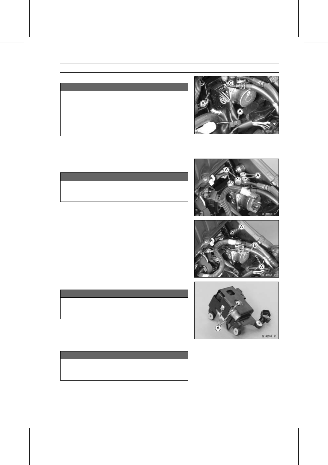
Clean the KIBS hydraulic unit.

NOTICE

Clean all fittings on the KIBS hydraulic unit and the
rear master cylinder because dirt around the banjo
bolts could contaminate the brake fluid in the line
during removal/installation.
Spread over a shop towel around the KIBS hy-
draulic unit before removing the brake line so that
brake fluid does not leak on the parts.

Open the clamp [A].

Pull the lever [B] backward to disconnect the KIBS hy-
draulic unit connector [C].

Remove:

Brake Pipe Banjo Bolts [A]

NOTICE

Brake fluid quickly ruins painted plastic surfaces;
any spilled fluid should be completely washed away
immediately.

Remove the bolts [A].

Remove the KIBS hydraulic unit [B] together with the
bracket.

Clear the bracket from the KIBS hydraulic unit rubber
cover.

Remove the bolts [A] and bracket.

NOTICE

The KIBS hydraulic unit has been adjusted and set
with precision at the factory. Do not try to disas-
semble and repair the KIBS hydraulic unit.

KIBS Hydraulic Unit Installation

NOTICE

Brake fluid quickly ruins painted plastic surfaces;
any spilled fluid should be completely washed away
immediately.

12-46 BRAKES

KIBS (Equipped Models)

Install the KIBS hydraulic unit together with the bracket,
and tighten the bolts.

Fit the bracket and KIBS hydraulic unit rubber cover (see
Cable, Wire, and Hose Routing section in the Appendix
chapter).

Replace the washers that are on each side of pipe fitting
with new ones.

Install the brake pipes (see Cable, Wire, and Hose Rout-
ing section in the Appendix chapter).

Tighten:

Torque - Brake Pipe Banjo Bolts: 23 N·m (2.3 kgf·m, 17 ft·lb)

Pull the lever [A] forward to connect the KIBS hydraulic
unit connector [B].

Bleed the brake line (see Brake Line Bleeding).

Check the brake for good braking power, no brake drag,
and no fluid leakage.

Install the fuel tank (see Fuel Tank Installation in the Fuel
System (DFI) chapter).

KIBS Hydraulic Unit Inspection

Remove the KIBS hydraulic unit (see KIBS Hydraulic Unit
Removal).

Visually inspect the connector terminals [A].
Replace the KIBS hydraulic unit or main harness if either
of the terminals are cracked, bent, or otherwise damaged.
If the KIBS hydraulic unit connector is clogged with mud
or dust, blow it off with compressed air.

Visually inspect the KIBS hydraulic unit.
Replace the KIBS hydraulic unit if any of them are
cracked, or otherwise damaged.

Front Wheel Rotation Sensor Removal

NOTICE

The wheel rotation sensor should be handled care-
fully, never struck sharply, as with a hammer, or al-
lowed to fall on a hard surface since the wheel rota-
tion sensor is precision made. Be careful not to get
water or mud on the wheel rotation sensor.
Do not try to disassemble or repair the wheel rota-
tion sensor.

BRAKES 12-47

KIBS (Equipped Models)

Remove:

Air Cleaner Housing (see Air Cleaner Housing Removal
in the Fuel System (DFI) chapter)

Slide the dust cover [A].

Open the clamp [B].

Disconnect the front wheel rotation sensor lead connector
[C].

Clear the sensor lead from the clamps [A].

Remove:

Bolt [B]
Front Wheel Rotation Sensor [C]

Front Wheel Rotation Sensor Installation

Installation is the reverse of removal.

Run the lead correctly (see Cable, Wire, and Hose Rout-
ing section in the Appendix chapter).

Rear Wheel Rotation Sensor Removal

NOTICE

The wheel rotation sensor should be handled care-
fully, never struck sharply, as with a hammer, or al-
lowed to fall on a hard surface since the wheel rota-
tion sensor is precision made. Be careful not to get
water or mud on the wheel rotation sensor.
Do not try to disassemble or repair the wheel rota-
tion sensor.

12-48 BRAKES

KIBS (Equipped Models)

Remove:

Fuel Tank (see Fuel Tank Removal in the Fuel System
(DFI) chapter)

Slide the dust cover [A].

Disconnect the rear wheel rotation sensor lead connector
[B].

Clear the sensor lead from the clamps [A].

Clear the sensor lead from the clamps [A].

Remove:

Bolt [B]
Rear Wheel Rotation Sensor [C]

Rear Wheel Rotation Sensor Installation

Installation is the reverse of removal.

Route the lead correctly (see Cable, Wire, and Hose
Routing section in the Appendix chapter).

Wheel Rotation Sensor Inspection

Remove the front wheel rotation sensor [A] from the front
fork.

Remove the rear wheel rotation sensor [B] from the
caliper bracket.

Visually inspect the wheel rotation sensors.
Replace the wheel rotation sensor if it is cracked, bent, or
otherwise damaged.

BRAKES 12-49

KIBS (Equipped Models)

Wheel Rotation Sensor Air Gap Inspection

Raise the front/rear wheel off the ground (see Front/Rear
Wheel Removal in the Wheels/Tires chapter).

Measure the air gap between the sensor and sensor rotor
at several points by turning the wheel slowly.

Thickness Gauge [A]

Wheel Rotation Sensor Air Gap

Standard:

Front

0.4

1.6 mm (0.02

0.06 in.)

Rear

0.4

1.6 mm (0.02

0.06 in.)

NOTE

The sensor air gap cannot be adjusted.

If the air gap is not within the specification, inspect the hub
bearing (see Hub Bearing Inspection in the Wheels/Tires
chapter), sensor installation condition and sensor (see
Wheel Rotation Sensor Inspection).

Wheel Rotation Sensor Rotor Inspection

Remove:

Wheels (see Front/Rear Wheel Removal in the
Wheels/Tires chapter)
Brake Disc Mounting Bolts [A]
Sensor Rotor [B]
Front Wheel [C]
Rear Wheel [D]

12-50 BRAKES

KIBS (Equipped Models)

Visually inspect the wheel rotation sensor rotor.
If the rotor is deformed or damaged (chipped teeth [A]),
replace the sensor rotor with a new one.
If there is iron or other magnetic deposits [B], remove the
deposits.

Install:

Front Brake Disc [A]
Front Wheel Rotation Sensor Rotor [B]
Rear Brake Disc [C]
Rear Wheel Rotation Sensor Rotor [D]

When installing the rear wheel rotation sensor rotor, the
bended end [E] faces to disc side.

Install the brake discs (see Brake Disc Installation).

KIBS Solenoid Valve Relay Fuse (15 A) Removal

Refer to the Fuse Box Fuse Removal in the Electrical Sys-
tem chapter.

KIBS Motor Relay Fuse (25 A) Removal

Refer to the Fuse Box Fuse Removal in the Electrical Sys-
tem chapter.

Fuse Installation

If a fuse fails during operation, inspect the electrical sys-
tem to determine the cause, and then replace it with a
new fuse of proper amperage (see Fuse Installation in the
Electrical System chapter).

Fuse Inspection

Remove the fuses (see KIBS Solenoid Valve Relay Fuse
(15 A)/KIBS Motor Relay Fuse (25 A) Removal).

Refer to the Fuse Inspection in the Electrical System
chapter.

SUSPENSION 13-1

13

Suspension

Table of Contents

Exploded View........................................................................................................................

13-2

Specifications .........................................................................................................................

13-6

Special Tools ..........................................................................................................................

13-7

Front Fork ...............................................................................................................................

13-9

Rebound Damping Force Adjustment...............................................................................

13-9

Compression Damping Force Adjustment ........................................................................

13-9

Spring Preload Adjustment ...............................................................................................

13-10

Front Fork Removal (Each Fork Leg) ...............................................................................

13-10

Front Fork Installation (Each Fork Leg) ............................................................................

13-11

Front Fork Oil Change ......................................................................................................

13-12

Front Fork Disassembly ....................................................................................................

13-20

Front Fork Assembly.........................................................................................................

13-20

Inner Tube Inspection .......................................................................................................

13-21

Dust Seal Inspection .........................................................................................................

13-21

Spring Tension Inspection.................................................................................................

13-22

Rear Shock Absorber .............................................................................................................

13-23

Rebound Damping Force Adjustment...............................................................................

13-23

Compression Damping Force Adjustment ........................................................................

13-23

Spring Preload Adjustment ...............................................................................................

13-23

Rear Shock Absorber Removal ........................................................................................

13-24

Rear Shock Absorber Installation .....................................................................................

13-25

Rear Shock Absorber Inspection ......................................................................................

13-25

Rear Shock Absorber Scrapping ......................................................................................

13-26

Swingarm................................................................................................................................

13-27

Swingarm Removal...........................................................................................................

13-27

Swingarm Installation........................................................................................................

13-27

Swingarm Bearing Removal .............................................................................................

13-28

Swingarm Bearing Installation ..........................................................................................

13-29

Swingarm Bearing, Sleeve Inspection ..............................................................................

13-30

Swingarm Bearing Lubrication ..........................................................................................

13-30

Tie-Rod, Rocker Arm ..............................................................................................................

13-31

Tie-Rod Removal ..............................................................................................................

13-31

Tie-Rod Installation ...........................................................................................................

13-31

Rocker Arm Removal........................................................................................................

13-31

Rocker Arm Installation.....................................................................................................

13-32

Tie-Rod and Rocker Arm Bearing Removal......................................................................

13-33

Tie-Rod and Rocker Arm Bearing Installation...................................................................

13-33

Rocker Arm/Tie-Rod Bearing, Sleeve Inspection .............................................................

13-35

Rocker Arm/Tie-Rod Bearing Lubrication .........................................................................

13-35

13-2 SUSPENSION

Exploded View

SUSPENSION 13-3

Exploded View

Torque

No.

Fastener

N·m

kgf·m

ft·lb

Remarks

1

Upper Front Fork Clamp Bolts

20

2.0

15

2

Lower Front Fork Clamp Bolts

23

2.3

17

AL

3

Front Fork Top Plugs

35

3.6

26

4

Piston Rod Guide Case

90

9.2

66

5

Front Axle Clamp Bolts

20

2.0

15

AL

AL: Tighten the two clamp bolts alternately two times to ensure even tightening torque.

G: Apply grease.

R: Replacement Parts

13-4 SUSPENSION

Exploded View

SUSPENSION 13-5

Exploded View

Torque

No.

Fastener

N·m

kgf·m

ft·lb

Remarks

1

Rear Shock Absorber Bracket Nut

59

6.0

44

2

Swingarm Pivot Shaft Nut

108

11.0

79.7

3

Swingarm Pivot Shaft

20

2.0

15

4

Swingarm Pivot Adjusting Collar Locknut

98

10.0

72

5

Upper Rear Shock Absorber Nut

34

3.5

25

R

6

Rocker Arm Bolt

34

3.5

25

7

Lower Rear Shock Absorber Nut

34

3.5

25

R

8

Tie-Rod Nuts

59

6.0

44

R

G: Apply grease.

R: Replacement Parts

13-6 SUSPENSION

Specifications

Item

Standard

Front Fork (Per One Unit)

Fork Inner Tube Diameter

41 mm (1.6 in.)

Air Pressure

Atmospheric pressure (Non-adjustable)

Rebound Damper Setting

4 1/2 turns out from the fully clockwise position

(Usable Range: 0

←→

5 1/2 turns out)

Compression Damper Setting

6 turns out from the fully clockwise position

(Usable Range: 0

←→

7 turns out)

Fork Spring Preload Setting

5 turns in from the fully counterclockwise position

(Usable Range: 0

←→

20 turns in)

Fork Oil:

Recommended Oil

SHOWA SS-47 or equivalent

Amount:

Right Front Fork

Approx. 460 mL (15.6 US oz.) (when changing oil)

538 ±2.5 mL (18.2 ±0.085 US oz.) (after disassembly and
completely dry)

Left Front Fork

Approx. 480 mL (16.2 US oz.) (when changing oil)

566 ±2.5 mL (19.1 ±0.085 US oz.) (after disassembly and
completely dry)

Oil Level:

Right Front Fork

90 ±2 mm (3.54 ±0.08 in.) (fully compressed, below from
the top of outer tube)

Left Front Fork

80 ±2 mm (3.15 ±0.08 in.) (fully compressed, below from
the top of outer tube)

Fork Spring Free Length

256 mm (10.08 in.) (Service Limit: 251 mm (9.88 in.))

Rear Shock Absorber

Rebound Damper Setting

1 1/2 turns out from the fully clockwise position

(Usable Range: 0

←→

3 turns out)

Compression Damper Setting

2 1/2 turns out from the fully clockwise position
(Usable Range: 0

←→

5 turns out)

Spring Preload Setting Position:

Standard

Spring length: 205 mm (8.07 in.)

Usable Range

Spring length: 199

209 mm (7.83

8.23 in.) (stronger to

weaker)

Gas Pressure

980 kPa (10.0 kgf/cm², 142 psi, Non-adjustable)

SUSPENSION 13-7

Special Tools

Inside Circlip Pliers:
57001-143

Oil Seal & Bearing Remover:
57001-1058

Bearing Driver Set:
57001-1129

Jack:
57001-1238

Fork Oil Seal Driver,

41:

57001-1288

Fork Oil Level Gauge:
57001-1290

Hook Wrench T=3.2 R37:
57001-1539

Swingarm Pivot Nut Wrench:
57001-1597

Jack Attachment:
57001-1608

Needle Bearing Driver,

17/ 18:

57001-1609

13-8 SUSPENSION

Special Tools

Needle Bearing Driver,

28:

57001-1610

Spacer,

18:

57001-1636

Spacer,

28:

57001-1637

Hook Wrench:
57001-1641

Needle Bearing Driver,

20 & Spacer,

28:

57001-1678

Top Plug Wrench (45 mm):
57001-1741

Rod Guide Case Wrench, 33 mm:
57001-1744

SUSPENSION 13-9

Front Fork

Rebound Damping Force Adjustment

To adjust the rebound damping force, turn the rebound
damping adjuster [A].

The standard adjuster setting is the

4 1/2 turns out

from

the fully clockwise position.

The damping force can be left soft for average riding. But
it should be adjusted harder for high speed riding or riding
with a passenger. If the damping feels too soft or too stiff,
adjust it in accordance with the following table.

Rebound Damping Force Adjustment

Adjuster

Position

Damping

Force

Setting

Load

Road

Speed

5 1/2

turns out

Weak

Soft

Light

Good

Low

0

Strong

Hard

Heavy

Bad

High

Compression Damping Force Adjustment

To adjust the compression damping force, turn the com-
pression damping adjuster [A].

The standard adjuster setting is the

6 turns out

from the

fully clockwise position.

The damping force can be left soft for average riding. But
it should be adjusted harder for high speed riding or riding
with a passenger. If the damping feels too soft or too stiff,
adjust it in accordance with the following table.

Compression Damping Force Adjustment

Adjuster

Position

Damping

Force

Setting

Load

Road

Speed

7 turns out

Weak

Soft

Light

Good

Low

0

Strong

Hard

Heavy

Bad

High

13-10 SUSPENSION

Front Fork

Spring Preload Adjustment

To adjust the spring preload, turn the spring preload ad-
juster [A].

The standard adjuster setting is the

5 turns in

from the

fully counterclockwise position.

The spring preload can be left soft for average riding. But
it should be adjusted harder for high speed riding or riding
with a passenger. If the spring action feels too soft or too
stiff, adjust it in accordance with the following table.

Spring Action

Adjuster

Position

Damping

Force

Setting

Load

Road

Speed

0

Weak

Soft

Light

Good

Low

20 turns in

Strong

Hard

Heavy

Bad

High

Front Fork Removal (Each Fork Leg)

Remove:

Front Wheel (see Front Wheel Removal in the
Wheels/Tires chapter)
Front Fender (see Front Fender Removal in the Frame
chapter)
Inner Fairing (see Inner Fairing Removal in the Frame
chapter)

Loosen the front fork top plug [A] beforehand if the fork
leg is to be disassembled.

Special Tool - Top Plug Wrench (45 mm): 57001-1741 [B]

NOTE

Loosen the top plug after loosening the handlebar
clamp bolt [C] and upper front fork clamp bolt [D].

Loosen:

Handlebar Clamp Bolt [A]
Upper Front Fork Clamp Bolt [B]
Lower Front Fork Clamp Bolts [C]

With a twisting motion, work the fork leg down and out.

SUSPENSION 13-11

Front Fork

Front Fork Installation (Each Fork Leg)

Install the fork so that the top end [A] of the outer tube as
shown.

7 mm (0.28 in.) [B]
Steering Stem Head [C]

Tighten:

Torque - Lower Front Fork Clamp Bolts: 23 N·m (2.3 kgf·m,

17 ft·lb)

NOTE

Tighten the two lower front fork clamp bolts alternately
two times to ensure even tightening torque.

Torque - Front Fork Top Plugs: 35 N·m (3.6 kgf·m, 26 ft·lb)

NOTE

Tighten the front fork top plug [A] before tightening the
handlebar clamp bolt and upper front fork clamp bolt.

The torque of front fork top plug is specified to 35 N·m
(3.6 kgf·m, 26 ft·lb) however, when you use the top
plug wrench (special tool: 57001-1741) [B], reduce the
torque to 90% of the specified value [31 N·m (3.2 kgf·m,
23 ft·lb)] due to the distance [C] between the center of
the square hole, where the torque wrench [D] is fitted,
and that of the octagonal hole of the wrench.

This torque value [31 N·m (3.2 kgf·m, 23 ft·lb)] is ap-
plicable when you use a torque wrench whose length
gives leverage of approximately 310 mm (12.2 in.) be-
tween the grip point to the center of the coupling square.

To obtain the correct tightening torque with your torque
wrench, you need to calculate as follows.

Formula:

a × b ÷ (b + c) = d

[a] Specified torque
[b] Length from center of square hole to grip point
[c] Offset = 44 mm
[d] Tightening torque

For an example:

35 N·m ×310 ÷ (310 + 44) = 31 N·m

Tighten:

Torque - Upper Front Fork Clamp Bolts: 20 N·m (2.0 kgf·m,

15 ft·lb)

Handlebar Clamp Bolts: 25 N·m (2.5 kgf·m, 18

ft·lb)

Install the removed parts (see appropriate chapters).

Adjust:

Spring Preload (see Spring Preload Adjustment)
Rebound Damping Force (see Rebound Damping Force
Adjustment)
Compression Damping Force (see Compression Damp-
ing Force Adjustment)

13-12 SUSPENSION

Front Fork

Front Fork Oil Change

Right Front Fork

Remove the front fork (see Front Fork Removal (Each
Fork Leg)).

Hold the inner tube lower end in a vise.

Using the wrench [A], unscrew the top plug [B] out of the
outer tube.

Special Tool - Top Plug Wrench (45 mm): 57001-1741

Holding the piston rod nut with a wrench [A], remove the
top plug [B] from the piston rod.

Special Tool - Top Plug Wrench (45 mm): 57001-1741

Remove:

Rebound Damping Adjuster Rod (Inside) [A]
Compression Damping Adjuster Rod (Outside) [B]
Piston Rod Nut [C]

Using the rod guide case wrench [A], remove the piston
rod guide case from the inner tube.

Special Tool - Rod Guide Case Wrench, 33 mm: 57001

-1744

NOTICE

A socket of piston rod guide case is shallow (4 mm)
and therefore be sure to check that the wrench
(Special Tool: 57001-1744) is securely seated on
the piston rod guide case.
When loosening the piston rod guide case. If the
wrench is not securely seated on it, the piston rod
guide case may brake.

SUSPENSION 13-13

Front Fork

Remove:

Piston Rod Assy [A]
Collar [B]
Fork Spring [C]

Drain the fork oil into a suitable container [A].

Pump the inner tube up and down at least 10 times to
expel the oil from the fork.

Install:

Fork Spring [A]

Install the collar [B] so that the large diameter side faces
downward.

Hold the fork tube upright, press the outer tube.

Pour in the type and amount of fork oil specified.

Pour the fork oil until the upper of the inner tube hole [A].

Suspension Oil - SHOWA SS-47: 44091-0010

Amount:

When changing oil:

Approx. 460 mL (15.6 US oz.)

After disassembly and completely dry:

538 ±2.5 mL (18.2 ±0.085 US oz.)

Move the inner tube up and down more than 10 times in
order to expel the air from the fork oil.

Install the piston rod assy and piston rod guide case into
the inner tube.

NOTE

Lifting the outer tube, and install the piston rod guide
case.

NOTICE

When inserting, be careful not to damage the piston
ring [A].

13-14 SUSPENSION

Front Fork

Hold the inner tube bottom by a vise.

Using the rod guide case wrench [A], tighten the piston
rod guide case to the inner tube.

Special Tool - Rod Guide Case Wrench, 33 mm: 57001

-1744

Torque - Piston Rod Guide Case: 90 N·m (9.2 kgf·m, 66 ft·lb)

NOTE

The tightening torque of the piston rod guide case is
specified to 90 N·m (9.2 kgf·m, 66 ft·lb), however in use
of the rod guide case wrench (special tool: 57001-1744)
[A] you reduce the torque to about 90% of the specified
value [81 N·m (8.3 kgf·m, 60 ft·lb)] due to the offset [B]
of the wrench square hole.

This torque value [81 N·m (8.3 kgf·m, 60 ft·lb)] is appli-
cable when you use a wrench whose length [C] gives
leverage of approximately 450 mm (17.7 in.) between
the grip point [D] to the center of the coupling square.

To obtain the correct tightening torque with your torque
wrench, you need to calculate as follows.

Formula:

a × b ÷ (b + c) = d

[a] Specified torque
[b] Length from center of square hole to grip point
[c] Offset = 50 mm
[d] Tightening torque

For an example:

90 N·m × 450 ÷ (450 + 50) = 81 N·m

NOTICE

A socket of piston rod guide case is shallow (4 mm)
and therefore be sure to check that the wrench
(Special Tool: 57001-1744) is securely seated on
the piston rod guide case.
When tightening the piston rod guide case. If the
wrench is not securely seated on it, the piston rod
guide case may brake.

Install the piston rod nut [A] until it is bottomed.

Install:

Compression Damping Adjuster Rod (Outside) [B]
Rebound Damping Adjuster Rod (Inside) [C]

SUSPENSION 13-15

Front Fork

Replace the O-ring [A] with a new one.

Apply grease to the new O-ring.

Install the top plug [B] to the piston rod.

Holding the top plug with a wrench [C], tighten the piston
rod nut against the top plug.

Special Tool - Top Plug Wrench (45 mm): 57001-1741

Pour the fork oil of the remainder until the upper [A] of the
piston rod guide case [B].

Move the piston rod assy up and down more than 10 times
in order to expel all the air from the fork oil.

Move the outer tube up and down more than 10 times in
order to expel all the air from the fork oil.

Measure the oil level as follows.

Hold the inner tube vertically in a vise.

Wait until the oil level settles.

With the fork fully compressed, insert a tape measure or
rod into the piston rod guide case [A], and measure the
distance [B] from the top [C] of the outer tube [D] to the
oil.

Oil Level (fully compressed)

Standard: 90 ±2 mm (3.54 ±0.08 in.)

NOTE

Fork oil level may also be measured using the fork oil
level gauge [E].

Special Tool - Fork Oil Level Gauge: 57001-1290

Pull the handle slowly to pump out the excess oil until the
oil no longer comes out.
If no oil is pumped out, there is insufficient oil in the inner
tube. Pour in enough oil, then pump out the excess oil as
shown above.

Lift the outer tube.

Using the wrench, tighten the top plug temporary.

Special Tool - Top Plug Wrench (45 mm): 57001-1741

Install the front fork (see Front Fork Installation (Each Fork
Leg)).

NOTE

After installing the front fork, adjust the damping force
correctly.

13-16 SUSPENSION

Front Fork

Left Front Fork

Remove the front fork (see Front Fork Removal (Each
Fork Leg)).

Turn the spring preload adjuster fully counterclockwise for
removing the piston rod assy easily.

Hold the inner tube lower end in a vise.

Using the wrench [A], unscrew the top plug [B] out of the
outer tube.

Special Tool - Top Plug Wrench (45 mm): 57001-1741

Holding the piston rod nut with a wrench [A], remove the
top plug [B] from the piston rod.

Special Tool - Top Plug Wrench (45 mm): 57001-1741

Remove:

Spring Preload Adjuster Rod [A]
Piston Rod Nut [B]

Using the rod guide case wrench [A], remove the piston
rod guide case from the inner tube.

Special Tool - Rod Guide Case Wrench, 33 mm: 57001

-1744

NOTICE

A socket of piston rod guide case is shallow (4 mm)
and therefore be sure to check that the wrench
(Special Tool: 57001-1744) is securely seated on
the piston rod guide case.
When loosening the piston rod guide case. If the
wrench is not securely seated on it, the piston rod
guide case may brake.

SUSPENSION 13-17

Front Fork

Remove:

Piston Rod [A]
Collar [B]
Fork Spring [C]

Drain the fork oil into a suitable container [A].

Pump the inner tube up and down at least 10 times to
expel the oil from the fork.

Install:

Fork Spring [A]

Install the collar [B] so that the large diameter side faces
downward.

Hold the fork tube upright, press the outer tube.

Pour in the type and amount of fork oil specified.

Pour the fork oil until the upper of the inner tube hole [A].

Suspension Oil - SHOWA SS-47: 44091-0010

Amount:

When changing oil:

Approx. 480 mL (16.2 US oz.)

After disassembly and completely dry (Total):

566 ±2.5 mL (19.1 ±0.085 US oz.)

Move the inner tube up and down more than 10 times in
order to expel the air from the fork oil.

13-18 SUSPENSION

Front Fork

Insert the piston rod into the inner tube.

Hold the inner tube bottom by a vise.

Using rod guide case wrench [A], tighten the piston rod
guide case to the inner tube.

Special Tool - Rod Guide Case Wrench, 33 mm: 57001

-1744

Torque - Piston Rod Guide Case: 90 N·m (9.2 kgf·m, 66 ft·lb)

NOTE

The tightening torque of the piston rod guide case is
specified to 90 N·m (9.2 kgf·m, 66 ft·lb), however in use
of the rod guide case wrench (special tool: 57001-1744)
[A] you reduce the torque to about 93% of the specified
value [81 N·m (8.3 kgf·m, 60 ft·lb)] due to the offset [B]
of the wrench square hole.

This torque value [81 N·m (8.3 kgf·m, 60 ft·lb)] is appli-
cable when you use a wrench whose length [C] gives
leverage of approximately 450 mm (17.7 in.) between
the grip point [D] to the center of the coupling square.

To obtain the correct tightening torque with your torque
wrench, you need to calculate as follows.

Formula:

a × b ÷ (b + c) = d

[a] Specified torque
[b] Length from center of square hole to grip point
[c] Offset = 50 mm
[d] Tightening torque

For an example:

90 N·m × 450 ÷ (450 + 50) = 81 N·m

NOTICE

A socket of piston rod guide case is shallow (4 mm)
and therefore be sure to check that the wrench
(Special Tool: 57001-1744) is securely seated on
the piston rod guide case.
When tightening the piston rod guide case. If the
wrench is not securely seated on it, the piston rod
guide case may brake.

Install the piston rod nut [A] until it is bottomed.

Install:

Spring Preload Adjuster Rod [B]

SUSPENSION 13-19

Front Fork

Replace the O-ring [A] with a new one.

Apply grease to the new O-ring.

Install the top plug [B] to the piston rod.

Holding the top plug with the wrench [C], tighten the piston
rod nut against the top plug.

Special Tool - Top Plug Wrench (45 mm): 57001-1741

Pour the fork oil of the remainder until the upper [A] of the
piston rod guide case [B].

Move the piston rod assembly up and down more than 10
times in order to expel all the air from the fork oil.

Move the outer tube up and down more than 10 times in
order to expel all the air from the fork oil.

Measure the oil level as follows.

Hold the inner tube vertically in a vise.

Wait until the oil level settles.

With the fork fully compressed, insert a tape measure or
rod into the piston rod guide case [A], and measure the
distance [B] from the top [C] of the outer tube [D] to the
oil.

Fork Oil Level (fully compressed)

Standard: 80 ±2 mm (3.15 ±0.08 in.)

NOTE

Fork oil level may also be measured using the fork oil
level gauge [E].

Special Tool - Fork Oil Level Gauge: 57001-1290

Pull the handle slowly to pump out the excess oil until the
oil no longer comes out.
If no oil is pumped out, there is insufficient oil in the inner
tube. Pour in enough oil, then pump out the excess oil as
shown above.

Lift the outer tube.

Using the wrench, tighten the top plug temporary.

Special Tool - Top Plug Wrench (45 mm): 57001-1741

Install the front fork (see Front Fork Installation (Each Fork
Leg)).

NOTE

After installing the front fork, adjust the spring preload
correctly.

13-20 SUSPENSION

Front Fork

Front Fork Disassembly

Remove the front fork (see Front Fork Removal (Each
Fork Leg)).

Drain the fork oil (see Front Fork Oil Change).

Remove the dust seal [A] from the outer tube.

Remove the circlip [B].

Special Tool - Inside Circlip Pliers: 57001-143

Separate the outer tube from the inner tube.

Remove the following parts from the inner tube.

Slide Bushing [A]
Guide Bushing [B]
Washer [C]
Oil Seal [D]
Circlip [E]
Dust Seal [F]

Front Fork Assembly

Replace the following parts with new ones.

Slide Bushing
Guide Bushing
Oil Seal
Circlip

Install the following parts to the inner tube [A].

Dust Seal [B]
Circlip [C]

Special Tool - Inside Circlip Pliers: 57001-143

Apply grease to the oil seal lips.

Install the oil seal [A] so that the stamp side faces lower
side.

Install the washer [B].

Install the guide bushing [C] so that the slit of it is posi-
tioned perpendicular to the traveling direction.

Install the slide bushing [D] so that the slit of it is positioned
perpendicular to the traveling direction.

Apply grease to the slide and guide bushings and oil seal.

SUSPENSION 13-21

Front Fork

Insert the inner tube to the outer tube.

After installing the washer, install the oil seal [A] by using
the fork oil seal driver [B].

Special Tool - Fork Oil Seal Driver,

41: 57001-1288

Install the circlip and dust seal.

Pour in the specified type of oil (see Front Fork Oil
Change).

Inner Tube Inspection

Visually inspect the inner tube [A].
If there is any damage, replace the inner tube. Since
damage to the inner tube damages the oil seal and dust
seal, replace the oil seal and dust seal whenever the inner
tube is replaced.

NOTICE

If the inner tube is badly bent or creased, replace
it.

Excessive bending, followed by subsequent

straightening, can weaken the inner tube.

Temporarily assemble the inner tube [A] and outer tube
[B], and pump [C] them back and forth manually to check
for smooth operation.
If you feel binding or catching, the inner and outer tubes
must be replaced.

WARNING

A straightened inner or outer fork tube may fall in
use, possibly causing an accident resulting in seri-
ous injury or death. Replace a badly bent or dam-
aged inner or outer tube and inspect the other tube
carefully before reusing it.

Dust Seal Inspection

Inspect the dust seals [A] for any signs of deterioration or
damage.
Replace it if necessary.

13-22 SUSPENSION

Front Fork

Spring Tension Inspection

Since a spring becomes shorter as it weakens, check its
free length [A] to determine its condition.
If the spring of either fork leg is shorter than the service
limit, it must be replaced. If the length of a replacement
spring and that of the remaining spring vary greatly, the
remaining spring should also be replaced in order to keep
the fork legs balanced for motorcycle stability.

Spring Free Length

Standard:

256 mm (10.08 in.)

Service Limit: 251 mm (9.88 in.)

SUSPENSION 13-23

Rear Shock Absorber

Rebound Damping Force Adjustment

To adjust the rebound damping force, turn the rebound
damping adjuster [A] to the desired position.

The standard adjuster setting is the

1 1/2 turns out

from

the fully clockwise position.

Rebound Damping Force Adjustment

Adjuster

Position

Damping

Force

Setting

Load

Road

Speed

3 turns out

Weak

Soft

Light

Good

Low

0

Strong

Hard

Heavy

Bad

High

Compression Damping Force Adjustment

To adjust the compression damping force, turn the com-
pression damping adjuster [A] to the desired position.

The standard adjuster setting is the

2 1/2 turns out

from

the fully clockwise position.

Compression Damping Force Adjustment

Adjuster

Position

Damping

Force

Setting

Load

Road

Speed

5 turns out

Weak

Soft

Light

Good

Low

0

Strong

Hard

Heavy

Bad

High

Spring Preload Adjustment

Remove the rear shock absorber from the frame (see
Rear Shock Absorber Removal).

Loosen the locknut and turn out the adjusting nut to free
the spring.

Special Tool - Hook Wrench T=3.2 R37: 57001-1539

13-24 SUSPENSION

Rear Shock Absorber

To adjust the spring preload, turn in the adjusting nut [A]
to the desired position and tighten the locknut [B].

Spring Length [C]

Spring Preload Setting

Standard:

Spring length 205 mm (8.07 in.)

Usable Range: Spring length 199

209 mm (7.83

8.23 in.)

Remove:

Front Footpeg Bracket Bolts [A]
Front Footpeg Bracket [B]

To adjust the spring preload, turn in the adjusting nut to
the desired position and tighten the locknut by using hook
wrenches [A] with the rear shock absorber attached the
frame.

Special Tools - Hook Wrench T=3.2 R37: 57001-1539

Hook Wrench: 57001-1641

If the spring action feels too soft or too stiff, adjust it.

Spring Adjustment

Adjuster

Position

Damping

Force

Setting

Load

Road

Speed

209 mm

(8.23 in.)

Weak

Soft

Light

Good

Low

199 mm

(7.83 in.)

Strong

Hard

Heavy

Bad

High

Rear Shock Absorber Removal

Remove:

Lower Fairings (see Lower Fairing Removal in the Frame
chapter)
Premuffler Chamber (see Premuffler Chamber Removal
in the Engine Top End chapter)

Squeeze the brake lever slowly and hold it with a band
[A].

WARNING

Be sure to hold the front brake when removing the
shock absorber, or the motorcycle may fall over. It
could cause an accident and injury.

Raise the rear wheel off the ground with the jack.

Special Tools - Jack: 57001-1238

Jack Attachment: 57001-1608

SUSPENSION 13-25

Rear Shock Absorber

Remove:

Lower Rear Shock Absorber Nut [A] and Bolt
Upper Tie-Rod Nut [B] and Bolt
Upper Rear Shock Absorber Nut [C] and Bolt

Remove the rear shock absorber [D] downward.

Rear Shock Absorber Installation

Replace the following nuts with new ones.

Rear Shock Absorber Nuts
Tie-Rod Nut (Upper)

Tighten:

Torque - Rear Shock Absorber Nuts: 34 N·m (3.5 kgf·m, 25

ft·lb)

Tie-Rod Nuts: 59 N·m (6.0 kgf·m, 44 ft·lb)

When installing the rear shock absorber bracket [A], note
the following.

Replace the cotter pin [B] with a new one.

Install:

Spacer [C]
Rear Shock Absorber Bracket

Tighten:

Torque - Rear Shock Absorber Bracket Nut [D]: 59 N·m (6.0

kgf·m, 44 ft·lb)

Insert the cotter pin and bend the pin ends.

Rear Shock Absorber Inspection

Remove the rear shock absorber (see Rear Shock Ab-
sorber Removal).

Visually inspect the following items.

Smooth Stroke
Oil Leakage
Crack or Dent

If there is any damage to the rear shock absorber, replace
it.

Visually inspect the rubber bushing [A].
If it show any signs of damage, replace it.

13-26 SUSPENSION

Rear Shock Absorber

Rear Shock Absorber Scrapping

WARNING

Pressurized nitrogen may explode when heated.
The rear shock contains nitrogen gas.

To avoid

an explosion, do not incinerate the shock body
without first releasing the nitrogen and removing
the shraeder valve.

Remove the rear shock absorber (see Rear Shock Ab-
sorber Removal).

Drill the hole [A] of the reservoir tank using about 2 mm
(0.08 in.) drillbit.

WARNING

Pressurized gas can cause injury. Do not point the
drill toward your face or body.


Content      ..     12      13      14      15     ..