Kawasaki Motorcycle Ninja ZX-6R / Ninja ZX-6R ABS. Service Manual (2013 year) - page 12
 

  Index      Manuals     Kawasaki Motorcycle Ninja ZX-6R / Ninja ZX-6R ABS. Service Manual (2013 year)


Search            copyright infringement  


Content      ..     10      11      12      13     ..


Kawasaki Motorcycle Ninja ZX-6R / Ninja ZX-6R ABS. Service Manual (2013 year) - page 12


WHEELS/TIRES 10-13

Tires

Air Pressure Inspection/Adjustment

Refer to the Air Pressure Inspection in the Periodic Main-
tenance chapter.

Tire Inspection

Refer to the Wheel/Tire Damage Inspection in the Peri-
odic Maintenance chapter.

Tire Removal

Remove:

Wheels (see Front/Rear Wheel Removal)
Valve Core (Let out the air)

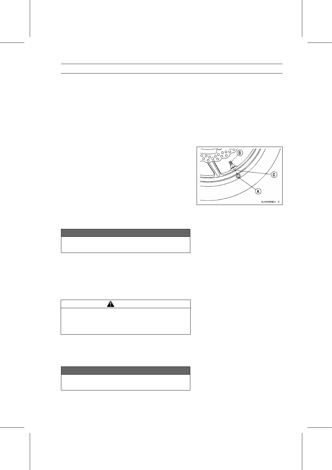
To maintain wheel balance, mark the valve stem position
on the tire with chalk so that the tire can be reinstalled in
the same position.

Chalk Mark or Yellow Mark [A]
Valve Stem [B]
Align [C]

Lubricate the tire beads and rim flanges on both sides with
a soap and water solution or rubber lubricant. This helps
the tire beads slip off the rim flanges.

NOTICE

Never lubricate with engine oil or petroleum distil-
lates because they will deteriorate the tire.

Remove the tire from the rim using a suitable commer-
cially available tire changer.

NOTE

The tires cannot be removed with hand tools because
they fit the rims too tightly.

Tire Installation

WARNING

Mixing tire brands and types can adversely affect
handling and cause an accident resulting in injury
or death. Always use the same manufacturer’s tires
on both front and rear wheels.

Inspect the rim and tire, and replace them if necessary.

Clean the sealing surfaces of the rim and tire, and smooth
the sealing surfaces of the rim with a fine emery cloth if
necessary.

Remove the air valve and discard it.

NOTICE

Replace the air valve whenever the tire is replaced.
Do not reuse the air valve.

10-14 WHEELS/TIRES

Tires

Install a new valve in the rim.

Remove the valve cap, lubricate the stem seal [A] with a
soap and water solution or rubber lubricant, and pull [B]
the valve stem through the rim from the inside out until it
snaps into place.

NOTICE

Do not use engine oil or petroleum distillates to lu-
bricate the stem because they will deteriorate the
rubber.

The air valve is as shown.

Valve Cap [A]
Valve Core [B]
Stem Seal [C]
Valve Stem [D]
Valve Seat [E]
Valve Opened [F]

Check the tire rotation mark on the front and rear tires and
install them on the rim accordingly.

Tire Rotation Mark [A]
Rotating Direction [B]

Position the tire on the rim so that the valve [A] align with
the tire balance mark [B] (the chalk mark made during
removal, or the yellow paint mark on a new tire).

Install the tire bead over the rim flange using a suitable
commercially available tire changer.

Lubricate the tire beads and rim flanges with a soap and
water solution or rubber lubricant to help seat the tire
beads in the sealing surfaces of the rim while inflating the
tire.

Center the rim in the tire beads, and inflate the tire with
compressed air until the tire beads seat in the sealing
surfaces.

WARNING

Overinflating a tire can cause it to explode, causing
serious injury or death. Be sure to install the valve
core whenever inflating the tire, and do not inflate
the tire to more than 400 kPa (4.0 kgf/cm², 57 psi).

WHEELS/TIRES 10-15

Tires

Check to see that the rim lines [A] on both sides of the tire
sidewalls are parallel with the rim flanges.
If the rim flanges and tire sidewall rim lines are not parallel,
remove the valve core.

Lubricate the rim flanges and tire beads.

Install the valve core and inflate the tire again.

After the tire beads seat in the rim flanges, check for air
leakage.

Inflate the tire slightly above standard inflation.

Use a soap and water solution or submerge the tire, and
check for bubbles that would indicate leakage.

Adjust the air pressure to the specified pressure (see Air
Pressure Inspection in the Periodic Maintenance chap-
ter).

Install the air valve cap.

Adjust the wheel balance (see Balance Adjustment).

Tire Repair

Currently two types of repair for tubeless tires have come

into wide use. One type is called a temporary (external) re-
pair which can be carried out without removing the tire from
the rim, and the other type is called permanent (internal)
repair which requires tire removal. It is generally under-
stood that higher running durability is obtained by perma-
nent (internal) repairs than by temporary (external) ones.
Also, permanent (internal) repairs have the advantage of
permitting a thorough examination for secondary damage
not visible from external inspection of the tire. For these
reasons, Kawasaki does not recommend temporary (exter-
nal) repair. Only appropriate permanent (internal) repairs
are recommended. Repair methods may vary slightly from
make to make. Follow the repair methods indicated by the
manufacturer of the repair tools and materials so that safe
results can be obtained.

10-16 WHEELS/TIRES

Hub Bearing

Hub Bearing Removal

Remove the wheels (see Front/Rear Wheel Removal),
and take out the following.

Collars
Coupling (Out of rear hub)
Grease Seals

Use the bearing remover to remove the hub bearings [A].

NOTICE

Do not lay the wheel on the ground with the disc
facing down. This can damage or warp the disc.
Place blocks under the wheel so that the disc does
not touch the ground.

Special Tools - Bearing Remover Head,

25 ×

28 [B]:

57001-1346

Bearing Remover Shaft,

13 [C]: 57001

-1377

Hub Bearing Installation

Before installing the hub bearings, blow any dirt or foreign
particles out of the hub with compressed air to prevent
contamination of the bearings.

Replace the bearings with new ones.

Install the bearings by using the bearing driver set which
does not contact the bearing inner race.

NOTE

Install the bearings so that the marked side faces out.

Press in each right the bearing [A] until they are bottomed.

Special Tool - Bearing Driver Set [B]: 57001-1129

Replace the grease seals with new ones.

Press in the grease seals [A] so that the seal surface is
flush [B] with the end of the hole.

Apply high-temperature grease to the grease seal lips.

Special Tool - Bearing Driver Set [C]: 57001-1129

Hub Bearing Inspection

Since the hub bearings are made to extremely close tol-

erances, the clearance can not normally be measured.

NOTE

Do not remove any bearings for inspection. If any bear-
ings are removed, they will need to be replaced with
new ones.

Turn each bearing in the hub back and forth [A] while
checking for plays, roughness, or binding.
If bearing play, roughness or binding is found, replace the
bearing.

Examine the bearing seal [B] for tears or leakage.
If the seal is torn or is leaking, replace the bearing.

WHEELS/TIRES 10-17

Hub Bearing

Hub Bearing Lubrication

NOTE

Since the hub bearings are packed with grease and
sealed, lubrication is not required.

FINAL DRIVE 11-1

11

Final Drive

Table of Contents

Exploded View .......................................................................................................................

11-2

Specifications ........................................................................................................................

11-4

Special Tools ..........................................................................................................................

11-5

Drive Chain.............................................................................................................................

11-6

Drive Chain Slack Inspection ............................................................................................

11-6

Drive Chain Slack Adjustment ..........................................................................................

11-6

Wheel Alignment Inspection/Adjustment ..........................................................................

11-6

Drive Chain Wear Inspection ............................................................................................

11-6

Drive Chain Lubrication.....................................................................................................

11-6

Drive Chain Guide Wear Inspection..................................................................................

11-6

Drive Chain Removal/Installation......................................................................................

11-6

Sprocket, Coupling .................................................................................................................

11-10

Engine Sprocket Removal ................................................................................................

11-10

Engine Sprocket Installation .............................................................................................

11-10

Engine Sprocket Cover Disassembly................................................................................

11-11

Engine Sprocket Cover Assembly ....................................................................................

11-11

Rear Sprocket Removal....................................................................................................

11-12

Rear Sprocket Installation.................................................................................................

11-12

Coupling Installation..........................................................................................................

11-12

Coupling Bearing Removal ...............................................................................................

11-13

Coupling Bearing Installation ............................................................................................

11-13

Coupling Bearing Inspection .............................................................................................

11-13

Coupling Bearing Lubrication............................................................................................

11-13

Coupling Damper Inspection.............................................................................................

11-14

Sprocket Wear Inspection.................................................................................................

11-14

Rear Sprocket Warp Inspection ........................................................................................

11-14

11-2 FINAL DRIVE

Exploded View

FINAL DRIVE 11-3

Exploded View

Torque

No.

Fastener

N·m

kgf·m

ft·lb

Remarks

1

Engine Sprocket Cover Bolts (L = 55)

9.8

1.0

87 in·lb

2

Engine Sprocket Cover Bolts (L = 45)

9.8

1.0

87 in·lb

3

Engine Sprocket Cover Damper Screws

3.0

0.31

27 in·lb

4

Chain Guide Bolts

12

1.2

106 in·lb

L

5

Engine Sprocket Nut

147

15.0

108

MO

6

Rear Axle Nut

127

13.0

93.7

7

Rear Sprocket Nuts

59

6.0

44

R

G: Apply grease.

HG: Apply high-temperature grease.
HO: Apply heavy oil.

L: Apply a non-permanent locking agent.

MO: Apply molybdenum disulfide oil solution.

(mixture of the engine oil and molybdenum disulfide grease in a weight ratio 10:1)

R: Replacement Parts

11-4 FINAL DRIVE

Specifications

Item

Standard

Service Limit

Drive Chain

Drive Chain Slack

30

40 mm (1.2

1.6 in.)

– – –

Drive Chain Wear (20-link Length) 317.5

318.2 mm (12.50

12.53 in.)

319 mm (12.6 in.)

Standard Chain:

Make

ENUMA

– – –

Type

EX520RMX/3D

– – –

Link

112 links

– – –

Sprockets

Rear Sprocket Warp

TIR 0.4 mm (0.016 in.) or less

TIR 0.5 mm (0.020 in.)

FINAL DRIVE 11-5

Special Tools

Inside Circlip Pliers:
57001-143

Bearing Driver Set:
57001-1129

11-6 FINAL DRIVE

Drive Chain

Drive Chain Slack Inspection

Refer to the Drive Chain Slack Inspection in the Periodic
Maintenance chapter.

Drive Chain Slack Adjustment

Refer to the Drive Chain Slack Adjustment in the Periodic
Maintenance chapter.

Wheel Alignment Inspection/Adjustment

Refer to the Wheel Alignment Inspection in the Periodic
Maintenance chapter.

Drive Chain Wear Inspection

Refer to the Drive Chain Wear Inspection in the Periodic
Maintenance chapter.

Drive Chain Lubrication

Refer to the Drive Chain Lubrication Condition Inspection
in the Periodic Maintenance chapter.

Drive Chain Guide Wear Inspection

Refer to the Chain Guide Wear Inspection in the Periodic
Maintenance chapter.

Drive Chain Removal/Installation

NOTE

Since the drive chain is installed through the swingarm,
The chain can not be removed other than by cutting it.
Prepare the new link pin, link plate, grease seals, and
tools for rejoining the chain.

Remove:

Front Footpeg Bracket Bolts [A]
Front Footpeg Bracket [B]

Remove:

Bolts [A]
Quick Rivet [B]
Chain Cover [C]

Push the central pin, and then remove the quick rivet.

NOTICE

For safety, if the drive chain shall be replaced, re-
place it using a recommended tool.

Recommended Tool - Type: EK Joint Tool #50

Brand: ENUMA

FINAL DRIVE 11-7

Drive Chain

Body [A]
Handlebar [B]
Cutting and Riveting Pin [C]
For Cutting [D]
For Riveting [E]
Plate Holder (A) [F]
Plate Holder (B) [G]
Gauge [H]

Grind [A] the pin head to make it flat.

Set the cutting and riveting pin [B] as shown.

Screw the pin holder until it touches the link pin.

Be sure that the cutting pin hits center of the link pin.

Screw the handlebar [A] into the body.

Turn the pin holder with the wrench [B] clockwise to ex-
tract the link pin.

Replace the link pin, link plate and grease seals.

Apply grease to the link pins [A] and grease seals [B] [C].

Engage the drive chain on the engine and rear sprockets.

Insert the link pins in the drive chain ends.

Install the grease seals.

Install the link plate so that the mark [D] faces out.

Push the link plate by hand or plier to fix it.

Be sure to set the grease seals correctly.

11-8 FINAL DRIVE

Drive Chain

Set the plate holder (A) [A] and plate holder (B) [B] on the
body.

Fit the plate holder (A) to the link plate.

Turn the pin holder by hand until the plate holder (B)
touches the other link plate.

Turn the pin holder by a wrench clockwise until two pins
of link come into groove of the plate holder (A).

Take off the plate holder.

Set the plate holder (B) [A] and cutting and riveting pin [B]
as shown.

Turn the pin holder until the riveting pin touches the link
pin.

FINAL DRIVE 11-9

Drive Chain

Turn the wrench clockwise until the tip of riveting pin hits
of the link pin.

Rivet it.

Same work for the other link pin.

After staking, check the staked area of the link pin for
cracks.

Measure the outside diameter [A] of the link pin and link
plates width [B].

Link Pin Outside Diameter

Standard:

5.6

6.0 mm (0.22

0.24 in.)

Link Plates Outside Width

Standard:

16.40

16.55 mm (0.646

0.652 in.)

If the reading exceeds the specified length, cut and rejoin
the chain again.

Check:

Movement of the Rollers

Adjust the drive chain slack after installing the chain (see
Drive Chain Slack Adjustment in the Periodic Mainte-
nance chapter).

Install the chain cover [A].

Apply a non-permanent locking agent to the threads of
the bolts [B] and tighten them.

Set the quick rivet [C] and push the core of it.

Install the front footpeg bracket.

Apply a non-permanent locking agent to the threads of
the front footpeg bracket bolts, and tighten them.

Torque - Front Footpeg Bracket Bolts: 25 N·m (2.5 kgf·m,

18 ft·lb)

11-10 FINAL DRIVE

Sprocket, Coupling

Engine Sprocket Removal

Remove:

Engine Sprocket Cover Bolts [A]
Engine Sprocket Cover [B]

Flatten out the bended washer [A].

Remove the engine sprocket nut [B] and washer.

NOTE

When loosening the engine sprocket nut, hold the rear
brake on.

Raise the rear wheel off the ground with the stand.

Loosen the drive chain (see Drive Chain Slack Adjust-
ment in the Periodic Maintenance chapter).

Pull the engine sprocket [A] with drive chain [B] off the
output shaft [C].

Disengage the drive chain from the engine sprocket.

Engine Sprocket Installation

Replace the sprocket washer and axle cotter pin.

Install the engine sprocket [A] onto the output shaft.

Apply molybdenum disulfide oil solution to the threads
and seating surface of the engine sprocket nut.

Tighten:

Torque - Engine Sprocket Nut: 147 N·m (15.0 kgf·m, 108

ft·lb)

NOTE

Tighten the engine sprocket nut while applying the rear
brake.

After torquing the engine sprocket nut, bend [B] the one
side of the washer over the nut.

Adjust the drive chain slack after installing the engine
sprocket (see Drive Chain Slack Adjustment in the Pe-
riodic Maintenance chapter).

FINAL DRIVE 11-11

Sprocket, Coupling

Install:

Engine Sprocket Cover [A]

Tighten:

Torque - Engine Sprocket Cover Bolts [B]: 9.8 N·m (1.0

kgf·m, 87 in·lb)

Engine Sprocket Cover Disassembly

Remove:

Engine Sprocket Cover (see Engine Sprocket Removal)
Chain Guide Bolts [A]
Chain Guide [B]

Remove:

Engine Sprocket Cover Damper Screws [A]
Damper [B]

Engine Sprocket Cover Assembly

Fit the grooves of the damper [A] to the ribs [B] of the
engine sprocket cover [C].

Tighten:

Torque - Engine Sprocket Cover Damper Screws [D]: 3.0

N·m (0.31 kgf·m, 27 in·lb)

Install the chain guide [E].

Apply a non-permanent locking agent to the threads of
the chain guide bolts [F], and tighten them.

Torque - Chain Guide Bolts: 12 N·m (1.2 kgf·m, 106 in·lb)

Install:

Engine Sprocket Cover (see Engine Sprocket Installa-
tion)

11-12 FINAL DRIVE

Sprocket, Coupling

Rear Sprocket Removal

Remove the rear wheel (see Rear Wheel Removal in the
Wheels/Tires chapter).

NOTICE

Do not lay the wheel on the ground with the disc
facing down. This can damage or warp the disc.
Place blocks under the wheel so that the disc does
not touch the ground.

Remove:

Rear Sprocket Nuts [A]
Rear Sprocket [B]

Rear Sprocket Installation

Install the sprocket facing the tooth number marking [A]
outward.

Replace the rear sprocket nuts with new ones.

Tighten:

Torque - Rear Sprocket Nuts: 59 N·m (6.0 kgf·m, 44 ft·lb)

Install the rear wheel (see Rear Wheel Installation in the
Wheels/Tires chapter).

Coupling Installation

Apply high-temperature grease to the following.

Coupling Grease Seal Lips [A]
Coupling Internal Surface [B]
Ball Bearing [C]

Install:

Collar [A]
Coupling

FINAL DRIVE 11-13

Sprocket, Coupling

Coupling Bearing Removal

Remove:

Coupling
Grease Seal
Circlip [A]

Special Tool - Inside Circlip Pliers: 57001-143

Remove the bearing [A] by tapping from the wheel side.

Special Tool - Bearing Driver Set [B]: 57001-1129

Coupling Bearing Installation

Replace the bearing with a new one.

Press in the bearing [A] until it is bottomed.

Special Tool - Bearing Driver Set [B]: 57001-1129

Pack the bearing with high-temperature grease.

Replace the circlip with a new one.

Special Tool - Inside Circlip Pliers: 57001-143

Replace the grease seal with a new one.

Press in the grease seal so that the seal surface is flush
with the end of the hole.

Apply high-temperature grease to the grease seal lips.

Special Tool - Bearing Driver Set: 57001-1129

Coupling Bearing Inspection

Since the coupling bearing is made to extremely close

tolerances, the clearance can not normally be measured.

NOTE

It is not necessary to remove the coupling bearing for
inspection. If the bearing is removed, it will need to be
replaced with a new one.

Turn the bearing in the coupling back and forth [A] while
checking for plays, roughness or binding.
If the bearing play, roughness or binding is found, replace
the bearing.

Coupling Bearing Lubrication

Pack the bearing with high-temperature grease. Turn the
bearing around by hand a few times to make sure the
grease is distributed uniformly inside the bearing.

11-14 FINAL DRIVE

Sprocket, Coupling

Coupling Damper Inspection

Remove the rear wheel coupling, and inspect the rubber
dampers [A].

Replace the damper if it appears damaged or deterio-
rated.

Sprocket Wear Inspection

Visually inspect the engine and rear sprocket teeth for
wear and damage.
If the teeth are worn as illustrated, replace the sprocket,
and inspect the drive chain wear (see Drive Chain Wear
Inspection in the Periodic Maintenance chapter).

Worn Tooth (Engine Sprocket) [A]
Worn Tooth (Rear Sprocket) [B]
Direction of Rotation [C]

NOTE

If a sprocket requires replacement, the chain is proba-
bly worn also. When replacing a sprocket, inspect the
chain.

Rear Sprocket Warp Inspection

Raise the rear wheel off the ground with the stand so that
it will turn freely.

Set a dial gauge [A] against the rear sprocket [B] near the
teeth as shown, and rotate [C] the rear wheel to measure
the sprocket runout (warp). The difference between the
highest and lowest dial gauge readings is the amount of
runout (warp).
If the runout exceeds the service limit, replace the rear
sprocket.

Rear Sprocket Warp

Standard:

TIR 0.4 mm (0.016 in.) or less

Service Limit: TIR 0.5 mm (0.020 in.)

BRAKES 12-1

12

Brakes

Table of Contents

Exploded View .......................................................................................................................

12-3

Specifications ........................................................................................................................

12-10

Special Tools ..........................................................................................................................

12-11

Brake Lever, Brake Pedal.......................................................................................................

12-12

Brake Lever Position Adjustment......................................................................................

12-12

Brake Pedal Position Inspection ......................................................................................

12-12

Brake Pedal Position Adjustment .....................................................................................

12-12

Brake Pedal Removal .......................................................................................................

12-12

Brake Pedal Installation ....................................................................................................

12-13

Calipers ..................................................................................................................................

12-15

Front Caliper Removal ......................................................................................................

12-15

Rear Caliper Removal.......................................................................................................

12-15

Caliper Installation ............................................................................................................

12-16

Front Caliper Disassembly................................................................................................

12-16

Front Caliper Assembly.....................................................................................................

12-16

Rear Caliper Disassembly ................................................................................................

12-16

Rear Caliper Assembly .....................................................................................................

12-16

Caliper Fluid Seal Damage Inspection..............................................................................

12-17

Caliper Dust Seal Damage Inspection ..............................................................................

12-17

Rear Caliper Dust Boot and Friction Boot Damage Inspection.........................................

12-17

Caliper Piston and Cylinder Damage Inspection ..............................................................

12-18

Rear Caliper Holder Shaft Wear Inspection......................................................................

12-18

Brake Pads .............................................................................................................................

12-19

Front Brake Pad Removal.................................................................................................

12-19

Front Brake Pad Installation..............................................................................................

12-19

Rear Brake Pad Removal ................................................................................................

12-20

Rear Brake Pad Installation ..............................................................................................

12-20

Brake Pad Wear Inspection ..............................................................................................

12-20

Master Cylinder ......................................................................................................................

12-21

Front Master Cylinder Removal ........................................................................................

12-21

Front Master Cylinder Installation .....................................................................................

12-21

Rear Master Cylinder Removal.........................................................................................

12-22

Rear Master Cylinder Installation......................................................................................

12-23

Front Master Cylinder Disassembly ..................................................................................

12-24

Rear Master Cylinder Disassembly...................................................................................

12-24

Master Cylinder Assembly ................................................................................................

12-24

Master Cylinder Inspection (Visual Inspection).................................................................

12-24

Brake Disc ..............................................................................................................................

12-25

Brake Disc Removal .........................................................................................................

12-25

Brake Disc Installation ......................................................................................................

12-25

Brake Disc Wear Inspection..............................................................................................

12-25

Brake Disc Warp Inspection..............................................................................................

12-26

Brake Fluid .............................................................................................................................

12-27

Brake Fluid Level Inspection.............................................................................................

12-27

Brake Fluid Change ..........................................................................................................

12-27

Brake Line Bleeding..........................................................................................................

12-27

Brake Hose.............................................................................................................................

12-31

Brake Hose Removal/Installation......................................................................................

12-31

Brake Hose Inspection......................................................................................................

12-31

KIBS (Equipped Models) ........................................................................................................

12-32

12-2 BRAKES

Parts Location ...................................................................................................................

12-32

KIBS Servicing Precautions ..............................................................................................

12-36

KIBS Troubleshooting Outline...........................................................................................

12-38

Inquiries to Rider...............................................................................................................

12-41

Self-diagnosis Outline .......................................................................................................

12-43

ABS and KIBS Indicator Lights (LED) Inspection .............................................................

12-44

KIBS Hydraulic Unit Removal ...........................................................................................

12-44

KIBS Hydraulic Unit Installation ........................................................................................

12-45

KIBS Hydraulic Unit Inspection .........................................................................................

12-46

Front Wheel Rotation Sensor Removal ............................................................................

12-46

Front Wheel Rotation Sensor Installation .........................................................................

12-47

Rear Wheel Rotation Sensor Removal .............................................................................

12-47

Rear Wheel Rotation Sensor Installation ..........................................................................

12-48

Wheel Rotation Sensor Inspection....................................................................................

12-48

Wheel Rotation Sensor Air Gap Inspection ......................................................................

12-49

Wheel Rotation Sensor Rotor Inspection..........................................................................

12-49

KIBS Solenoid Valve Relay Fuse (15 A) Removal............................................................

12-50

KIBS Motor Relay Fuse (25 A) Removal ..........................................................................

12-50

Fuse Installation................................................................................................................

12-50

Fuse Inspection.................................................................................................................

12-50

BRAKES 12-3

Exploded View

This page intentionally left blank.

12-4 BRAKES

Exploded View

BRAKES 12-5

Exploded View

Torque

No.

Fastener

N·m

kgf·m

ft·lb

Remarks

1

Front Brake Reservoir Cap Stopper Screw

1.2

0.12

11 in·lb

2

Brake Lever Pivot Bolt

1.0

0.10

8.9 in·lb

Si

3

Front Master Cylinder Bleed Valve

5.4

0.55

48 in·lb

4

Front Master Cylinder Clamp Bolts

11

1.1

97 in·lb

S

5

Brake Lever Pivot Bolt Locknut

5.9

0.60

52 in·lb

6

Front Brake Light Switch Screw

1.2

0.12

11 in·lb

7

Brake Hose Banjo Bolts

25

2.5

18

8

Bleed Valves

7.8

0.80

69 in·lb

9

Front Brake Pad Pins

17

1.7

13

10

Front Caliper Mounting Bolts

34

3.5

25

11

Front Brake Disc Mounting Bolts

27

2.8

20

L

12. Front Wheel Rotation Sensor

B: Apply brake fluid.

L: Apply a non-permanent locking agent.

R: Replacement Parts

S: Follow the specified tightening sequence.

Si: Apply silicone grease.

12-6 BRAKES

Exploded View

BRAKES 12-7

Exploded View

Torque

No.

Fastener

N·m

kgf·m

ft·lb

Remarks

1

Brake Hose Banjo Bolts

25

2.5

18

2

Rear Master Cylinder Mounting Bolts

25

2.5

18

3

Brake Pedal Mounting Bolt

34

3.5

25

L

4

Rear Caliper Pin Bolt

27

2.8

20

Si

5

Bleed Valve

7.8

0.80

69 in·lb

6

Rear Brake Pad Pin Plug

2.45

0.25

22 in·lb

7

Rear Brake Pad Pin

17

1.7

13

8

Rear Brake Disc Mounting Bolts

27

2.8

20

L

9

Rear Master Cylinder Push Rod Locknut

17

1.7

13

10. Rear Wheel Rotation Sensor

B: Apply brake fluid.

L: Apply a non-permanent locking agent.

R: Replacement Parts

Si: Apply silicone grease.

12-8 BRAKES

Exploded View

KIBS Equipped Models

BRAKES 12-9

Exploded View

Torque

No.

Fastener

N·m

kgf·m

ft·lb

Remarks

1

Brake Hose Banjo Bolts

25

2.5

18

2

Brake Pipe Joint Nuts

18

1.8

13

3

Brake Pipe Banjo Bolts (L = 20.8)

23

2.3

17

4

Brake Pipe Banjo Bolt (L = 32.3)

23

2.3

17

5. KIBS Hydraulic Unit

R: Replacement Parts

NOTE

When disassembling the brake hose and pipe, disassemble them by the unit as shown in the
exploded view.

12-10 BRAKES

Specifications

Item

Standard

Service Limit

Brake Lever, Brake Pedal

Brake Lever Position

6-way adjustable (to suit rider)

– – –

Brake Lever Free Play

Non-adjustable

– – –

Pedal Free Play

Non-adjustable

– – –

Pedal Position

About 75 mm (2.95 in.) below top of
footpeg

– – –

Brake Pads

Lining Thickness:

Front

4.0 mm (0.16 in.)

1 mm (0.04 in.)

Rear

5.0 mm (0.20 in.)

1 mm (0.04 in.)

Brake Discs

Thickness:

Front

4.8

5.2 mm (0.19

0.20 in.)

4.5 mm (0.18 in.)

Rear

4.8

5.2 mm (0.19

0.20 in.)

4.5 mm (0.18 in.)

Runout:

Front

TIR 0.15 mm (0.006 in.) or less

TIR 0.3 mm (0.01 in.)

Rear

TIR 0.20 mm (0.008 in.) or less

TIR 0.3 mm (0.01 in.)

KIBS (Equipped Models)

Wheel Rotation Sensor Air
Gap:

Front

0.4

1.6 mm (0.02

0.06 in.)

– – –

Rear

0.4

1.6 mm (0.02

0.06 in.)

– – –

BRAKES 12-11

Special Tools

Jack:
57001-1238

Hand Tester:
57001-1394

Jack Attachment:
57001-1608

12-12 BRAKES

Brake Lever, Brake Pedal

Brake Lever Position Adjustment

The brake lever adjuster has 6 positions so that the brake

lever position can be adjusted to suit the operator’s hand.

Push the lever forward and turn the adjuster [A] to align
the number with the arrow mark [B] on the lever.

The distance from the grip to the lever is minimum at num-
ber 6 and maximum at number 1.

Brake Pedal Position Inspection

Check that the brake pedal [A] is in the correct position.

Footpeg [B]

Pedal Position

Standard:

About 75 mm (2.95 in.) [C] below top of
footpeg

If it is incorrect, adjust the brake pedal position.

Brake Pedal Position Adjustment

NOTE

Usually it is not necessary to adjust the pedal position,
but always adjust it when push rod locknut has been
loosened.

Loosen the locknut [A] and turn the push rod with the hex
head [B] to achieve the correct pedal position.
If the length [C] shown is

70 ±1 mm (2.8 ±0.04 in.)

, the

pedal position will be within the standard range.

Tighten:

Torque - Rear Master Cylinder Push Rod Locknut: 17 N·m

(1.7 kgf·m, 13 ft·lb)

Check the brake light switch operation (see Brake Light
Switch Operation Inspection in the Periodic Maintenance
chapter).

Brake Pedal Removal

Remove:

Rear Master Cylinder Mounting Bolts [A]
Foot Guard [B]
Front Footpeg Bracket Bolts [C]


Content      ..     10      11      12      13     ..