Kawasaki Motorcycle Ninja ZX-6R / Ninja ZX-6R ABS. Service Manual (2013 year) - page 10
 

  Index      Manuals     Kawasaki Motorcycle Ninja ZX-6R / Ninja ZX-6R ABS. Service Manual (2013 year)


Search            copyright infringement  


Content      ..     8      9      10      11     ..


Kawasaki Motorcycle Ninja ZX-6R / Ninja ZX-6R ABS. Service Manual (2013 year) - page 10


ENGINE REMOVAL/INSTALLATION 8-7

Engine Removal/Installation

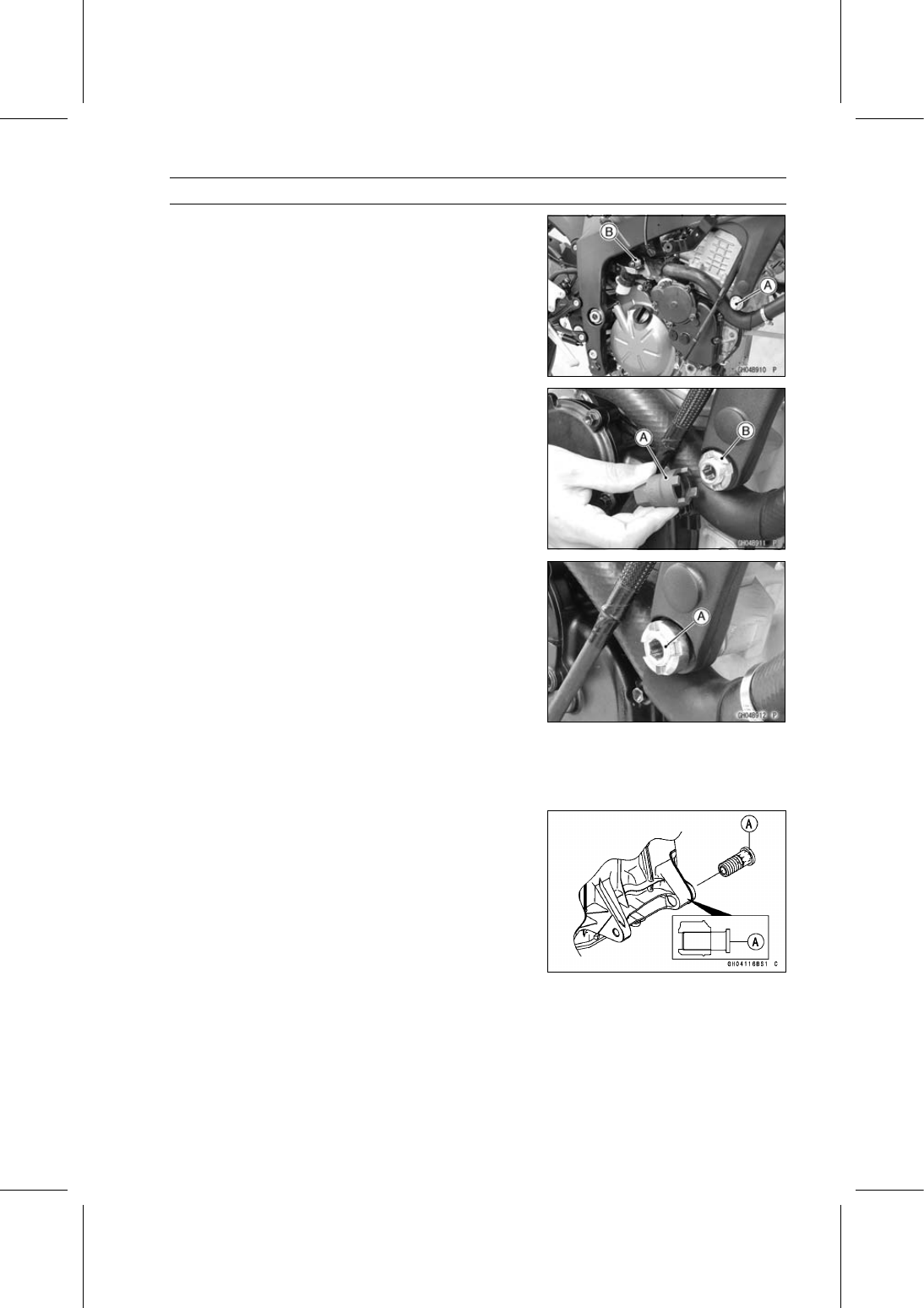
Remove:

Right Front Engine Mounting Bolt [A]
Middle Engine Mounting Nut [B]
Lower Engine Mounting Nut

NOTE

Hold the mounting bolt not to turn when loosening the
middle and lower engine mounting nuts.

Using the engine mount nut wrench [A], loosen the lock-
nuts [B].

Special Tool - Engine Mount Nut Wrench: 57001-1450

Using the Hexagon Wrench, turn the adjusting collars [A]
counterclockwise to make the gap between the engine
and adjusting collar.

Turn the lower engine mounting bolt clockwise to make
the gap between the adjusting collar and frame.

Pull out the engine mounting bolts.

Using the stand, take out the engine.

Engine Installation

Apply molybdenum disulfide grease to the threads of the
adjusting collar [A].

Install the adjusting collar to crankcase backside until end
of the threads.

8-8 ENGINE REMOVAL/INSTALLATION

Engine Removal/Installation

Install the adjusting collars [A] to the frame until end of the
threads.

Replace the engine mounting nuts with new ones.

Support the engine with a suitable stand.

Put a plank onto the suitable stand for engine balance.

Support the engine until all bolts have been tightened.

Install the engine mounting bolts and nuts, following the
specified installing sequence.

First, tighten the following bolts and nuts temporarily.

Lower Engine Mounting Bolt [A] and Nut
Middle Engine Mounting Bolt [B] and Nut
Left Front Engine Mounting Bolt [C]
Right Front Engine Mounting Bolt [D]

ENGINE REMOVAL/INSTALLATION 8-9

Engine Removal/Installation

Second, tighten the left front engine mounting bolt [A].

Frame [B]
Engine [C]

Torque - Left Front Engine Mounting Bolt: 44 N·m (4.5

kgf·m, 32 ft·lb)

Third, tighten the lower engine mounting bolt [A] coun-
terclockwise until the adjusting collar [B] touches [C] the
frame [D].

Fourth, tighten the adjusting collar [E] counterclockwise
until the adjusting collar touches [C] the engine [D].

Fifth, tighten the adjusting collars [B] and [E] .

Torque - Adjusting Collars: 9.8 N·m (1.0 kgf·m, 87 in·lb)

Sixth, tighten the adjusting collar locknut [F].

Special Tool - Engine Mount Nut Wrench: 57001-1450

Torque - Adjusting Collar Locknut: 49 N·m (5.0 kgf·m, 36

ft·lb)

Seventh, tighten the lower and middle engine mounting
nuts.

Torque - Lower Engine Mounting Nut [G]: 44 N·m (4.5

kgf·m, 32 ft·lb)

Middle Engine Mounting Nut [H]: 44 N·m (4.5

kgf·m, 32 ft·lb)

NOTE

Hold the mounting bolt not to turn when tightening the
middle and lower engine mounting nuts.

Eighth, remove the right front engine mounting bolt [A],
and tighten the adjusting collar [B] counterclockwise until
the clearance [C] between the engine [D] and collar come
to 0 mm (0 in.).

Ninth, tighten the adjusting collar locknut [E].

Special Tool - Engine Mount Nut Wrench: 57001-1450

Torque - Adjusting Collar Locknut: 49 N·m (5.0 kgf·m, 36

ft·lb)

Lastly, tighten the right front engine mounting bolt.

Torque - Right Front Engine Mounting Bolt: 44 N·m (4.5

kgf·m, 32 ft·lb)

8-10 ENGINE REMOVAL/INSTALLATION

Engine Removal/Installation

Run the leads, cables and hoses correctly (see Cable,
Wire, and Hose Routing section in the Appendix chapter).

Install the removed parts (see appropriate chapters).

Adjust:

Throttle Cables (see Throttle Control System Inspection
in the Periodic Maintenance chapter)
Clutch Cable (see Clutch Operation Inspection in the Pe-
riodic Maintenance chapter)
Drive Chain (see Drive Chain Slack Inspection in the
Periodic Maintenance chapter)

Fill the engine with engine oil (see Engine Oil Change in
the Periodic Maintenance chapter).

Fill the engine with coolant (see Coolant Change in the
Periodic Maintenance chapter).

CRANKSHAFT/TRANSMISSION 9-1

9

Crankshaft/Transmission

Table of Contents

Exploded View...................................

9-2

Specifications ....................................

9-6

Special Tools and Sealants ...............

9-9

Crankcase .........................................

9-11

Crankcase Splitting ......................

9-11

Crankcase Assembly ...................

9-12

Crankshaft and Connecting Rods......

9-17

Crankshaft Removal ....................

9-17

Crankshaft Installation .................

9-17

Connecting Rod Removal ............

9-18

Connecting Rod Installation .........

9-19

Crankshaft/Connecting Rod

Cleaning ....................................

9-22

Connecting Rod Bend Inspection

9-22

Connecting Rod Twist Inspection.

9-22

Connecting Rod Big End Side

Clearance Inspection ................

9-23

Connecting Rod Big End

Bearing Insert/Crankpin Wear
Inspection..................................

9-23

Crankshaft Side Clearance

Inspection..................................

9-25

Crankshaft Runout Inspection......

9-25

Crankshaft Main Bearing

Insert/Journal Wear Inspection .

9-25

Pistons...............................................

9-28

Piston Removal............................

9-28

Piston Installation.........................

9-29

Cylinder (Upper Crankcase) Wear

Inspection..................................

9-30

Piston Wear Inspection ................

9-30

Piston Ring, Piston Ring Groove

Wear Inspection ........................

9-30

Piston Ring Groove Width

Inspection..................................

9-31

Piston Ring Thickness Inspection

9-31

Piston Ring End Gap Inspection ..

9-31

Starter Idle Gear and Starter Clutch ..

9-32

Starter Idle Gear Removal ...........

9-32

Starter Idle Gear Installation ........

9-32

Starter Clutch Removal................

9-34

Starter Clutch Installation ............

9-34

Starter Clutch Disassembly..........

9-34

Starter Clutch Assembly ..............

9-35

Starter Clutch Inspection..............

9-35

Transmission .....................................

9-37

Transmission Assy Removal........

9-37

Transmission Assy Disassembly .

9-37

Transmission Assy Assembly ......

9-37

Transmission Assy Installation.....

9-39

Transmission Shaft Removal .......

9-40

Transmission Shaft Installation ....

9-40

Transmission Shaft Disassembly .

9-40

Transmission Shaft Assembly......

9-40

Shift Drum and Fork Removal......

9-44

Shift Drum and Fork Installation...

9-44

Shift Drum Disassembly...............

9-44

Shift Drum Assembly ...................

9-44

Shift Fork Bending Inspection ......

9-44

Shift Fork/Gear Groove Wear

Inspection..................................

9-44

Shift Fork Guide Pin/Drum

Groove Wear Inspection ...........

9-45

Gear Dog and Gear Dog Hole

Damage Inspection ...................

9-45

External Shift Mechanism..................

9-46

Shift Pedal Removal ....................

9-46

Shift Pedal Installation .................

9-46

External Shift Mechanism

Removal ....................................

9-46

External Shift Mechanism

Installation .................................

9-47

External Shift Mechanism

Inspection..................................

9-48

9-2 CRANKSHAFT/TRANSMISSION

Exploded View

CRANKSHAFT/TRANSMISSION 9-3

Exploded View

Torque

No.

Fastener

N·m

kgf·m

ft·lb

Remarks

1

Breather Hose Fitting

15

1.5

11

L

2

Transmission Case Bolts (M8)

20

2.0

15

3

Transmission Case Bolt (M6)

9.8

1.0

87 in·lb

4

Bearing Holder Screws

4.9

0.50

43 in·lb

L

5

Oil Jet Nozzles

2.9

0.30

26 in·lb

6

Race Holder Screws

4.9

0.50

43 in·lb

L

7

Breather Plate Bolts

9.8

1.0

87 in·lb

L

8

Oil Passage Plugs (Taper)

20

2.0

15

L

9

Oil Passage Nozzle

4.9

0.50

43 in·lb

10

Oil Passage Plug

17

1.7

13

11

Connecting Rod Big End Nuts

see the text

MO

12

Crankcase Bolts (M6, L = 68 mm)

12

1.2

106 in·lb

S

13

Crankcase Bolt (M8, L = 90 mm)

27

2.8

20

S

14

Crankcase Bolts (M8, L = 75 mm)

27

2.8

20

S

15

Crankcase Bolts (M6, L = 50 mm)

12

1.2

106 in·lb

16

Crankcase Bolts (M8, L = 95 mm)

31

3.2

23

MO, S

EO: Apply engine oil.

G: Apply grease.

L: Apply a non-permanent locking agent.

LG: Apply liquid gasket.

M: Apply molybdenum disulfide grease.

MO: Apply molybdenum disulfide oil solution.

(mixture of the engine oil and molybdenum disulfide grease in a weight ratio 10:1)

R: Replacement Parts

S: Follow the specified tightening sequence.

9-4 CRANKSHAFT/TRANSMISSION

Exploded View

CRANKSHAFT/TRANSMISSION 9-5

Exploded View

Torque

No.

Fastener

N·m

kgf·m

ft·lb

Remarks

1

Gear Positioning Lever Bolt

12

1.2

106 in·lb

2

Shift Drum Cam Holder Bolt

12

1.2

106 in·lb

L

3

Gear Position Switch Screws

2.9

0.30

26 in·lb

L

4

Shift Shaft Return Spring Pin

28

2.9

21

L

5

Starter Clutch Cover Bolts (L = 30 mm)

9.8

1.0

87 in·lb

6

Starter Clutch Cover Bolt (L = 20 mm)

9.8

1.0

87 in·lb

7

Idle Gear Cover Bolts

9.8

1.0

87 in·lb

8

Shift Pedal Mounting Bolt

25

2.5

18

L

9

Starter Clutch Bolt

49

5.0

36

EO: Apply engine oil.

G: Apply grease.

L: Apply a non-permanent locking agent.

Lh: Left-hand Threads

M: Apply molybdenum disulfide grease.

MO: Apply molybdenum disulfide oil solution.

(mixture of the engine oil and molybdenum disulfide grease in a weight ratio 10:1)

R: Replacement Parts

9-6 CRANKSHAFT/TRANSMISSION

Specifications

Item

Standard

Service Limit

Crankcase, Crankshaft, Connecting
Rods

Connecting Rod Bend

– – –

TIR 0.2/100 mm

(0.008/3.94 in.)

Connecting Rod Twist

– – –

TIR 0.2/100 mm

(0.008/3.94 in.)

Connecting Rod Big End Side
Clearance

0.13

0.38 mm (0.0051

0.0150 in.)

0.58 mm

(0.023 in.)

Connecting Rod Big End Bearing
Insert/Crankpin Clearance

0.044

0.081 mm (0.0017

0.0032 in.)

0.11 mm

(0.0043 in.)

Crankpin Diameter:

29.984

30.000 mm (1.1805

1.1811 in.)

29.97 mm

(1.1799 in.)

Marking:

None

29.984

29.992 mm (1.1805

1.1808 in.)

– – –

29.993

30.000 mm (1.1808

1.1811 in.)

– – –

Connecting Rod Big End Inside
Diameter:

33.000

33.016 mm (1.2992

1.2998 in.)

– – –

Marking:

None

33.000

33.008 mm (1.2992

1.2995 in.)

– – –

33.009

33.016 mm (1.2996

1.2998 in.)

– – –

Connecting Rod Big End Bearing
Insert Thickness:

Brown

1.475

1.480 mm (0.05807

0.05827 in.)

– – –

Black

1.480

1.485 mm (0.05827

0.05846 in.)

– – –

Blue

1.485

1.490 mm (0.05846

0.05866 in.)

– – –

Connecting Rod Bolt Stretch

(Usable Range)

0.28

0.38 mm (0.0110

0.0150 in.)

– – –

Crankshaft Side Clearance

0.05

0.25 mm (0.0020

0.0098 in.)

0.45 mm

(0.0177 in.)

Crankshaft #3 Main Journal Width

21.09

21.14 mm (0.8303

0.8323 in.)

– – –

Crankshaft Runout

TIR 0.02 mm (0.0008 in.) or less

TIR 0.05 mm

(0.0020 in.)

Crankshaft Main Bearing
Insert/Journal Clearance

0.028

0.060 mm (0.0011

0.0024 in.)

0.09 mm

(0.0035 in.)

Crankshaft Main Journal Diameter:

30.984

31.000 mm (1.2198

1.2205 in.)

30.96 mm

(1.2189 in.)

Marking:

None

30.984

30.992 mm (1.2198

1.2202 in.)

– – –

1

30.993

31.000 mm (1.2202

1.2205 in.)

– – –

Crankcase Main Bearing Inside
Diameter:

34.000

34.016 mm (1.3386

1.3392 in.)

– – –

Marking

34.000

34.008 mm (1.3386

1.3389 in.)

– – –

None

34.009

34.016 mm (1.3389

1.3392 in.)

– – –

CRANKSHAFT/TRANSMISSION 9-7

Specifications

Item

Standard

Service Limit

Crankshaft Main Bearing Insert
Thickness:

Brown, Yellow

1.491

1.495 mm (0.05870

0.05886 in.)

– – –

Black, Green

1.495

1.499 mm (0.05886

0.05902 in.)

– – –

Blue, Purple

1.499

1.503 mm (0.05902

0.05917 in.)

– – –

Cylinder , Pistons

Cylinder (Upper Crankcase) Inside
Diameter

67.000

67.012 mm (2.6378

2.6383 in.)

67.09 mm

(2.6413 in.)

Piston Diameter

66.960

66.975 mm (2.6362

2.6368 in.)

66.81 mm

(2.6303 in.)

Piston/Cylinder Clearance

0.025

0.052 mm (0.0010

0.0020 in.)

– – –

Piston Ring/Groove Clearance:

Top

0.03

0.07 mm (0.0012

0.0028 in.)

0.17 mm

(0.0067 in.)

Second

0.03

0.07 mm (0.0012

0.0028 in.)

0.17 mm

(0.0067 in.)

Piston Ring Groove Width:

Top

0.82

0.84 mm (0.0323

0.0331 in.)

0.92 mm

(0.036 in.)

Second

0.82

0.84 mm (0.0323

0.0331 in.)

0.92 mm

(0.036 in.)

Piston Ring Thickness:

Top

0.77

0.79 mm (0.0303

0.0311 in.)

0.70 mm

(0.028 in.)

Second

0.77

0.79 mm (0.0303

0.0311 in.)

0.70 mm

(0.028 in.)

Piston Ring End Gap:

Top

0.12

0.22 mm (0.0047

0.0087 in.)

0.5 mm

(0.020 in.)

Second

0.30

0.45 mm (0.0118

0.0177 in.)

0.8 mm

(0.031 in.)

Transmission

Shift Fork Ear Thickness

5.9

6.0 mm (0.232

0.236 in.)

5.8 mm

(0.228 in.)

Gear Groove Width

6.05

6.15 mm (0.238

0.242 in.)

6.25 mm

(0.246 in.)

Shift Fork Guide Pin Diameter

5.9

6.0 mm (0.232

0.236 in.)

5.8 mm

(0.228 in.)

Shift Drum Groove Width

6.05

6.20 mm (0.238

0.244 in.)

6.3 mm

(0.248 in.)

9-8 CRANKSHAFT/TRANSMISSION

Specifications

Connecting Rod Big End Bearing Insert Selection

Bearing Insert

Con-rod Big End

Inside Diameter

Marking

Crankpin Diameter

Marking

Size Color

Part Number

None

Brown

92139-0167

None

None

Black

92139-0166

None

Blue

92139-0165

Crankshaft Main Bearing Insert Selection

Bearing Insert*

Crankcase Main

Bearing Inside

Diameter Marking

Crankshaft Main

Journal Diameter

Marking

Size Color

Part Number

Journal Nos.

92139-0247

1, 5

Brown

92139-0250

2, 4

1

Yellow

92139-0253

3

92139-0246

1, 5

Black

92139-0249

2, 4

None

1

Green

92139-0252

3

92139-0246

1, 5

Black

92139-0249

2, 4

None

Green

92139-0252

3

92139-0245

1, 5

Blue

92139-0248

2, 4

None

None

Purple

92139-0251

3

*: The bearing inserts for Nos. 2 and 4 journals have an oil groove, respectively.

CRANKSHAFT/TRANSMISSION 9-9

Special Tools and Sealants

Outside Circlip Pliers:
57001-144

Piston Pin Puller Assembly:
57001-910

Piston Ring Compressor Grip:
57001-1095

Piston Ring Compressor Belt,

67

79:

57001-1097

Bearing Driver Set:
57001-1129

Grip:
57001-1591

Rotor Holder:
57001-1666

Stopper:
57001-1679

Rotor Holder Attachment:
57001-1689

Liquid Gasket, TB1211F:
92104-0004

9-10 CRANKSHAFT/TRANSMISSION

Special Tools and Sealants

Liquid Gasket, TB1216B:
92104-1064

CRANKSHAFT/TRANSMISSION 9-11

Crankcase

Crankcase Splitting

Remove the engine (see Engine Removal in the Engine
Removal/Installation chapter).

Set the engine on a clean surface and hold the engine
steady while parts are being removed.

Remove:

Crankshaft Sensor (see Crankshaft Sensor Removal in
the Electrical System chapter)
Starter Clutch (see Starter Clutch Removal)
Cylinder Head (see Cylinder Head Removal in the En-
gine Top End chapter)
Starter Motor (see Starter Motor Removal in the Electri-
cal System chapter)
Clutch (see Clutch Removal in the Clutch chapter)
Oil Pump (see Oil Pump Removal in the Engine Lubri-
cation System chapter)
Alternator Rotor (see Alternator Rotor Removal in the
Electrical System chapter)
Oil Cooler/Oil Filter Case (see Oil Cooler/Oil Filter Case
Removal in the Engine Lubrication System chapter)
Oil Pan (see Oil Pan Removal in the Engine Lubrication
System chapter)
Oil Screen (see Oil Pressure Relief Valve Removal in the
Engine Lubrication System chapter)
External Shift Mechanism (see External Shift Mecha-
nism Removal)
Transmission Assy (see Transmission Assy Removal)

Remove the upper crankcase bolts, following the speci-
fied sequence.

Firstly, loosen the M6 bolts [A].

Secondly, loosen the M8 bolts [B].

Remove the lower crankcase bolts, following the specified
sequence.

Firstly, loosen the M6 bolts [A].

Lastly, loosen the M8 bolts [B] as shown sequence [1

10].

Tap lightly around the crankcase mating surface with a
plastic mallet, and split the crankcase.

Take care not to damage the crankcase.

9-12 CRANKSHAFT/TRANSMISSION

Crankcase

Crankcase Assembly

NOTICE

The upper and lower crankcase halves are ma-
chined at the factory in the assembled state, so the
crankcase halves must be replaced as a set.

With a high flash-point solvent, clean off the mating sur-
faces of the crankcase halves and wipe dry.

WARNING

Gasoline and low flash-point solvents can be
flammable and/or explosive and cause severe
burns.

Clean the crankcase in a well-ventilated

area, and take care that there are no sparks or
flame anywhere near the working area; this in-
cludes any appliance with a pilot light. Do not use
gasoline or a low flash-point solvent to clean the
crankcase.

Using compressed air, blow out the oil passages in the
crankcase halves.

Upper Crankcase Assembly

When installing the breather plate note the following.

Replace the gasket [A] with a new one.

Apply a non-permanent locking agent to the threads of
the bolts [A] and tighten them.

Torque - Breather Plate Bolts: 9.8 N·m (1.0 kgf·m, 87 in·lb)

CRANKSHAFT/TRANSMISSION 9-13

Crankcase

Press the fitting [A] until it is bottomed.

Special Tool - Bearing Driver Set: 57001-1129

Apply a non-permanent locking agent to the threads of
the breather hose fitting [B] and tighten it.

View from Upside [C]

Torque - Breather Hose Fitting: 15 N·m (1.5 kgf·m, 11 ft·lb)

Install the plug [D] so that the plug surface [E] is flush with
the end of the hole.

View from Left Side [F]

Install the oil jet nozzles [A], and tighten them.

Torque - Oil Jet Nozzles: 2.9 N·m (0.30 kgf·m, 26 in·lb)

Install:

Position Ring [B]
Ball Bearing [C]

Lower Crankcase Assembly

Press the race [A] so that the big stepped side faces to
inside of the crankcase until it is bottomed.

Install the race holder [B] as shown.

Apply a non-permanent locking agent to the threads of
the race holder screw [C].

Tighten:

Torque - Race Holder Screws: 4.9 N·m (0.50 kgf·m, 43 in·lb)

Apply a non-permanent locking agent to the oil passage
plugs [D].

Tighten:

Torque - Oil Passage Plugs (Taper): 20 N·m (2.0 kgf·m, 15

ft·lb)

View from Right Side [E]
View from Front Side [F]

9-14 CRANKSHAFT/TRANSMISSION

Crankcase

Press the new needle bearing [A] for the shift shaft so
that its marked side faces outside [B] and its surface [C]
is flush with the end of the hole.

Install the new oil seal [D] so that its surface [E] is flush
with the end of the hole.

Apply grease to the oil seal lips.

Replace the O-ring [F] with a new one.

Apply grease to the O-ring.

Tighten:

Torque - Oil Passage Plug [G]: 17 N·m (1.7 kgf·m, 13 ft·lb)

View from Left Side [H]

Install the oil passage nozzle [A], and tighten it.

Torque - Oil Passage Nozzle: 4.9 N·m (0.50 kgf·m, 43 in·lb)

Crankcase Halves Assembly

Install:

Crankshaft (see Crankshaft Installation)
Connecting Rods (see Connecting Rod Installation)
Dowel Pins [A]
O-rings [B]

Before fitting the lower case on the upper case, check the
following.

Be sure to hang the camshaft chain [C] on the crankshaft.

CRANKSHAFT/TRANSMISSION 9-15

Crankcase

Using a high flash-point solvent, clean off any oil or dirt
that may be on the liquid gasket, coating area. Dry them
with a clean cloth.

Apply liquid gasket [A] to the mating surface of the lower
crankcase half.

Sealant - Liquid Gasket, TB1216B: 92104-1064

NOTE

Especially, apply a sealant so that it shall be filled up on
the groove [B].

Do not apply liquid gasket to the inside of the grooves
[C].

NOTICE

Do not apply liquid gasket around the crankshaft
main bearing inserts and oil passage.

Fit the lower crankcase half to the upper crankcase half.

NOTE

Make the application finish within 20 minutes when
the liquid gasket to the mating surface of the lower
crankcase half is applied.

Moreover fit the case and tighten the bolts just after
application of the liquid gasket.

9-16 CRANKSHAFT/TRANSMISSION

Crankcase

The M8 bolts [A] has a copper plated washer [B], replace
it with a new one.

Apply molybdenum disulfide oil solution to both sides [C]
of the washers and threads [D] of M8 bolts.

Tighten the lower crankcase bolts using the following
steps.

Following the sequence numbers on the lower crankcase
half, tighten M8 bolts [1

10] with copper plated washers.

Torque - Crankcase Bolts (M8) [A]:

First: 15 N·m (1.5 kgf·m, 11 ft·lb)
Final: 31 N·m (3.2 kgf·m, 23 ft·lb)

Install the clamp [B], and tighten the M6 bolts [C].

Torque - Crankcase Bolts (M6): 12 N·m (1.2 kgf·m, 106 in·lb)

Tighten the upper crankcase bolts using the following
steps.

Replace the M8 bolt washers [A] with new ones.

Tighten the M8 bolts with washers.

Torque - Crankcase Bolts (M8): 27 N·m (2.8 kgf·m, 20 ft·lb)

L = 90 mm (3.54 in.) [B]
L = 75 mm (2.95 in.) [C]

Tighten the M6 bolts [D].

Torque - Crankcase Bolts (M6): 12 N·m (1.2 kgf·m, 106 in·lb)

After tightening all crankcase bolts, check the following
items.

Wipe up the liquid gasket that seeps out around the
crankcase mating surface.

Crankshaft turns freely.

Install the removed parts (see appropriate chapters).

CRANKSHAFT/TRANSMISSION 9-17

Crankshaft and Connecting Rods

Crankshaft Removal

Split the crankcase (see Crankcase Splitting).

Remove:

Connecting Rod Big End Nuts [A]
Connecting Rod Big End Caps [B]

NOTE

Mark and record the locations of the connecting rods
and their big end caps so that they can be reassembled
in their original positions.

Remove the camshaft chain and crankshaft [A].

Remove the thrust washers [A] from the #3 main journal
of the upper crankcase half as follows.

Slide [B] the thrust washers upward and remove them.

Crankshaft Installation

NOTE

If the crankshaft is replaced with a new one, refer to
the Connecting Rod Big End Bearing/Crankshaft Main
Bearing Insert Selection in the Specifications.

NOTICE

If the crankshaft, bearing inserts, or crankcase
halves are replaced with new ones, select the bear-
ing inserts and check clearance with a plastigage
(press gauge) before assembling engine to be sure
the correct bearing inserts are installed.

9-18 CRANKSHAFT/TRANSMISSION

Crankshaft and Connecting Rods

Apply molybdenum disulfide oil solution to the crankshaft
main bearing inserts.

Install the crankshaft [A] with the camshaft chain [B] hang-
ing on it.

Install the connecting rod big end caps (see Connecting
Rod Installation).

NOTE

The thrust washer [A] has oil grooves [B] on the one
side.

The thrust washers are identical.

Apply molybdenum disulfide grease [C] to the oil groove
side [D] of the thrust washers.

Slide [E] the thrust washer of the one side into the groove
of the #3 main journal so that the oil grooves face outward.

Move the crankshaft to the left or right, and then slide the
thrust washer of the other side into the groove of the #3
main journal in the same way.

After installation, confirm that the blue-painted edges [F]
of the thrust washers are positioned as shown.

Front [G]

Connecting Rod Removal

Refer to the Piston Removal.

CRANKSHAFT/TRANSMISSION 9-19

Crankshaft and Connecting Rods

Connecting Rod Installation

NOTICE

To minimize vibration, the connecting rods should
have the same weight mark.

Big End Cap [A]
Connecting Rod [B]
Weight Mark, Alphabet [C]
Diameter Mark [D]: “

” or no mark

NOTICE

If the connecting rods, big end bearing inserts, or
crankshaft are replaced with new ones, select the
bearing insert and check clearance with a plasti-
gage (press gauge) before assembling engine to be
sure the correct bearing inserts are installed.

Apply molybdenum disulfide oil solution to the inner sur-
face of the upper and lower bearing inserts [A].

Apply molybdenum disulfide oil solution to the threads [B]
and seating surface [C] of the connecting rod nuts.

Install the inserts so that their nails [D] are on the same
side and fit them into the recess of the connecting rod and
cap.

NOTICE

Wrong application of oil and grease could cause
bearing damage.

When installing the inserts [A], be careful not to damage
the insert surface with the edge of the connecting rod [B]
or the cap [C]. One way to install inserts is as follows.

Installation [D] to Cap
Installation [E] to Connecting Rod
Push [F]
Spare Dowel Pin [G]
Connecting Rod Bolts [H]

Remove debris and clean the surface of inserts.

Install the cap on the connecting rod, aligning the weight
and diameter marks.

Install the crankshaft (see Crankshaft Installation).

Install each connecting rod on its original crankpin.

The connecting rod big end is bolted using the “plastic
region fastening method”.

This method precisely achieves the needed clamping
force without exceeding it unnecessarily, allowing the
use of thinner, lighter bolts further decreasing connecting
rod weight.

There are two types of the plastic region fastening. One is
a bolt length measurement method and other is a rotation
angle method. Observe one of the following two, but the
bolt length measurement method is preferable because
this is a more reliable way to tighten the big end nuts.

9-20 CRANKSHAFT/TRANSMISSION

Crankshaft and Connecting Rods

NOTICE

The connecting rod bolts are designed to stretch
when tightened. Never reuse the connecting rod
bolts. See the table below for correct bolt and nut
usage.

NOTICE

Be careful not to overtighten the nuts.
The bolts must be positioned on the seating surface
correctly to prevent the bolt heads from hitting the
crankcase.

(1) Bolt Length Measurement Method

Be sure to clean the bolts, nuts, and connecting rods
thoroughly with a high flash-point solvent, because the
new connecting rods, bolts, and nuts are treated with an
anti-rust solution.

WARNING

Gasoline and low flash-point solvents can be
flammable and/or explosive and cause severe
burns. Clean the bolts, nuts, and connecting rods
in a well-ventilated area, and take care that there
are no sparks or flame anywhere near the working
area; this includes any appliance with a pilot light.
Do not use gasoline or a low flash-point solvent to
clean them.

NOTICE

Immediately dry the bolts and nuts with com-
pressed air after cleaning. Clean and dry the bolts
and nuts completely.

Install new bolts and nuts in reused connecting rod.
If the connecting rod assembly was replaced, use the
bolts and nuts attached to the new connecting rod assem-
bly.

Apply a small amount of molybdenum disulfide oil solution
to the following portions.

Threads [A] of Nuts and Bolts
Seating Surfaces [B] of Nuts and Connecting Rods

CRANKSHAFT/TRANSMISSION 9-21

Crankshaft and Connecting Rods

Dent both bolt head and bolt tip with a punch as shown.

Before tightening, use a point micrometer to measure the
length of new connecting rod bolts and record the values
to find the bolt stretch.

Connecting Rod [A]
Dent here with a punch [B].
Nuts [C]
Fit micrometer pins into dents [D].

Tighten the big end nuts until the bolt elongation reaches
the length specified as follows.

Bolt Length after

tightening

Bolt Length before

tightening

=

Bolt Stretch

Connecting Rod Bolt Stretch

Usable Range:

0.28

0.38 mm (0.0110

0.0150 in.)

Check the length of the connecting rod bolts.
If the stretch is more than the usable range, the bolt has
stretched too much. An overelongated bolt may break in
use.

(2) Rotation Angle Method

If you don’t have a point micrometer, you may tighten the
nuts using the “Rotation Angle Method”.

Be sure to clean the bolts, nuts and connecting rods thor-
oughly with a high flash-point solvent, because the new
connecting rods, bolts and nuts are treated with an anti
-rust solution.

WARNING

Gasoline and low flash-point solvents can be
flammable and/or explosive and cause severe
burns. Clean the bolts, nuts, and connecting rods
in a well-ventilated area, and take care that there
are no sparks or flame anywhere near the working
area; this includes any appliance with a pilot light.
Do not use gasoline or a low flash-point solvent to
clean them.

NOTICE

Immediately dry the bolts and nuts with com-
pressed air after cleaning.
Clean and dry the bolts and nuts completely.

Install new bolts and nuts in reused connecting rod.
If the connecting rod assembly was replaced, use the
bolts and nuts attached to the new connecting rod assem-
bly.

Apply a small amount of molybdenum disulfide oil solution
to the following portions.

Threads [A] of Nuts and Bolts
Seating Surfaces [B] of Nuts and Connecting Rods

9-22 CRANKSHAFT/TRANSMISSION

Crankshaft and Connecting Rods

First, tighten the nuts with

12.8 N·m (1.3 kgf·m, 113 in·lb)

of torque.

Next, tighten the nuts

175°

.

Using a torque angle gauge [A], tighten the nuts specified
angle.

Connecting

Rod Assy

Bolt

Nut

Torque + Angle

N·m (kgf·m, in·lb)

Attached to
new con-rod

Attached to

new con-rod

New

New

New

12.8 (1.3, 113)

+ 175°

Used

Replace the
bolts with
new ones

Replace the
nuts with new
ones

12.8 (1.3, 113)

+ 175°

Crankshaft/Connecting Rod Cleaning

After removing the connecting rods from the crankshaft,
clean them with a high flash-point solvent.

Blow the crankshaft oil passages with compressed air to
remove any foreign particles or residue that may have
accumulated in the passages.

Connecting Rod Bend Inspection

Remove the connecting rod big end bearing inserts, and
reinstall the connecting rod big end cap.

Select an arbor [A] of the same diameter as the connect-
ing rod big end, and insert the arbor through the connect-
ing rod big end.

Select an arbor of the same diameter as the piston pin
and at least 100 mm (3.94 in.) long, and insert the arbor
[B] through the connecting rod small end.

On a surface plate, set the big-end arbor on V block [C].

With the connecting rod held vertically, use a height
gauge to measure the difference in the height of the
arbor above the surface plate over a 100 mm (3.94 in.)
length to determine the amount of connecting rod bend.
If the connecting rod bend exceeds the service limit, the
connecting rod must be replaced.

Connecting Rod Bend

Service Limit: TIR 0.2/100 mm (0.008/3.94 in.)

Connecting Rod Twist Inspection

With the big-end arbor [A] still on V block [C], hold the
connecting rod horizontally and measure the amount that
the arbor [B] varies from being paralleled with the surface
plate over a 100 mm (3.94 in.) length of the arbor to de-
termine the amount of connecting rod twist.
If the connecting rod twist exceeds the service limit, the
connecting rod must be replaced.

Connecting Rod Twist

Service Limit: TIR 0.2/100 mm (0.008/3.94 in.)

CRANKSHAFT/TRANSMISSION 9-23

Crankshaft and Connecting Rods

Connecting Rod Big End Side Clearance
Inspection

Measure connecting rod big end side clearance.

Insert a thickness gauge [A] between the big end and ei-
ther crank web to determine clearance.

Connecting Rod Big End Side Clearance

Standard:

0.13

0.38 mm (0.0051

0.0150 in.)

Service Limit: 0.58 mm (0.023 in.)

If the clearance exceeds the service limit, replace the con-
necting rod with new one and then check clearance again.
If the clearance is too large after connecting rod replace-
ment, the crankshaft also must be replaced.

Connecting Rod Big End Bearing Insert/Crankpin
Wear Inspection

Remove the connecting rod big end (see Connecting Rod
Removal).

Cut strips of plastigage (press gauge) to crankpin width.
Place a strip on the crankpin parallel to the crankshaft
installed in the correct position.

Tighten the connecting rod big end nuts to the specified
torque (see Connecting Rod Installation).

NOTE

Do not move the connecting rod and crankshaft during
clearance measurement.

Remove the connecting rod big end again, measure each
clearance between the bearing insert and crankpin [A] us-
ing plastigage (press gauge) [B].

NOTICE

After measurement, replace the connecting rod
bolts and nuts.

Connecting Rod Big End Bearing Insert/Crankpin
Clearance

Standard:

0.044

0.081 mm (0.0017

0.0032 in.)

Service Limit: 0.11 mm (0.0043 in.)

If the clearance is within the standard, no bearing replace-
ment is required.
If the clearance is between 0.082 mm (0.0032 in.) and
the service limit (0.11 mm, 0.0043 in.), replace the bear-
ing inserts [A] with inserts painted blue [B]. Check in-
sert/crankpin clearance with the plastigage. The clear-
ance may exceed the standard slightly, but it must not be
less than the minimum in order to avoid bearing seizure.
If the clearance exceeds the service limit, measure the
diameter of the crankpins.

Crankpin Diameter

Standard:

29.984

30.000 mm (1.1805

1.1811 in.)

Service Limit: 29.97 mm (1.1799 in.)

9-24 CRANKSHAFT/TRANSMISSION

Crankshaft and Connecting Rods

If any crankpin has worn past the service limit, replace the
crankshaft with a new one.
If the measured crankpin diameters [A] are not less than
the service limit, but do not coincide with the original di-
ameter markings [B] on the crankshaft, make new marks
on it.

Crankpin Diameter Marks

None

29.984

29.992 mm (1.1805

1.1808 in.)

29.993

30.000 mm (1.1808

1.1811 in.)

: Crankpin Diameter Marks, “

” or no mark.

Measure the connecting rod big end inside diameter, and
mark each connecting rod big end in accordance with the
inside diameter.

Tighten the connecting rod big end nuts to the specified
torque (see Connecting Rod Installation).

NOTE

The mark already on the big end should almost coincide
with the measurement.

Connecting Rod Big End Inside Diameter Marks

None

33.000

33.008 mm (1.2992

1.2995 in.)

33.009

33.016 mm (1.2996

1.2998 in.)

Big End Cap [A]
Connecting Rod [B]
Weight Mark, Alphabet [C]
Diameter Mark (Around Weight Mark) [D]: “

” or no

mark

Select the proper bearing insert [A] in accordance with the
combination of the connecting rod and crankshaft coding.

Size Color [B]

Bearing Insert

Con-rod Big

End Inside

Diameter

Marking

Crankpin
Diameter

Marking

Size Color

Part Number

None

Brown

92139-0167

None

None

Black

92139-0166

None

Blue

92139-0165

Install the new inserts in the connecting rod and check
insert/crankpin clearance with the plastigage.

CRANKSHAFT/TRANSMISSION 9-25

Crankshaft and Connecting Rods

Crankshaft Side Clearance Inspection

Insert a thickness gauge [A] between the thrust washer
[B] on the crankcase and the crank web [C] at the #3 main
journal to determine clearance.
If the clearance exceeds the service limit, replace the
thrust washers as a set and check the width of the crank-
shaft #3 main journal.

Crankshaft Side Clearance

Standard:

0.05

0.25 mm (0.0020

0.0098 in.)

Service Limit: 0.45 mm (0.0177 in.)

Measure the width [A] of the crankshaft #3 main journal
[B].
If the measurement exceeds the standard, replace the
crankshaft.

Crankshaft #3 Main Journal Width

Standard:

21.09

21.14 mm (0.8303

0.8323 in.)

Crankshaft Runout Inspection

Measure the crankshaft runout.
If the measurement exceeds the service limit, replace the
crankshaft.

Crankshaft Runout

Standard:

TIR 0.02 mm (0.0008 in.) or less

Service Limit: TIR 0.05 mm (0.0020 in.)

Crankshaft Main Bearing Insert/Journal Wear
Inspection

Split the crankcase (see Crankcase Splitting).

Cut strips of plastigage (press gauge) to journal width.

Place a strip on each journal parallel to the crankshaft
installed in the correct position.

Tighten the crankcase bolts to the specified torque (see
Crankcase Assembly).

NOTE

Do not turn the crankshaft during clearance measure-
ment.

Journal clearance less than 0.025 mm (0.00098 in.) can
not be measured by plastigage [A], however, using gen-
uine parts maintains the minimum standard clearance.

Split the crankcase again, measure each clearance be-
tween the bearing insert and journal [B] using plastigage
(press gauge).

Crankshaft Main Bearing Insert/Journal Clearance

Standard:

0.028

0.060 mm (0.0011

0.0024 in.)

Service Limit: 0.09 mm (0.0035 in.)

9-26 CRANKSHAFT/TRANSMISSION

Crankshaft and Connecting Rods

If the clearance is within the standard, no bearing replace-
ment is required.
If the clearance is between 0.061 mm (0.0024 in.) and the
service limit (0.09 mm, 0.0035 in.), replace the bearing in-
serts [A] with inserts painted blue and purple [B]. Check
insert/journal clearance with the plastigage. The clear-
ance may exceed the standard slightly, but it must not be
less than the minimum in order to avoid bearing seizure.
If the clearance exceeds the service limit, measure the
diameter of the crankshaft main journal.

Crankshaft Main Journal Diameter

Standard:

30.984

31.000 mm (1.2198

1.2205 in.)

Service Limit: 30.96 mm (1.2189 in.)

If any journal has worn past the service limit, replace the
crankshaft with a new one.
If the measured journal diameters [C] are not less than the
service limit, but do not coincide with the original diameter
markings [D] on the crankshaft, make new marks on it.

Crankshaft Main Journal Diameter Marks

None

30.984

30.992 mm (1.2198

1.2202 in.)

1

30.993

31.000 mm (1.2202

1.2205 in.)

: Crankshaft Main Journal Diameter Marks, “1” or no

mark.

Measure the main bearing inside diameter, and mark the
upper crankcase half in accordance with the inside diam-
eter.

[A]: Crankcase Main Bearing Inside Diameter Marks, “

or no mark.

Tighten the crankcase bolts to the specified torque (see
Crankcase Assembly).

NOTE

The mark already on the upper crankcase half should
almost coincide with the measurement.

Crankcase Main Bearing Inside Diameter Marks

34.000

34.008 mm (1.3386

1.3389 in.)

None

34.009

34.016 mm (1.3389

1.3392 in.)

Select the proper bearing insert [A] in accordance with the
combination of the crankcase and crankshaft coding.

Size Color [B]

CRANKSHAFT/TRANSMISSION 9-27

Crankshaft and Connecting Rods

Bearing Insert*

Crankcase Main

Bearing Inside

Diameter Marking

Crankshaft Main

Journal Diameter

Marking

Size Color

Part Number

Journal Nos.

92139-0247

1, 5

Brown

92139-0250

2, 4

1

Yellow

92139-0253

3

92139-0246

1, 5

Black

92139-0249

2, 4

None

1

Green

92139-0252

3

92139-0246

1, 5

Black

92139-0249

2, 4

None

Green

92139-0252

3

92139-0245

1, 5

Blue

92139-0248

2, 4

None

None

Purple

92139-0251

3

*: The bearing inserts for Nos. 2 and 4 journals have an oil groove, respectively.

Install the new inserts in the crankcase halves and check
insert/journal clearance with the plastigage.

9-28 CRANKSHAFT/TRANSMISSION

Pistons

Piston Removal

Remove:

Crankshaft (see Crankshaft Removal)

Remove the piston together with the connecting rod to the
cylinder head side.

NOTICE

Discard the connecting rod bolts and nuts. To pre-
vent damage to the crankpin surfaces, do not al-
low the connecting rod bolts to bump against the
crankpins.

Remove the piston pin snap ring [A] (Both Sides).

Using the piston pin puller assembly [A], remove the pis-
ton pin.

Special Tool - Piston Pin Puller Assembly: 57001-910

Remove the piston from the connecting rod.

Carefully spread the ring opening with your thumbs and
then push up on the opposite side of the ring [A] to remove
it.

Remove the 3-piece oil ring with your thumbs in the same
manner.


Content      ..     8      9      10      11     ..