Kawasaki Motorcycle Ninja ZX-6R / Ninja ZX-6R ABS. Service Manual (2013 year) - page 8
 

  Index      Manuals     Kawasaki Motorcycle Ninja ZX-6R / Ninja ZX-6R ABS. Service Manual (2013 year)


Search            copyright infringement  


Content      ..     6      7      8      9     ..


Kawasaki Motorcycle Ninja ZX-6R / Ninja ZX-6R ABS. Service Manual (2013 year) - page 8


ENGINE TOP END 5-27

Cylinder Head

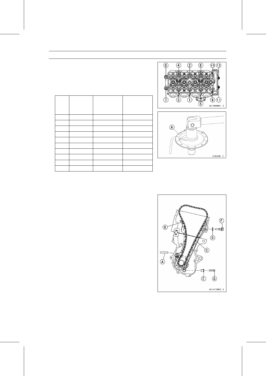
Tighten the M9 cylinder head bolts following the tightening
sequence [1

10].

First, tighten the bolts with

15 N·m (1.5 kgf·m, 11 ft·lb)

of

torque.

Next, in accordance with the following table tighten the
bolts with the specified torque. And using a torque angle
gauge [A], tighten the bolts with the specified angle.

Order

Cylinder

Head Bolts

(M9)

New Bolt

Torque N·m

(kgf·m, ft·lb)

or Angle

Used Bolt

Torque N·m

(kgf·m, ft·lb)

or Angle

1

[1]

[2]

35 (3.6, 26)

33 (3.4, 24)

2

[1]

[2]

50° ±3

50° ±3

3

[3]

[4]

35 (3.6, 26)

33 (3.4, 24)

4

[3]

[4]

50° ±3

50° ±3

5

[5]

[6]

35 (3.6, 26)

33 (3.4, 24)

6

[5]

[6]

50° ±3

50° ±3

7

[7]

[8]

30 (3.1, 22)

28 (2.9, 21)

8

[7]

[8]

50° ±3

50° ±3

9

[9]

[10]

35 (3.6, 26)

33 (3.4, 24)

10

[9]

[10]

50° ±3

50° ±3

Tighten the M6 cylinder head bolts as shown sequence
[11, 12].

Torque - Cylinder Head Bolts (M6): 12 N·m (1.2 kgf·m, 106

in·lb)

Install:

Dowel Pin [A]
Rear Camshaft Chain Guide [B]
Front Camshaft Chain Guide [C]
New O-ring [D]
Collar [E]

Tighten:

Torque - Front Camshaft Chain Guide Bolt (Upper) [F]: 25

N·m (2.5 kgf·m, 18 ft·lb)

Front Camshaft Chain Guide Bolt (Lower) [G]: 12

N·m (1.2 kgf·m, 106 in·lb)

5-28 ENGINE TOP END

Cylinder Head

Replace the washer [A] with a new one.

Tighten:

Torque - Coolant Drain Bolt (Cylinder) [B]: 9.8 N·m (1.0

kgf·m, 87 in·lb)

Install the removed parts (see appropriate chapters).

Cylinder Head Warp Inspection

Clean the cylinder head.

Lay a straightedge across the lower surface of the cylinder
head at several positions.

Use a thickness gauge [A] to measure the space between
the straightedge [B] and the head.

Cylinder Head Warp

Standard:

– – –

Service Limit: 0.05 mm (0.002 in.)

If the cylinder head is warped more than the service limit,
replace it.
If the cylinder head is warped less than the service limit,
repair the head by rubbing the lower surface on emery
paper secured to a surface plate (first No. 200, then No.
400).

ENGINE TOP END 5-29

Valves

Valve Clearance Inspection

Refer to the Valve Clearance Inspection in the Periodic
Maintenance chapter.

Valve Removal

Remove the cylinder head (see Cylinder Head Removal).

Remove the valve lifter and shim.

NOTE

Mark and record the valve lifter and shim locations so
they can be installed in their original positions.

Using the valve spring compressor assembly, remove the
valve.

Special Tools - Valve Spring Compressor Assembly [A]:

57001-241

Valve Spring Compressor Adapter,

20 [B]:

57001-1154

Valve Installation

Replace the oil seal with a new one.

Apply a thin coat of molybdenum disulfide grease to the
valve stem before valve installation.

Install the springs so that the closed coil end faces down-
wards.

Valve Stem [A]
Oil Seal [B]
Spring Seat [C]
Closed Coil End [D]
Valve Spring [E]:

EX - Purple Paint
IN - Blue Paint

Retainer [F]
Split Keepers [G]

Valve Guide Removal

Remove:

Valve (see Valve Removal)
Oil Seal
Spring Seat

Heat the area around the valve guide to 120

150°C (248

302°F), and hammer lightly on the valve guide arbor [A]

to remove the guide from the top of the head.

NOTICE

Do not heat the cylinder head with a torch. This will
warp the cylinder head. Soak the cylinder head in
oil and heat the oil.

Special Tool - Valve Guide Arbor,

4: 57001-1273

5-30 ENGINE TOP END

Valves

Valve Guide Installation

Apply engine oil to the valve guide outer surface before
installation.

Heat the area around the valve guide hole to about 120

150°C (248

302°F).

NOTICE

Do not heat the cylinder head with a torch. This Will
warp the cylinder head. Soak the cylinder head and
heat the oil.

Exhaust

Using the valve guide driver [A] and attachment [B], press
and insert the valve guide in until the attachment surface
[C] touches the head surface [D].

13.3

13.5 mm (0.52

0.53 in.) [E]

Special Tools - Valve Guide Driver: 57001-1564

Valve Guide Driver Attachment, C: 57001

-1624

Intake

Using the valve guide driver [A] and attachment [B], press
and insert the valve guide in until the attachment surface
[C] touches the head surface [D].

12.6

12.8 mm (0.496

0.504 in.) [E]

Special Tools - Valve Guide Driver: 57001-1564

Valve Guide Driver Attachment, C: 57001

-1624

Spacer: 57001-1786 [F]

Ream the valve guide with valve guide reamer [A], even
if the old guide is reused.

Special Tool - Valve Guide Reamer,

4: 57001-1274

Valve-to-Guide Clearance Measurement (Wobble
Method)

If a small bore gauge is not available, inspect the valve

guide wear by measuring the valve to valve guide clearance
with the wobble method as indicated below.

Insert a new valve [A] into the guide [B] and set a dial
gauge against the stem perpendicular to it as close as
possible to the cylinder head mating surface.

Move the stem back and forth [C] to measure valve/valve
guide clearance.

Repeat the measurement in a direction at a right angle to
the first.
If the reading exceeds the service limit, replace the guide.

ENGINE TOP END 5-31

Valves

NOTE

The reading is not actual valve/valve guide clearance
because the measuring point is above the guide.

Valve/Valve Guide Clearance (Wobble Method)

Standard:

Exhaust

0.08

0.16 mm (0.0031

0.0063 in.)

Intake

0.03

0.10 mm (0.0012

0.0039 in.)

Service Limit:

Exhaust

0.36 mm (0.014 in.)

Intake

0.30 mm (0.012 in.)

Valve Seat Inspection

Remove the valve (see Valve Removal).

Check the valve seating surface [A] between the valve [B]
and valve seat [C].

Measure the outside diameter [D] of the seating pattern
on the valve seat.
If the outside diameter is too large or too small, repair the
seat (see Valve Seat Repair).

Valve Seating Surface Outside Diameter

Standard:

Exhaust 22.8

23.0 mm (0.898

0.906 in.)

Intake

26.93

27.13 mm (1.060

1.068 in.)

Measure the seat width [E] of the portion where there is
no build-up carbon (white portion) of the valve seat with a
vernier caliper.

Good [F]

If the width is too wide [G], too narrow [H] or uneven [J],
repair the seat (see Valve Seat Repair).

Valve Seating Surface Width

Standard:

Exhaust 0.8

1.2 mm (0.031

0.047 in.)

Intake

0.5

1.0 mm (0.020

0.039 in.)

Valve Seat Repair

Repair the valve seat with the valve seat cutters [A].

Special Tools - Valve Seat Cutter Holder Bar [B]: 57001

-1128

Valve Seat Cutter Holder,

4 [C]: 57001-1275

[For Exhaust Valve Seat]

Valve Seat Cutter, 45° -

24.5: 57001-1113

Valve Seat Cutter, 32° -

25: 57001-1118

Valve Seat Cutter, 60° -

25: 57001-1328

[For Intake Valve Seat]

Valve Seat Cutter, 45° -

30: 57001-1187

Valve Seat Cutter, 32° -

30: 57001-1120

Valve Seat Cutter, 60° -

27: 57001-1409

If the manufacturer’s instructions are not available, use
the following procedure.

5-32 ENGINE TOP END

Valves

Seat Cutter Operation Care

1. This valve seat cutter is developed to grind the valve for

repair. Therefore the cutter must not be used for other
purposes than seat repair.

2. Do not drop or shock the valve seat cutter, or the dia-

mond particles may fall off.

3. Do not fail to apply engine oil to the valve seat cutter

before grinding the seat surface. Also wash off ground
particles sticking to the cutter with washing oil.

NOTICE

Do not use a wire brush to remove the metal par-
ticles from the cutter. It will take off the diamond
particles.

4. Setting the valve seat cutter holder in position, operate

the cutter in one hand. Do not apply too much force to
the diamond portion.

NOTE

Prior to grinding, apply engine oil to the cutter and dur-
ing the operation, wash off any ground particles sticking
to the cutter with washing oil.

5. After use, wash it with washing oil and apply thin layer

of engine oil before storing.

Marks Stamped on the Cutter

The marks stamped on the back of the cutter [A] represent

the following.
60° ........................... Cutter angle [B]
37.5

....................... Outer diameter of cutter [C]

Operating Procedures

Clean the seat area carefully.

Coat the seat with machinist’s dye.

Fit a 45° cutter into the holder and slide it into the valve
guide.

Press down lightly on the handle and turn it right or left.
Grind the seating surface only until it is smooth.

NOTICE

Do not grind the seat too much. Overgrinding will
reduce valve clearance by sinking the valve into the
head. If the valve sinks too far into the head, it will
be impossible to adjust the clearance, and the cylin-
der head must be replaced.

ENGINE TOP END 5-33

Valves

Measure the outside diameter of the seating surface with
a vernier caliper.
If the outside diameter of the seating surface is too small,
repeat the 45° grind until the diameter is within the spec-
ified range.

Widened Width [A] of engagement by machining with
45° cutter
Ground Volume [B] by 32° cutter
32° [C]
Correct Width [D]
Ground Volume [E] by 60° cutter
60° [F]

Measure the outside diameter of the seating surface with
a vernier caliper.
If the outside diameter of the seating surface is too small,
repeat the 45° [A] grind until the diameter is within the
specified range.

Original Seating Surface [B]

NOTE

Remove all pittings of flaws from 45° ground surface.

After grinding with 45° cutter, apply thin coat of machin-
ist’s dye to seating surface. This makes seating surface
distinct and 32° and 60° grinding operation easier.

When the valve guide is replaced, be sure to grind with
45° cutter for centering and good contact.

If the outside diameter [A] of the seating surface is too
large, make the 32° [B] grind described below.
If the outside diameter of the seating surface is within the
specified range, measure the seat width as described be-
low.

Grind the seat at a 32° angle until the seat outside diam-
eter is within the specified range.

To make the 32° grind, fit a 32° cutter into the holder, and
slide it into the valve guide.

Turn the holder one turn at a time while pressing down
very lightly. Check the seat after each turn.

NOTICE

The 32° cutter removes material very quickly.
Check the seat outside diameter frequently to pre-
vent overgrinding.

After making the 32° grind, return to the seat outside di-
ameter measurement step above.

To measure the seat width, use a vernier caliper to mea-
sure the width of the 45° angle portion of the seat at sev-
eral places around the seat.
If the seat width is too narrow, repeat the 45° grind until
the seat is slightly too wide, and then return to the seat
outside diameter measurement step above.

5-34 ENGINE TOP END

Valves

If the seat width is too wide, make the 60° [A] grind de-
scribed below.
If the seat width is within the specified range, lap the valve
to the seat as described below.

Grind the seat at a 60° angle until the seat width is within
the specified range.

To make the 60° grind, fit 60° cutter into the holder, and
slide it into the valve guide.

Turn the holder, while pressing down lightly.

After making the 60° grind, return to the seat width mea-
surement step above.

Correct Width [B]

Lap the valve to the valve seat, once the seat width and
outside diameter are within the ranges specified above.

Put a little coarse grinding compound on the face of the
valve in a number of places around the valve head.

Spin the valve against the seat until the grinding com-
pound produces a smooth, matched surface on both the
seat and the valve.

Repeat the process with a fine grinding compound.

Lapper [A]
Valve Seat [B]
Valve [C]

The seating area should be marked about in the middle
of the valve face.
If the seat area is not in the right place on the valve, check
to be sure the valve is the correct part. If it is, it may have
been refaced too much; replace it.

Be sure to remove all grinding compound before assem-
bly.

When the engine is assembled, be sure to adjust the valve
clearance (see Valve Clearance Inspection in the Periodic
Maintenance chapter).

ENGINE TOP END 5-35

Valves

5-36 ENGINE TOP END

Throttle Body Assy Holder

Throttle Body Assy Holder Removal

Remove:

Throttle Body Assy (see Throttle Body Assy Removal in
the Fuel System (DFI) chapter)
Clamps [A]
Throttle Body Assy Holder Bolts [B]
Throttle Body Assy Holders [C]

Throttle Body Assy Holder Installation

Replace the O-rings [A] with new ones.

Apply liquid gasket to any three positions of the O-rings
to prevent it from coming off, and install them.

Sealant - Liquid Gasket, TB1211F: 92104-0004

Install the holders [B] as shown.

Recession [C]

Apply a non-permanent locking agent to the threads of
the throttle body assy holder bolts [D], and tighten them.

Torque - Throttle Body Assy Holder Bolts: 12 N·m (1.2

kgf·m, 106 in·lb)

Fit the hole of the clamp [A] to the projection [B] of the
holder [C].

25° [D]
10° [E]

Install:

Throttle Body Assy (see Throttle Body Assy Installation
in the Fuel System (DFI) chapter)

ENGINE TOP END 5-37

Muffler

WARNING

The muffler can become extremely hot during nor-
mal operation and cause severe burns. Do not re-
move the muffler while it is hot.

Muffler Body Removal

Remove the lower ends of the exhaust butterfly valve ca-
bles from the pulley of the muffler body (see Exhaust But-
terfly Valve Cable Removal).

Loosen the muffler body clamp bolt [A].

Remove the muffler body mounting bolt [B], and pull out
the muffler body [C] backward from the premuffler cham-
ber.

5-38 ENGINE TOP END

Muffler

Muffler Body Installation

Replace the premuffler chamber gasket [A] with a new
one.

Install the muffler body gasket to the premuffler chamber
[B] until it is bottomed so that the chamfer side [C] faces
muffler body [D].

About 4.0 mm (0.16 in.) [E]

Install the muffler body clamp [F] as shown.

Insert the projection [G] into the slot [H].

Replace the muffler body mounting nut [I].

Install the muffler body.

Tighten the muffler body mounting bolt [J] and muffler
body clamp bolt [K].

Torque - Muffler Body Mounting Bolt: 25 N·m (2.5 kgf·m, 18

ft·lb)

Install the lower ends of the exhaust butterfly valve ca-
bles, and adjust the cables correctly (see Exhaust Butter-
fly Valve Cable Installation).

Thoroughly warm up the engine, wait until the engine
cools down, retighten all the bolts.

Install the removed parts (see appropriate chapters).

ENGINE TOP END 5-39

Muffler

Premuffler Chamber Removal

Remove:

Muffler Body (see Muffler Body Removal)
Cotter Pin [A]

Loosen the rear axle nut [B].

Loosen the both chain adjuster locknuts [C].

Remove the drive chain from the rear sprocket.

Pull the rear wheel backward.

Remove:

Guard Bolts [A]
Premuffler Chamber Guard [B]

Loosen the exhaust pipe clamp bolt [A].

Remove the bolts [B].

Pull out the premuffler chamber backward from the ex-
haust pipe.

5-40 ENGINE TOP END

Muffler

Premuffler Chamber Installation

Replace the exhaust pipe gasket [A] with a new one.

Install the exhaust pipe gasket to the exhaust pipe [B] until
it is bottomed so that the chamfer side [C] faces premuffler
chamber [D].

About 4.0 mm (0.16 in.) [E]

Install the exhaust pipe clamp [F] as shown.

Insert the projection [G] into the slot [H].

Install the premuffler chamber and bracket [I].

Tighten the premuffler chamber mounting bolt [J], bracket
bolt [K] and exhaust pipe clamp bolt [L] securely.

Torque - Premuffler Chamber Mounting Bolt: 40 N·m (4.1

kgf·m, 30 ft·lb)

Premuffler Chamber Bracket Bolt: 40 N·m (4.1

kgf·m, 30 ft·lb)

Install the premuffler chamber guard [M], and tighten the
guard bolt [N].

Install the removed parts (see appropriate chapters).

Thoroughly warm up the engine, wait until the engine
cools down, retighten all the bolts.

ENGINE TOP END 5-41

Muffler

Exhaust Pipe Removal

Remove:

Radiator (see Radiator and Radiator Fan Removal in the
Cooling System chapter)
Oxygen Sensor (Equipped Models) (see Oxygen Sen-
sor Removal (Equipped Models) in the Electrical System
chapter)
Exhaust Pipe Clamp Bolt [A]

Remove the exhaust pipe holder nuts [A], and pull out the
exhaust pipe forward from the premuffler chamber.

5-42 ENGINE TOP END

Muffler

Exhaust Pipe Installation

Replace the exhaust pipe gaskets [A] [B] with new ones.

Install the exhaust pipe gasket [B] to the exhaust pipe
[C] until it is bottomed so that the chamfer side [D] faces
premuffler chamber [E].

About 4.0 mm (0.16 in.) [F]

Install the exhaust pipe clamp [G] as shown.

Insert the projection [H] into the slot [I].

Install the exhaust pipe.

Turn the [UP] mark to the top of the exhaust pipe holders
[J].

Tighten the following bolt and nuts securely.

Exhaust Pipe Holder Nuts [K]
Exhaust Pipe Clamp Bolt [L]

Install the removed parts (see appropriate chapters).

Thoroughly warm up the engine, wait until the engine
cools down, retighten all the bolts and nuts.

ENGINE TOP END 5-43

Muffler

Exhaust Butterfly Valve Cable Removal

Remove the front seat (see Front Seat Removal in the
Frame chapter).

Open the clamp [A] and free the cables.

Slide the dust cover [B].

Loosen the locknut [A], and turn the adjuster [B] to give
the cable plenty of play.

Remove the upper ends [A] of the exhaust butterfly valve
cables from the pulley [B].

Remove:

Bolts [A]

Remove the muffler body cover [B] forward from the muf-
fler body [C].

Loosen the locknuts [A].

Remove the lower ends [B] of the exhaust butterfly valve
cables from the pulley [C].

Pull the exhaust butterfly valve cables out of the frame.

5-44 ENGINE TOP END

Muffler

Exhaust Butterfly Valve Cable Installation

Confirm whether pulley [A] is an angle shown.

41.7° ±7° [B]

This position is original position of the pulley.

NOTE

Correct the position electrically after confirming use is
discontinued and there is no damage when differing
from the angle of shown.

NOTICE

Do not correct the pulley position with the tool,
forcibly. The actuator damage will occur.

If the angle is wrong, adjust the pulley (see Exhaust But-
terfly Valve Actuator Installation in the Self-Diagnosis Sys-
tem chapter).

Run the exhaust butterfly valve cables correctly (see
Cable, Wire, and Hose Routing section in the Appendix
chapter).

Install the lower ends of the exhaust butterfly valve cables
to the pulley of the muffler body as shown.

Open Cable [A] (White Locknut)
Close Cable [B] (Black Locknut)

Tighten:

Torque - Exhaust Butterfly Valve Cable Locknuts [C]: 5.0

N·m (0.51 kgf·m, 44 in·lb)

Fit the slot [A] of the muffler cover [B] to the damper [C]
of the muffler body, and tighten the bolts.

ENGINE TOP END 5-45

Muffler

Install the upper ends of the exhaust butterfly valve ca-
bles to the pulley of the exhaust butterfly valve actuator,
following the specified installing sequence.

First, install the close cable (black) [A].

Second, install the open cable (white) [B].

Third, stretch the open cable (white) by using the adjuster
[C].

Turn the adjuster counterclockwise until the play of the
open cable becomes no play.

Fourth, turn the adjuster of the open cable clockwise by
1/2 to 1 rotation.

Lastly, tighten the adjuster locknut of the open cable se-
curely.

After installation, cover the dust cover on the adjuster as
shown.

15 mm (0.59 in.) or less [D]

Fix the exhaust butterfly valve cables with the clamp [E].

After connecting the cables, turn the ignition switch on
and make sure that the pulley turns clockwise and coun-
terclockwise, then it returns clockwise slightly.

CLUTCH 6-1

6

Clutch

Table of Contents

Exploded View........................................................................................................................

6-2

Specifications .........................................................................................................................

6-4

Special Tool and Sealant ........................................................................................................

6-5

Clutch Lever and Cable ..........................................................................................................

6-6

Clutch Lever Free Play Inspection ....................................................................................

6-6

Clutch Lever Free Play Adjustment ..................................................................................

6-6

Cable Removal .................................................................................................................

6-6

Cable Installation ..............................................................................................................

6-6

Cable Lubrication ..............................................................................................................

6-6

Clutch Lever Installation....................................................................................................

6-6

Clutch Cover...........................................................................................................................

6-7

Clutch Cover Removal ......................................................................................................

6-7

Clutch Cover Installation ...................................................................................................

6-7

Release Shaft Removal ....................................................................................................

6-7

Release Shaft Installation .................................................................................................

6-8

Clutch Cover Disassembly................................................................................................

6-8

Clutch Cover Assembly.....................................................................................................

6-9

Clutch .....................................................................................................................................

6-10

Clutch Removal.................................................................................................................

6-10

Clutch Installation..............................................................................................................

6-11

Clutch Plate Assembly Length Measurement ...................................................................

6-15

Clutch Plate, Wear, Damage Inspection ...........................................................................

6-15

Clutch Plate Warp Inspection............................................................................................

6-15

Clutch Spring Free Length Measurement .........................................................................

6-16

Clutch Housing Finger Inspection .....................................................................................

6-16

Clutch Housing Spline Inspection .....................................................................................

6-16

Clutch Pressure Plate and Clutch Hub Inspection ............................................................

6-16

6-2 CLUTCH

Exploded View

CLUTCH 6-3

Exploded View

Torque

No.

Fastener

N·m

kgf·m

ft·lb

Remarks

1

Clutch Lever Clamp Bolts

7.8

0.80

69 in·lb

S

2

Clutch Hub Nut

135

13.8

100

R

3

Clutch Stopper Bolts

8.8

0.90

78 in·lb

4

Clutch Cover Bolts (M6, L = 40 mm)

9.8

1.0

87 in·lb

5

Oil Filler Plug

Hand-tighten

6

Clutch Cover Bolts (M6, L = 25 mm)

9.8

1.0

87 in·lb

CL: Apply cable lubricant.

EO: Apply engine oil.

G: Apply grease.

L: Apply a non-permanent locking agent.

M: Apply molybdenum disulfide grease.

R: Replacement Parts

S: Follow the specified tightening sequence.

W: Apply water.

6-4 CLUTCH

Specifications

Item

Standard

Service Limit

Clutch Lever Free Play

2

3 mm (0.08

0.12 in.)

– – –

Clutch

Clutch Plate Assembly Length

40.5

41.3 mm (1.59

1.63 in.)

– – –

Friction Plate Thickness

2.72

2.88 mm (0.107

0.113 in.)

2.5 mm (0.098 in.)

Friction and Steel Plate Warp

0.15 mm (0.0059 in.) or less

0.3 mm (0.012 in.)

Clutch Spring Free Length

48.38 mm (1.905 in.)

46.3 mm (1.82 in.)

CLUTCH 6-5

Special Tool and Sealant

Clutch Holder:
57001-1243

Crankcase Splitting Tool Assembly:
57001-1362

Clutch Plate Holder:
57001-1788

Liquid Gasket, TB1211F:
92104-0004

6-6 CLUTCH

Clutch Lever and Cable

Clutch Lever Free Play Inspection

Refer to the Clutch Operation Inspection in the Periodic
Maintenance chapter.

Clutch Lever Free Play Adjustment

Refer to the Clutch Operation Inspection in the Periodic
Maintenance chapter.

Cable Removal

Remove:

Air Cleaner Housing (see Air Cleaner Housing Removal
in the Fuel System (DFI) chapter)

Slide the dust cover [A] at the clutch cable lower end out
of place.

Loosen the nuts [B], and slide the lower end of the clutch
cable to give the cable plenty of play.

Screw in the adjuster [A].

Line up the slots [B] in the clutch lever and adjuster, and
then free the cable from the lever.

Free the clutch inner cable tip from the clutch release
lever.

Remove the clutch cable out of the frame.

Cable Installation

Run the clutch cable correctly (see Cable, Wire, and Hose
Routing section in the Appendix chapter).

Adjust the clutch cable (see Clutch Operation Inspection
in the Periodic Maintenance chapter).

Install the removed parts (see appropriate chapters).

Cable Lubrication

Refer to the Chassis Parts Lubrication in the Periodic
Maintenance chapter.

Clutch Lever Installation

Install the clutch lever so that the mating surface [A] of the
clutch lever clamp is aligned with the punch mark [B] of
the handlebar.

Tighten the upper clamp bolt first, and then the lower
clamp bolt.

There will be a gap at the lower part of the clamp after
tightening.

Torque - Clutch Lever Clamp Bolts: 7.8 N·m (0.80 kgf·m, 69

in·lb)

CLUTCH 6-7

Clutch Cover

Clutch Cover Removal

Drain the engine oil (see Engine Oil Change in the Peri-
odic Maintenance chapter).

Remove:

Right Lower Fairing (see Lower Fairing Removal in the
Frame chapter)
Clutch Cable Lower End [A] (see Cable Removal)
Clutch Cover Bolts [B]
Bracket [C]

Turn the release lever [A] counterclockwise as shown,
and remove the clutch cover [B].

About 90° [C]

Clutch Cover Installation

Using a cleaning fluid, clean off any oil or dirt that may be
on the liquid gasket coating area. Dry them with a clean
cloth

Apply liquid gasket to the area [A] where the mating sur-
face of the crankcase touches the clutch cover gasket.

Sealant - Liquid Gasket, TB1211F: 92104-0004

Be sure that the dowel pins [B] are in position.

Replace the clutch cover gasket with a new one.

Install the bracket [A].

Tighten:

Torque - Clutch Cover Bolts: 9.8 N·m (1.0 kgf·m, 87 in·lb)

L = 40 mm (1.57 in.) [B]

L = 25 mm (0.98 in.) [C]

Release Shaft Removal

NOTICE

Do not remove the clutch release lever and shaft
assembly unless it is absolutely necessary. If re-
moved, the oil seal replacement may be required.

Remove the clutch cover (see Clutch Cover Removal).

Pull the release lever and shaft assembly [A] straight out
of the clutch cover.

6-8 CLUTCH

Clutch Cover

Release Shaft Installation

Apply grease to the oil seal lips on the upper ridge of the
clutch cover.

Apply engine oil to the needle bearings in the hole of the
clutch cover.

Apply molybdenum disulfide grease to the pusher-holding
portion [A] on the release shaft.

Install the washer [B] and spring [C].

Insert the release shaft straight into the upper hole of the
clutch cover.

NOTICE

When inserting the release shaft, be careful not to
remove the spring of the oil seal.

Fit the spring [A] as shown.

Clutch Cover Disassembly

Remove:

Clutch Cover (see Clutch Cover Removal)
Release Lever and Shaft Assembly (see Release Shaft
Removal)
Oil Seal [A]
Oil Filler Plug [B]

Remove:

Needle Bearings [A]
Oil Level Inspection Window [B]

CLUTCH 6-9

Clutch Cover

Clutch Cover Assembly

Replace the needle bearings and oil seal with new ones.

NOTE

Install the needle bearings so that the manufacture’s
mark face out.

Install the needle bearings [A] and oil seal [B] position as
shown.

Press the lower bearing, do not protrude from the boss
[C] of the clutch cover.

Press the upper bearing so that the bearing surface [D] is
flush with the housing end of clutch cover [E].

Press the oil seal until the bottom.

Apply grease to the oil seal lips.

Apply water to the rubber portion [A] of the oil level in-
spection window.

Press the oil level inspection window so that its projection
[B] faces inside of the clutch cover [C].

Replace the O-ring [A] of the oil filler plug [B] with a new
one.

Apply grease to the new O-ring.

Tighten:

Torque - Oil Filler Plug: Hand-tighten

6-10 CLUTCH

Clutch

Clutch Removal

Remove:

Clutch Cover (see Clutch Cover Removal)
Starter Clutch Bolt Cap [A]

Using a wrench on the starter clutch bolt, turn the crank-
shaft clockwise until the clutch stopper bolts [A] reaches
the position as shown.

Set the special tools as shown to hold the clutch stopper
plate.

Special Tools - Crankcase Splitting Tool Assembly [A]:

57001-1362

Clutch Plate Holder [B]: 57001-1788

128 mm [C] (57001-1362)
139 mm [D] (57001-1788)
173 mm [E] (57001-1788)

Screw the center bolt [F] of the crankcase splitting tool
assembly tightly.

Remove the clutch stopper bolts [A].

Remove the crankcase splitting tool assembly and clutch
plate holder.

Remove:

Clutch Stopper Plate
Clutch Springs

Remove:

Clutch Pressure Plate [A] (with Shim, Bearing, Pusher
[B], Spring and Washer)
Friction Plates and Steel Plates

CLUTCH 6-11

Clutch

Hold the sub clutch hub [A] steady with the clutch holder
[B], and remove the nut [C] and washers.

Special Tool - Clutch Holder: 57001-1243

Use the clutch holder with sharpened hook nose by grind-
ing.

Special Tool - Clutch Holder: 57001-1243

Grind the hook nose by 0.5 mm (0.02 in.) as shown.

Remove:

Clutch Hub [A]
Spacer [B]

Using the two 4 mm (0.16 in.) bolts [A], pull out the sleeve
[B], needle bearing [C] and clutch housing [D].

Remove the spacer.

Clutch Installation

Install the spacer [A] so that the stepped side [B] faces
inward.

6-12 CLUTCH

Clutch

Engage the clutch housing gear [A] and oil pump drive
gear [B] with the crankshaft primary gear [C] and oil pump
drive gear [D].

Apply engine oil to the sleeve [A] and needle bearing [B].

Install:

Needle Bearing
Sleeve
Spacer [C]

Install:

Clutch Hub [A]
Washer [B]

Install the washer [C] so that the “OUT SIDE” mark faces
outward.

Replace the clutch hub nut [A] with a new one.

Hold the sub clutch hub [B] steady with the clutch holder
[C], and tighten the clutch hub nut.

Special Tool - Clutch Holder: 57001-1243

Torque - Clutch Hub Nut: 135 N·m (13.8 kgf·m, 100 ft·lb)


Content      ..     6      7      8      9     ..