Kawasaki Motorcycle Ninja ZX-6R / Ninja ZX-6R ABS. Service Manual (2013 year) - page 7
 

  Index      Manuals     Kawasaki Motorcycle Ninja ZX-6R / Ninja ZX-6R ABS. Service Manual (2013 year)


Search            copyright infringement  


Content      ..     5      6      7      8     ..


Kawasaki Motorcycle Ninja ZX-6R / Ninja ZX-6R ABS. Service Manual (2013 year) - page 7


COOLING SYSTEM 4-15

Radiator

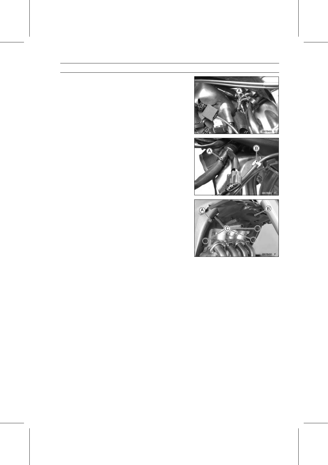
Heat Insulation Plate Removal

Remove:

Radiator (see Radiator and Radiator Fan Removal)

Open the clamps [A].

Open the clamp [A].

Free the lead from the clamp [B].

Free the right switch housing lead and front wheel rotation
sensor lead from the clamp on the right side of the heat
insulation plate.

Remove:

Heat Insulation Plate Bolt [A]
Heat Insulation Plate [B]

Clear the projections [C] from the frame.

Heat Insulation Plate Installation

Installation is the reverse of removal.

Apply a non-permanent locking agent to the threads of
the heat insulation plate bolt and tighten it.

Torque - Heat insulation Plate Bolt: 3.9 N·m (0.40 kgf·m, 35

in·lb)

Run the leads correctly (see Cable, Wire, and Hose Rout-
ing section in the Appendix chapter).

4-16 COOLING SYSTEM

Thermostat

Thermostat Removal

Remove the oil cooler (see Oil Cooler Removal in the En-
gine Lubrication System chapter)

Loosen the water hose clamp screw [A].

Disconnect the water hose [B].

Remove:

Thermostat Housing Cover Bolts [C]
Thermostat Housing Cover [D]
Thermostat

Thermostat Installation

Install the thermostat [A] in the housing so that the air
bleeder hole [B] is on top.

Replace the O-ring [A] with a new one.

Apply liquid gasket to any three positions of the new O
-ring to prevent it from coming off.

Sealant - Liquid Gasket, TB1211F: 92104-0004

Install a new O-ring into the thermostat housing cover [B].

Tighten:

Torque - Thermostat Housing Cover Bolts [C]: 5.9 N·m

(0.60 kgf·m, 52 in·lb)

Confirm that the thermostat is installed correctly.

Install the water hose and tighten the clamp (see Cable,
Wire, and Hose Routing section in the Appendix chapter).

Torque - Water Hose Clamp Screw: 3.0 N·m (0.31 kgf·m, 27

in·lb)

Install the removed parts (see appropriate chapters).

Thermostat Inspection

Remove the thermostat (see Thermostat Removal).

Inspect the thermostat valve [A] at room temperature.
If the valve is open, replace the thermostat with a new
one.

COOLING SYSTEM 4-17

Thermostat

To check valve opening temperature, suspend the ther-
mostat [A] in a container of water and raise the tempera-
ture of the water.

The thermostat must be completely submerged and must
not touch the container sides or bottom. Suspend an ac-
curate thermometer [B] in the water so that the heat sen-
sitive portions [C] are located in almost the same depth.
It must not touch the container, either.
If the measurement is out of the specified range, replace
the thermostat with a new one.

Thermostat Valve Opening Temperature

58

62°C (136

144°F)

4-18 COOLING SYSTEM

Hoses and Pipes

Hose Installation

Install the hoses and pipes, being careful to follow bend-
ing direction. Avoid sharp bending, kinking, flattening or
twisting.

Run the hoses (see Cable, Wire, and Hose Routing sec-
tion in the Appendix chapter).

Install the clamp [A] as near as possible to the hose end
to clear the raised rib of the fitting. This will prevent the
hoses from working loose.

The clamp screws should be positioned correctly to pre-
vent the clamps from contacting the other parts.

Tighten:

Torque - Water Hose Clamp Screws: 3.0 N·m (0.31 kgf·m,

27 in·lb)

Hose Inspection

Refer to the Radiator Hose and Pipe Inspection in the
Periodic Maintenance chapter.

COOLING SYSTEM 4-19

Water Temperature Sensor

Water Temperature Sensor Removal/Installation

Refer to the Water Temperature Sensor Removal/Instal-
lation in the Self-Diagnosis System chapter.

Water Temperature Sensor Inspection

Refer to the Water Temperature Sensor Inspection in the
Electrical System chapter.

ENGINE TOP END 5-1

5

Engine Top End

Table of Contents

Exploded View...................................

5-2

Exhaust System Identification ...........

5-6

Specifications ....................................

5-8

Special Tools and Sealant .................

5-9

Clean Air System...............................

5-11

Air Suction Valve Removal...........

5-11

Air Suction Valve Installation........

5-11

Air Suction Valve Inspection ........

5-12

Air Switching Valve Removal .......

5-12

Air Switching Valve Installation ....

5-12

Air Switching Valve Operation

Test............................................

5-13

Air Switching Valve Unit Test .......

5-13

Clean Air System Hose

Inspection..................................

5-13

Cylinder Head Cover .........................

5-14

Cylinder Head Cover Removal ....

5-14

Cylinder Head Cover Installation .

5-14

Camshaft Chain Tensioner ................

5-16

Camshaft Chain Tensioner

Removal ....................................

5-16

Camshaft Chain Tensioner

Installation .................................

5-17

Camshaft, Camshaft Chain ...............

5-18

Camshaft Removal ......................

5-18

Camshaft Installation ...................

5-19

Camshaft, Camshaft Cap Wear

Inspection..................................

5-23

Camshaft Runout Inspection........

5-24

Cam Wear Inspection ..................

5-24

Camshaft Chain Removal ............

5-24

Cylinder Head....................................

5-25

Cylinder Compression

Measurement ............................

5-25

Cylinder Head Removal ...............

5-26

Cylinder Head Installation ............

5-26

Cylinder Head Warp Inspection ...

5-28

Valves ................................................

5-29

Valve Clearance Inspection .........

5-29

Valve Removal .............................

5-29

Valve Installation ..........................

5-29

Valve Guide Removal ..................

5-29

Valve Guide Installation ...............

5-30

Valve-to-Guide Clearance

Measurement (Wobble
Method) .....................................

5-30

Valve Seat Inspection ..................

5-31

Valve Seat Repair ........................

5-31

Throttle Body Assy Holder.................

5-36

Throttle Body Assy Holder

Removal ....................................

5-36

Throttle Body Assy Holder

Installation .................................

5-36

Muffler................................................

5-37

Muffler Body Removal..................

5-37

Muffler Body Installation...............

5-38

Premuffler Chamber Removal .....

5-39

Premuffler Chamber Installation ..

5-40

Exhaust Pipe Removal.................

5-41

Exhaust Pipe Installation..............

5-42

Exhaust Butterfly Valve Cable

Removal ....................................

5-43

Exhaust Butterfly Valve Cable

Installation .................................

5-44

5-2 ENGINE TOP END

Exploded View

ENGINE TOP END 5-3

Exploded View

Torque

No.

Fastener

N·m

kgf·m

ft·lb

Remarks

1

Air Suction Valve Cover Bolts

9.8

1.0

87 in·lb

L

2

Cylinder Head Cover Bolts

9.8

1.0

87 in·lb

S

3

Spark Plugs

13

1.3

115 in·lb

4

Breather Hose Fitting

15

1.5

11

L

5

Camshaft Sprocket Bolts

15

1.5

11

L

6

Camshaft Cap Bolts

12

1.2

106 in·lb

S

7

Upper Camshaft Chain Guide Bolts

12

1.2

106 in·lb

S

8

Front Camshaft Chain Guide Bolt (Upper)

25

2.5

18

9

Cylinder Head Bolts (M9)

see the

text

MO, S

10 Water Passage Plugs

19.6

2.00

14.5

L

11 Cylinder Head Bolts (M6)

12

1.2

106 in·lb

S

12 Throttle Body Assy Holder Bolts

12

1.2

106 in·lb

L

13 Throttle Body Assy Holder Clamp Bolts

2.9

0.30

26 in·lb

14 Front Camshaft Chain Guide Bolt (Lower)

12

1.2

106 in·lb

15 Camshaft Chain Tensioner Cap Bolt

20

2.0

15

16 Camshaft Chain Tensioner Mounting Bolts

11

1.1

97 in·lb

17 Coolant Drain Bolt (Cylinder)

9.8

1.0

87 in·lb

18 Starter Clutch Bolt Cap

2.9

0.30

26 in·lb

19 Timing Inspection Cap

2.9

0.30

26 in·lb

G: Apply grease.

L: Apply a non-permanent locking agent.

LG: Apply liquid gasket.

M: Apply molybdenum disulfide grease.

MO: Apply molybdenum disulfide oil solution.

(mixture of the engine oil and molybdenum disulfide grease in a weight ratio 10:1)

R: Replacement Parts

S: Follow the specified tightening sequence.

5-4 ENGINE TOP END

Exploded View

ENGINE TOP END 5-5

Exploded View

Torque

No.

Fastener

N·m

kgf·m

ft·lb

Remarks

1

Exhaust Butterfly Valve Actuator Pulley Bolt

4.9

0.50

43 in·lb

2

Exhaust Butterfly Valve Actuator Mounting
Screws

4.3

0.44

38 in·lb

3

Muffler Body Mounting Bolt

25

2.5

18

4

Muffler Body End Cover Bolts

7.0

0.71

62 in·lb

L

5

Premuffler Chamber Mounting Bolt

40

4.1

30

6

Premuffler Chamber Bracket Bolt

40

4.1

30

7

Exhaust Butterfly Valve Cable Locknuts

5.0

0.51

44 in·lb

L: Apply a non-permanent locking agent.

R: Replacement Parts

5-6 ENGINE TOP END

Exhaust System Identification

Exhaust Pipe Mark Position [A]

Premuffler Chamber Mark Position [A]

ENGINE TOP END 5-7

Exhaust System Identification

Muffler Body Mark Position [A]

Exhaust Pipe [A] with Hole [B] for Oxygen Sensor [C]

Honeycomb Type Catalyst Positions [A]

5-8 ENGINE TOP END

Specifications

Item

Standard

Service Limit

Camshafts

Cam Height:

Exhaust

33.343

33.457 mm (1.3127

1.3172 in.)

33.24 mm (1.309 in.)

Intake

34.743

34.857 mm (1.3678

1.3723 in.)

34.64 mm (1.364 in.)

Camshaft Journal/Camshaft
Cap Clearance

0.038

0.081 mm (0.0015

0.0032 in.)

0.17 mm (0.0067 in.)

Camshaft Journal Diameter

23.940

23.962 mm (0.9425

0.9434 in.)

23.91 mm (0.941 in.)

Camshaft Bearing Inside
Diameter

24.000

24.021 mm (0.9449

0.9457 in.)

24.08 mm (0.948 in.)

Camshaft Runout

TIR 0.02 mm (0.0008 in.) or less

TIR 0.1 mm (0.004 in.)

Cylinder Head

Cylinder Compression

(Usable Range)

1 050

1 598 kPa (10.7

16.3 kgf/cm²,

– – –

152

232 psi) at 300 r/min (rpm)

Cylinder Head Warp

– – –

0.05 mm (0.002 in.)

Valves

Valve Clearance:

Exhaust

0.24

0.31 mm (0.0094

0.0122 in.)

– – –

Intake

0.13

0.19 mm (0.0051

0.0075 in.)

– – –

Valve Head Thickness:

Exhaust

1.0 mm (0.039 in.)

0.5 mm (0.020 in.)

Intake

0.5 mm (0.020 in.)

0.3 mm (0.012 in.)

Valve Stem Bend

TIR 0.01 mm (0.0004 in.) or less

TIR 0.05 mm (0.002 in.)

Valve Stem Diameter:

Exhaust

3.955

3.970 mm (0.1557

0.1563 in.)

3.94 mm (0.155 in.)

Intake

3.975

3.990 mm (0.1565

0.1571 in.)

3.96 mm (0.156 in.)

Valve Guide Inside Diameter:

Exhaust

4.000

4.012 mm (0.1575

0.1580 in.)

4.08 mm (0.161 in.)

Intake

4.000

4.012 mm (0.1575

0.1580 in.)

4.08 mm (0.161 in.)

Valve/Valve Guide
Clearance (Wobble Method):

Exhaust

0.08

0.16 mm (0.0031

0.0063 in.)

0.36 mm (0.014 in.)

Intake

0.03

0.10 mm (0.0012

0.0039 in.)

0.30 mm (0.012 in.)

Valve Seat Cutting Angle

32°, 45°, 60°

– – –

Valve Seating Surface:

Width:

Exhaust

0.8

1.2 mm (0.031

0.047 in.)

– – –

Intake

0.5

1.0 mm (0.020

0.039 in.)

– – –

Outside Diameter:

Exhaust

22.8

23.0 mm (0.898

0.906 in.)

– – –

Intake

26.93

27.13 mm (1.060

1.068 in.)

– – –

Valve Spring Free Length:

Exhaust

41.01 mm (1.615 in.)

40.2 mm (1.583 in.)

Intake

39.99 mm (1.574 in.)

39.0 mm (1.535 in.)

ENGINE TOP END 5-9

Special Tools and Sealant

Compression Gauge, 20 kgf/cm²:
57001-221

Valve Spring Compressor Assembly:
57001-241

Valve Seat Cutter, 45° -

24.5:

57001-1113

Valve Seat Cutter, 32° -

25:

57001-1118

Valve Seat Cutter, 32° -

30:

57001-1120

Valve Seat Cutter Holder Bar:
57001-1128

Valve Spring Compressor Adapter,

20:

57001-1154

Valve Seat Cutter, 45° -

30:

57001-1187

Valve Guide Arbor,

4:

57001-1273

Valve Guide Reamer,

4:

57001-1274

5-10 ENGINE TOP END

Special Tools and Sealant

Valve Seat Cutter Holder,

4:

57001-1275

Valve Seat Cutter, 60° -

25:

57001-1328

Valve Seat Cutter, 60° -

27:

57001-1409

Valve Guide Driver:
57001-1564

Compression Gauge Adapter, M10 × 1.0:
57001-1601

L-Shape Hose:
57001-1606

Valve Guide Driver Attachment, C:
57001-1624

Spacer:
57001-1786

Liquid Gasket, TB1211F:
92104-0004

Liquid Gasket, TB1216B:
92104-1064

ENGINE TOP END 5-11

Clean Air System

Air Suction Valve Removal

Remove:

Air Switching Valve (see Air Switching Valve Removal)
Air Suction Valve Cover Bolts [A] (Both Sides)
Air Suction Valve Cover [B] (Both Sides)

Remove the air suction valve [A] on both sides.

Air Suction Valve Installation

Install the air suction valve so that opening [A] of the reed
faces the rear and downward.

Apply a non-permanent locking agent to the threads of
the air suction valve cover bolts [A], and tighten them.

Torque - Air Suction Valve Cover Bolts: 9.8 N·m (1.0 kgf·m,

87 in·lb)

Install the air switching valve (see Air Switching Valve In-
stallation).

5-12 ENGINE TOP END

Clean Air System

Air Suction Valve Inspection

Remove the air suction valve (see Air Suction Valve Re-
moval).

Visually inspect the reeds [A] for cracks, folds, warps,
heat damage or other damage.
If there is any doubt as to the condition of the reeds, re-
place the air suction valve as an assembly.

Check the reed contact areas [B] of the valve holder for
grooves, scratches, any signs of separation from the
holder or heat damage.
If there is any doubt as to the condition of the reed contact
areas, replace the air suction valve as an assembly.
If any carbon or other foreign particles have accumulated
between the reed and the reed contact area, wash the
valve assembly clean with a high flash-point solvent.

NOTICE

Do not scrape off the deposits with a scraper as this
could damage the rubber, requiring replacement of
the suction valve assembly.

Air Switching Valve Removal

NOTICE

Never drop the air switching valve especially on a
hard surface. Such a shock to the air switching
valve can damaged it.

Remove the air cleaner housing (see Air Cleaner Housing
Removal in the Fuel System (DFI) chapter).

Disconnect the connector [A].

Disconnect the hoses [B] from the air suction valve cov-
ers, and remove the air switching valve [C].

Air Switching Valve Installation

Install the air switching valve [A] with hose [B] as shown.

Front [C]
Left Side View [D]
White Paint [E]

ENGINE TOP END 5-13

Clean Air System

Air Switching Valve Operation Test

Refer to the Air Suction System Damage Inspection in the
Periodic Maintenance chapter.

Air Switching Valve Unit Test

Refer to the Air Switching Valve Unit Test in the Electrical
System chapter.

Clean Air System Hose Inspection

Be certain that all the hoses are routed without being flat-
tened or kinked, and are connected correctly to the air
cleaner housing, air switching valve and air suction valve
covers.
If they are not, correct them. Replace them if they are
damaged.

5-14 ENGINE TOP END

Cylinder Head Cover

Cylinder Head Cover Removal

Remove:

Air Suction Valves (see Air Suction Valve Removal)
Throttle Body Assy (see Throttle Body Assy Removal in
the Fuel System (DFI) chapter)
Stick Coils (see Stick Coil Removal in the Electrical Sys-
tem chapter)

Disconnect the breather hose [A].

Turn up the front side of the heat insulation rubber plate
[B].

Remove:

Cylinder Head Cover Bolts [A] with Rubber Washers
Cylinder Head Cover [B]

Cylinder Head Cover Installation

Replace the cylinder head cover gasket [A] with a new
one.

Using a high flash-point solvent, clean off any oil or dirt
that may be on the liquid gasket coating area. Dry them
with a clean cloth.

Apply liquid gasket [B] to the cylinder head as shown.

Sealant - Liquid Gasket, TB1216B: 92104-1064

Install the new cylinder head cover gasket.

NOTE

Make the application finish within 20 minutes with the
liquid gasket (TB1216B) to the mating surface of the
cylinder head cover is applied.

Be sure to install the following parts.

Dowel Pins [A]
Plug Hole Gaskets [B]

ENGINE TOP END 5-15

Cylinder Head Cover

Install the cylinder head cover.

Install the rubber washers [A] with the metal side faces
upward.

Tighten the cover bolts following the specified tightening
sequence.

Torque - Cylinder Head Cover Bolts: 9.8 N·m (1.0 kgf·m, 87

in·lb)

When installing the breather hose fitting [A], note the fol-
lowing.

Apply a non-permanent locking agent to the threads of
the breather hose fitting, and tighten it.

Torque - Breather Hose Fitting: 15 N·m (1.5 kgf·m, 11 ft·lb)

Install the heat insulation rubber plate (see Cable, Wire,
and Hose Routing section in the Appendix chapter).

Install the removed parts (see appropriate chapters).

5-16 ENGINE TOP END

Camshaft Chain Tensioner

Camshaft Chain Tensioner Removal

NOTICE

This is a non-return type camshaft chain tensioner.
The push rod does not return to its original position
once it moves out to take up camshaft chain slack.
Observe all the rules listed below.
When removing the tensioner, do not take out the
mounting bolts only halfway.

Retightening the

mounting bolts from this position could damage
the tensioner and the camshaft chain. Once the
bolts are loosened, the tensioner must be removed
and reset as described in “Camshaft Chain Ten-
sioner Installation”.
Do not turn over the crankshaft while the tensioner
is removed. This could upset the camshaft chain
timing, and damage the valves.

Remove:

Right Fairing Cover (see Fairing Cover Removal in the
Frame chapter)
Right Side Cover (see Side Cover Removal in the Frame
chapter)
Bolt [A] and Washer

Remove the bolt [A].

Free the clutch cable from the bracket [B].

NOTE

Cover the bracket with a cloth to avoid damaging other
parts.

Remove:

Cap Bolt [A]
Washer [B]

ENGINE TOP END 5-17

Camshaft Chain Tensioner

Remove:

Spring [A]
Rod [B]

Remove:

Camshaft Chain Tensioner Mounting Bolts [A]
Camshaft Tensioner Body [B]

Camshaft Chain Tensioner Installation

Replace the O-ring [A] with a new one.

Apply grease to the new O-ring.

Release the stopper [B] and push the push rod [C] into
the interior of the tensioner body [D].

Install the tensioner body so that the stopper faces up-
ward.

Tighten:

Torque - Camshaft Chain Tensioner Mounting Bolts [A]: 11

N·m (1.1 kgf·m, 97 in·lb)

Install:

Rod [B]
Spring [C]
Washer [D]

Tighten:

Torque - Camshaft Chain Tensioner Cap Bolt [E]: 20 N·m

(2.0 kgf·m, 15 ft·lb)

Install the removed parts (see appropriate chapters).

5-18 ENGINE TOP END

Camshaft, Camshaft Chain

Camshaft Removal

Remove the cylinder head cover (see Cylinder Head
Cover Removal).

Remove the timing inspection cap [A] and starter clutch
bolt cap [B] on the starter clutch cover [C].

Using a wrench on the starter clutch bolt [A], turn the
crankshaft clockwise until the line [B] (TDC mark for #1,4
pistons) on the starter clutch is aligned with the notches
[C] in the edge of the timing inspection hole [D] in the
starter clutch cover.

If the starter clutch cover was removed, perform the next
procedure.

Using a wrench on the starter clutch bolt [A], turn the
crankshaft clockwise until the line [B] (TDC mark for #1,4
pistons) on the starter clutch [C] is aligned with the mating
surface [D] of the crankcase.

ENGINE TOP END 5-19

Camshaft, Camshaft Chain

Remove the camshaft chain tensioner (see Camshaft
Chain Tensioner Removal).

Loosen the upper camshaft chain guide bolts and
camshaft cap bolts as shown sequence [1

20], and

remove them.

Remove:

Upper Camshaft Chain Guide [A]
Camshaft Caps [B]
Camshafts [C]

Stuff a clean cloth into the chain tunnel to keep any parts
from dropping into the crankcase.

Remove:

Camshaft Sprocket Bolts [A]
Camshaft Sprockets

NOTICE

The crankshaft may be turned while the camshafts
are removed. Always pull the chain taut while turn-
ing the crankshaft. This avoids kinking the chain
on the lower (crankshaft) sprocket. A kinked chain
could damage both the chain and the sprocket.

Camshaft Installation

NOTE

The exhaust camshaft has a 2716 EX mark [A] and the
intake camshaft has a 2716 IN mark [B]. Be careful not
to mix up these shafts.

5-20 ENGINE TOP END

Camshaft, Camshaft Chain

Install the camshaft sprockets as shown.

#4 Cam Positions [A]
Intake Camshaft Sprocket [B]
Exhaust Camshaft Sprocket [C]

The intake camshaft sprocket and exhaust camshaft
sprocket are identical.

Apply a non-permanent locking agent to the threads of
the camshaft sprocket bolts and tighten them.

Torque - Camshaft Sprocket Bolts: 15 N·m (1.5 kgf·m, 11

ft·lb)

Apply molybdenum disulfide oil solution [A] to all cam
parts, journals and tappets.
If a new camshaft is to be used, apply a thin coat of molyb-
denum disulfide grease to the cam surfaces.

Using a wrench on the starter clutch bolt [A], turn the
crankshaft clockwise until the line [B] (TDC mark for #1,4
pistons) on the starter clutch is aligned with the notches
[C] in the edge of the timing inspection hole [D] in the
starter clutch cover.

NOTICE

The crankshaft may be turned while the camshafts
are removed. Always pull the chain taut while turn-
ing the crankshaft. This avoids kinking the chain
on the lower (crankshaft) sprocket. A kinked chain
could damage both the chain and the sprocket.

If the starter clutch cover was removed, perform the next
procedure.

Using a wrench on the starter clutch bolt [A], turn the
crankshaft clockwise until the line [B] (TDC mark for #1,4
pistons) on the starter clutch [C] is aligned with the mating
surface [D] of the crankcase.

ENGINE TOP END 5-21

Camshaft, Camshaft Chain

Pull the tension side (exhaust side) [A] of the chain taut
to install the chain.

Engage the camshaft chain with the sprockets so that tim-
ing marks on the sprockets are positioned as shown.

The timing marks must be aligned with the cylinder head
upper surface [B].

EX Mark [C]
IN Mark [D]
#1 Pin [E]
#2 Pin [F]
#27 Pin [G]
#28 Pin [H]

Apply molybdenum disulfide oil solution [A] to all cam
lobes, journals and thrust journals.

5-22 ENGINE TOP END

Camshaft, Camshaft Chain

Replace the O-rings with new ones.

Apply grease to the new O-rings

Install:

O-rings [A]
Dowel Pins [B]
O-rings [C]
Dowel Pins [D]

Install the camshaft caps and upper camshaft chain guide
[A] as shown.

“R” Mark [B]
“L” Mark [C]

First tighten the all camshaft cap bolts evenly to seat the
camshaft in place, then tighten all bolts following the spec-
ified tightening sequence.

Torque - Camshaft Cap Bolts (1

10, 13

20):

First: 5.9 N·m (0.60 kgf·m, 52 in·lb)
Final: 12 N·m (1.2 kgf·m, 106 in·lb)

Upper Camshaft Chain Guide Bolts (11, 12):

First: 5.9 N·m (0.60 kgf·m, 52 in·lb)
Final: 12 N·m (1.2 kgf·m, 106 in·lb)

ENGINE TOP END 5-23

Camshaft, Camshaft Chain

Install the camshaft chain tensioner (see Camshaft Chain
Tensioner Installation).

Turn the crankshaft 2 turns clockwise to allow the ten-
sioner to expand and recheck the camshaft chain timing.

Replace the O-ring of the timing inspection cap and starter
clutch bolt cap with new ones.

Apply grease to the new O-rings.

Tighten:

Torque - Timing Inspection Cap: 2.9 N·m (0.30 kgf·m, 26

in·lb)

Starter Clutch Bolt Cap: 2.9 N·m (0.30 kgf·m, 26

in·lb)

Install the cylinder head cover (see Cylinder Head Cover
Installation).

Camshaft, Camshaft Cap Wear Inspection

Remove the camshaft caps (see Camshaft Removal).

Cut the strips of plastigage (press gauge) to journal width.
Place a strip on each journal parallel to the camshaft in-
stalled in the correct position.

Tighten the camshaft cap bolts and upper camshaft chain
guide bolts to the specified torque (see Camshaft Instal-
lation).

NOTE

Do not turn the camshaft when the plastigage is be-
tween the journal and camshaft cap.

Remove the camshaft cap again, measure each clear-
ance between the camshaft journal and the camshaft cap
using plastigage [A].

Camshaft Journal/Camshaft Cap Clearance

Standard:

0.038

0.081 mm (0.0015

0.0032 in.)

Service Limit: 0.17 mm (0.0067 in.)

If any clearance exceeds the service limit, measure the
diameter of each camshaft journal with a micrometer.

Camshaft Journal Diameter

Standard:

23.940

23.962 mm (0.9425

0.9434 in.)

Service Limit: 23.91 mm (0.941 in.)

If the camshaft journal diameter is less than the service
limit, replace the camshaft with a new one and measure
the clearance again.
If the clearance still remains out of the service limit, re-
place the cylinder head unit.

5-24 ENGINE TOP END

Camshaft, Camshaft Chain

Camshaft Runout Inspection

Remove the camshafts (see Camshaft Removal).

Set the camshaft in a camshaft alignment jig or on V
blocks.

Measure the runout with a dial gauge [A] at the specified
place as shown.
If the runout exceeds the service limit, replace the
camshaft.

Camshaft Runout

Standard:

TIR 0.02 mm (0.0008 in.) or less

Service Limit: TIR 0.1 mm (0.004 in.)

Cam Wear Inspection

Remove the camshafts (see Camshaft Removal).

Measure the height [A] of each cam with a micrometer.
If the cams are worn down past the service limit, replace
the camshaft.

Cam Height

Standard:

Exhaust

33.343

33.457 mm (1.3127

1.3172 in.)

Intake

34.743

34.857 mm (1.3678

1.3723 in.)

Service Limit:

Exhaust

33.24 mm (1.309 in.)

Intake

34.64 mm (1.364 in.)

Camshaft Chain Removal

Split the crankcase (see Crankcase Splitting in the Crank-
shaft/Transmission chapter).

Remove the camshaft chain [A] from the crankshaft
sprocket.

ENGINE TOP END 5-25

Cylinder Head

Cylinder Compression Measurement

NOTE

Use the battery which is fully charged.

Warm up the engine thoroughly.

Stop the engine.

Remove the spark plugs (see Spark Plug Replacement in
the Periodic Maintenance chapter).

Attach the compression gauge [A] and adapter [B] firmly
into the spark plug hole.

Using the starter motor, turn the engine over with the throt-
tle fully open until the compression gauge stops rising; the
compression is the highest reading obtainable.

Special Tools - Compression Gauge, 20 kgf/cm²: 57001-221

Compression Gauge Adapter, M10 × 1.0:

57001-1601

L-Shape Hose: 57001-1606

Cylinder Compression

Usable Range: 1 050

1 598 kPa (10.7

16.3 kgf/cm²,

152

232 psi) at 300 r/min (rpm)

Repeat the measurement for the other cylinders.

Install the spark plugs (see Spark Plug Replacement in
the Periodic Maintenance chapter).

The following table should be consulted if the obtainable compression reading is not within the us-
able range.

Problem

Diagnosis

Remedy (Action)

Carbon accumulation on piston and in
combustion chamber possibly due to
damaged valve stem oil seal and/or
damaged piston oil rings (This may be
indicated by white exhaust smoke).

Remove the carbon deposits and
replace damaged parts if necessary.

Cylinder
compression
is higher than
usable range.

Incorrect cylinder head gasket thickness

Replace the gasket with a standard part.

Gas leakage around cylinder head

Replace damaged check gasket and
cylinder head warp.

Bad condition of valve seating

Repair if necessary.

Incorrect valve clearance

Adjust the valve clearance.

Incorrect piston/cylinder clearance

Replace the piston and/or cylinder.

Piston seizure

Inspect the cylinder and replace/repair
the cylinder and/or piston as necessary.

Cylinder
compression
is lower than
usable range.

Bad condition of piston ring and/or piston
ring grooves

Replace the piston and/or the piston
rings.

5-26 ENGINE TOP END

Cylinder Head

Cylinder Head Removal

Remove:

Engine (see Engine Removal in the Engine Removal/In-
stallation chapter)
Thermostat Housing (see Thermostat Removal in the
Cooling System chapter)
Cylinder Head Cover (see Cylinder Head Cover Re-
moval)
Camshafts (see Camshaft Removal)
Coolant Drain Bolt (Cylinder) [A]
Washer [B]

Remove the front camshaft chain guide bolt (upper) [A].

Remove:

Front Camshaft Chain Guide Bolt (Lower) [A]
Collar
Front Camshaft Chain Guide [B]
Dowel Pin [C]
Rear Camshaft Chain Guide [D]

Loosen the M6 and M9 cylinder head bolts as shown se-
quence [1

12], and remove them with washers.

Remove the cylinder head.

Cylinder Head Installation

NOTE

The camshaft cap is machined with the cylinder head,
so if a new cylinder head is installed, use the cap that
is supplied with the new head.

Install the dowel pins.

Replace the cylinder head gasket with a new one.

Replace the cylinder head bolt washers with new ones.

Apply molybdenum disulfide oil solution to both sides [A]
of the cylinder head bolt washers and the threads [B] of
the head bolts [C].


Content      ..     5      6      7      8     ..