Kawasaki Motorcycle Ninja ZX-6R / Ninja ZX-6R ABS. Service Manual (2013 year) - page 5
 

  Index      Manuals     Kawasaki Motorcycle Ninja ZX-6R / Ninja ZX-6R ABS. Service Manual (2013 year)


Search            copyright infringement  


Content      ..     3      4      5      6     ..


Kawasaki Motorcycle Ninja ZX-6R / Ninja ZX-6R ABS. Service Manual (2013 year) - page 5


FUEL SYSTEM (DFI) 3-29

Troubleshooting the DFI System

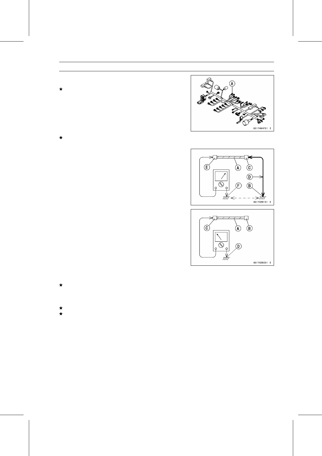
Pull each connector [A] apart and inspect it for corrosion,
dirt, and damage.
If the connector is corroded or dirty, clean it carefully. If it
is damaged, replace it. Connect the connectors securely.

Check the wiring for continuity.

Use the wiring diagram to find the ends of the lead which
is suspected of being a problem.

Connect the hand tester between the ends of the leads.

Special Tool - Hand Tester: 57001-1394

Set the tester to the × 1

range, and read the tester.

If the tester does not read 0

, the lead is defective. Re-

place the lead or the main harness.

If both ends of a harness [A] are far apart, ground [B] the
one end [C], using a jumper lead [D] and check the con-
tinuity between the end [E] and the ground [F]. This en-
ables to check a long harness for continuity. If the harness
is open, repair or replace the harness.

When checking a harness [A] for short circuit, open one
end [B] and check the continuity between the other end
[C] and ground [D]. If there is continuity, the harness has
a short circuit to ground, and it must be repaired or re-
placed.

Narrow down suspicious locations by repeating the con-
tinuity tests from the ECU connectors.
If no abnormality is found in the wiring or connectors, the
DFI parts are the next likely suspects. Check the part,
starting with input and output voltages. However, there is
no way to check the ECU itself.
If an abnormality is found, replace the affected DFI part.
If no abnormality is found in the wiring, connectors, and
DFI parts, replace the ECU.

3-30 FUEL SYSTEM (DFI)

Troubleshooting the DFI System

DFI Diagnosis Flow Chart

Inquiries to Rider

Each rider reacts to problems in different ways, so it is important to confirm what kind of symptoms
the rider has encountered.

Try to find out exactly what problem occurred under exactly what conditions by asking the rider;
knowing this information may help you reproduce the problem.

The following sample diagnosis sheet will help prevent you from overlooking any areas, and will
help you decide if it is a DFI system problem, or a general engine problem.

FUEL SYSTEM (DFI) 3-31

Troubleshooting the DFI System

Sample Diagnosis Sheet

Rider name:

Registration No. (license plate No.):

Year of initial registration:

Model:

Engine No.:

Frame No.:

Date problem occurred:

Mileage:

Environment when problem occurred.

Weather

fine,

cloudy,

rain,

snow,

always,

other:

Temperature

hot,

warm,

cold,

very cold,

always,

other:

Problem
frequency

chronic,

often,

once

Road

street,

highway,

mountain road (

uphill,

downhill),

bumpy,

pebble

Altitude

normal,

high (about 1 000 m or more)

Motorcycle conditions when problem occurred.

goes on immediately after turning the ignition switch on, and goes off after about
1 second (normal)

goes on immediately after turning the ignition switch on, goes off after about 1
second, and goes on again after about 4 seconds (ECU communication error)

goes on immediately after turning the ignition switch on, and stays on [DFI
problem]

Yellow engine
warning
indicator light
(LED)

does not go on after turning the ignition switch on [light (LED), meter unit fault]

Starts blinking about 1 seconds after ignition switch on, and the immobilizer
warning symbol on the LCD starts blinking (immobilizer system problem).

Does not go on about 1 seconds after ignition switch on (meter unit fault).

Red warning
indicator light
(LED)

light up (battery, oil pressure, water temperature, immobilizer or meter unit
problem)

starter motor not rotating.

starter motor rotating but engine do not turn over.

starter motor and engine do not turn over.

no fuel flow (

no fuel in tank,

no fuel pump sound).

no spark.

Starting
difficulty

other:

right after starting.

when opening throttle grip.

when closing throttle grip.

when moving off.

when stopping the motorcycle.

when cruising.

Engine stalls

other:

3-32 FUEL SYSTEM (DFI)

Troubleshooting the DFI System

very low idle speed,

very high idle speed,

rough idle speed.

battery voltage is low (charge the battery).

spark plug loose (tighten it).

spark plug dirty, broken, or gap maladjusted (remedy it).

backfiring.

afterfiring.

hesitation when acceleration.

engine oil viscosity too high.

brake dragging.

engine overheating.

clutch slipping.

Poor running
at low speed

other:

spark plug loose (tighten it).

spark plug dirty, broken, or gap maladjusted (remedy it).

spark plug incorrect (replace it).

knocking (fuel poor quality or incorrect,

use high-octane gasoline).

brake dragging.

clutch slipping.

engine overheating.

engine oil level too high.

engine oil viscosity too high.

Poor running
or no power at
high speed

other:

FUEL SYSTEM (DFI) 3-33

DFI System Troubleshooting Guide

NOTE

This is not an exhaustive list, giving every possible cause for each problem listed. It is meant
simply as a rough guide to assist the troubleshooting for some of the more common difficulties in
DFI system.

The ECU may be involved in the DFI electrical and ignition system troubles. If these parts and
circuits are checked out good, be sure to check the ECU for ground and power supply. If the
ground and power supply are checked good, replace the ECU.

Engine Won’t Turn Over

Symptoms or possible Causes

Actions

Gear position, starter lockout or sidestand switch
trouble

Inspect each switch (see chapter 16).

Immobilizer system trouble

Inspect (see chapter 17).

Vehicle-down sensor operated

Turn ignition switch off (see chapter 17).

Vehicle-down sensor trouble

Inspect (see chapter 17).

Crankshaft sensor trouble

Inspect (see chapter 16).

Stick coil shorted or not in good contact

Inspect or Reinstall (see chapter 16).

Stick coil trouble

Inspect (see chapter 16).

Spark plug dirty, broken or gap maladjusted

Inspect and replace (see chapter 16).

Spark plug incorrect

Replace it with the correct plug (see chapter 2).

ECU ground and power supply trouble

Inspect (see chapter 3).

ECU trouble

Inspect (see chapter 3).

No or little fuel in tank

Supply fuel (see Owner’s Manual).

Fuel injector trouble

Inspect and replace (see chapter 3).

Fuel pump not operating

Inspect (see chapter 3).

Fuel pump relay trouble

Inspect and replace (see chapter 3).

Fuel filter or pump screen clogged

Inspect and replace fuel pump (see chapter 3).

Fuel pressure regulator trouble

Inspect fuel pressure and replace fuel pump (see
chapter 3).

Fuel line clogged

Inspect and repair (see chapter 3).

Poor Running at Low Speed

Symptoms or Possible Causes

Actions

Spark weak:

Stick coil shorted or not in good contact

Inspect or reinstall (see chapter 16).

Stick coil trouble

Inspect (see chapter 16).

Spark plug dirty, broken or gap maladjusted

Inspect and replace (see chapter 16).

Spark plug incorrect

Replace it with the correct plug (see chapter 2).

ECU trouble

Inspect (see chapter 3).

Fuel/air mixture incorrect:

Little fuel in tank

Supply fuel (see Owner’s Manual).

Air cleaner clogged, poorly sealed, or missing

Clean element or inspect sealing (see chapter 2).

Air duct loose

Reinstall (see chapter 3).

Throttle body assy holder loose

Reinstall (see chapter 3).

Throttle body assy dust seal damage

Replace (see chapter 3).

Fuel injector O-ring damage

Replace (see chapter 3).

Fuel filter or pump screen clogged

Inspect and replace fuel pump (see chapter 3).

3-34 FUEL SYSTEM (DFI)

DFI System Troubleshooting Guide

Symptoms or Possible Causes

Actions

Fuel pressure regulator trouble

Inspect fuel pressure and replace fuel pump (see
chapter 3).

Fuel line clogged

Inspect and repair (see chapter 3).

Intake air pressure sensor #1 trouble

Inspect (see chapter 17).

Intake air pressure sensor #2 trouble

Inspect (see chapter 17).

Water temperature sensor trouble

Inspect (see chapter 17).

Intake air temperature sensor trouble

Inspect (see chapter 17).

Main throttle sensor trouble

Inspect (see chapter 17).

Subthrottle sensor trouble

Inspect (see chapter 17).

Subthrottle valve actuator trouble

Inspect (see chapter 17).

Unstable (rough) idling:

Fuel pressure too low or too high

Inspect (see chapter 3).

Fuel injector trouble

Inspect (see chapter 3).

Main throttle sensor trouble

Inspect (see chapter 17).

Subthrottle sensor trouble

Inspect (see chapter 17).

Subthrottle valve actuator trouble

Inspect (see chapter 17).

Engine vacuum not synchronizing

Inspect and adjust (see chapter 2).

Intake air pressure sensor #1 trouble

Inspect (see chapter 17).

Intake air pressure sensor #2 trouble

Inspect (see chapter 17).

Water temperature sensor trouble

Inspect (see chapter 17).

Intake air temperature sensor trouble

Inspect (see chapter 17).

Engine stalls easily:

Spark plug dirty, broken or gap maladjusted

Inspect and replace (see chapter 16).

Stick coil trouble

Inspect (see chapter 16).

Main throttle sensor trouble

Inspect (see chapter 17).

Subthrottle sensor trouble

Inspect (see chapter 17).

Subthrottle valve actuator trouble

Inspect (see chapter 17).

Intake air pressure sensor #1 trouble

Inspect (see chapter 17).

Intake air pressure sensor #2 trouble

Inspect (see chapter 17).

Water temperature sensor trouble

Inspect (see chapter 17).

Intake air temperature sensor trouble

Inspect (see chapter 17).

Fuel pump trouble

Inspect (see chapter 3).

Fuel injector trouble

Inspect (see chapter 3).

Fuel pressure too low or too high

Inspect (see chapter 3).

Fuel pressure regulator trouble

Inspect fuel pressure and replace fuel pump (see
chapter 3).

Fuel line clogged

Inspect and repair (see chapter 3).

Poor acceleration:

Fuel pressure too low

Inspect (see chapter 3).

Water or foreign matter in fuel

Change fuel. Inspect and clean fuel system (see
chapter 3).

Fuel filter or pump screen clogged

Inspect and replace fuel pump (see chapter 3).

Fuel pump trouble

Inspect (see chapter 3).

Fuel injector trouble

Inspect (see chapter 3).

Main throttle sensor trouble

Inspect (see chapter 17).

FUEL SYSTEM (DFI) 3-35

DFI System Troubleshooting Guide

Symptoms or Possible Causes

Actions

Subthrottle sensor trouble

Inspect (see chapter 17).

Subthrottle valve actuator trouble

Inspect (see chapter 17).

Intake air pressure sensor #1 trouble

Inspect (see chapter 17).

Intake air pressure sensor #2 trouble

Inspect (see chapter 17).

Water temperature sensor trouble

Inspect (see chapter 17).

Intake air temperature sensor trouble

Inspect (see chapter 17).

Spark plug dirty, broken or gap maladjusted

Inspect and replace (see chapter 16).

Stick coil trouble

Inspect (see chapter 16).

Stumble:

Fuel pressure too low

Inspect (see chapter 3).

Fuel injector trouble

Inspect (see chapter 3).

Main throttle sensor trouble

Inspect (see chapter 17).

Subthrottle sensor trouble

Inspect (see chapter 17).

Subthrottle valve actuator trouble

Inspect (see chapter 17).

Intake air pressure sensor #1 trouble

Inspect (see chapter 17).

Intake air pressure sensor #2 trouble

Inspect (see chapter 17).

Water temperature sensor trouble

Inspect (see chapter 17).

Intake air temperature sensor trouble

Inspect (see chapter 17).

Surge:

Unstable fuel pressure

Fuel pressure regulator trouble (Inspect and
replace fuel pump) or kinked fuel line (Inspect
and replace fuel pump) (see chapter 3).

Fuel injector trouble

Inspect (see chapter 3).

Water temperature sensor trouble

Inspect (see chapter 17).

Backfiring when deceleration:

Spark plug dirty, broken or gap maladjusted

Inspect and replace (see chapter 16).

Fuel pressure too low

Inspect (see chapter 3).

Fuel pump trouble

Inspect (see chapter 3).

Main throttle sensor trouble

Inspect (see chapter 17).

Subthrottle sensor trouble

Inspect (see chapter 17).

Subthrottle valve actuator trouble

Inspect (see chapter 17).

Intake air pressure sensor #1 trouble

Inspect (see chapter 17).

Intake air pressure sensor #2 trouble

Inspect (see chapter 17).

Water temperature sensor trouble

Inspect (see chapter 17).

Intake air temperature sensor trouble

Inspect (see chapter 17).

Air switching valve trouble

Inspect and replace (see chapter 16).

Air suction valve trouble

Inspect and replace (see chapter 5).

After fire:

Spark plug burned or gap maladjusted

Replace (see chapter 2).

Fuel injector trouble

Inspect (see chapter 3).

Intake air pressure sensor #1 trouble

Inspect (see chapter 17).

Intake air pressure sensor #2 trouble

Inspect (see chapter 17).

Water temperature sensor trouble

Inspect (see chapter 17).

Intake air temperature sensor trouble

Inspect (see chapter 17).

3-36 FUEL SYSTEM (DFI)

DFI System Troubleshooting Guide

Symptoms or Possible Causes

Actions

Other:

Intermittent any DFI fault and its recovery

Check that DFI connectors are clean and tight,
and examine leads for signs of burning or fraying
(see chapter 3).

Poor Running or No Power at High Speed

Symptoms or Possible Causes

Actions

Firing incorrect:

Stick coil shorted or not in good contact

Inspect or Reinstall (see chapter 16).

Stick coil trouble

Inspect (see chapter 16).

Spark plug dirty, broken or gap maladjusted

Inspect and replace (see chapter 16).

Spark plug incorrect

Replace it with the correct plug (see chapter 2).

ECU trouble

Inspect (see chapter 3).

Fuel/air mixture incorrect:

Air cleaner clogged, poorly sealed, or missing

Clean element or inspect sealing (see chapter 2).

Air duct loose

Reinstall (see chapter 3).

Throttle body assy holder loose

Reinstall (see chapter 3).

Throttle body assy dust seal damage

Replace (see chapter 3).

Water or foreign matter in fuel

Change fuel. Inspect and clean fuel system (see
chapter 3).

Fuel injector O-ring damage

Replace (see chapter 3).

Fuel injector clogged

Inspect and repair (see chapter 3).

Fuel line clogged

Inspect and repair (see chapter 3).

Fuel pump operates intermittently and often DFI
fuse blows.

Fuel pump bearings may wear. Replace the fuel
pump (see chapter 3).

Fuel pump trouble

Inspect (see chapter 3).

Intake air pressure sensor #1 trouble

Inspect (see chapter 17).

Intake air pressure sensor #2 trouble

Inspect (see chapter 17).

Cracked or obstructed intake air pressure sensor
#1 and #2 vacuum hoses

Inspect and repair or replace (see chapter 3).

Water temperature sensor trouble

Inspect (see chapter 17).

Intake air temperature sensor trouble

Inspect (see chapter 17).

Main throttle sensor trouble

Inspect (see chapter 17).

Subthrottle sensor trouble

Inspect (see chapter 17).

Subthrottle valve actuator trouble

Inspect (see chapter 17).

Knocking:

Fuel poor quality or incorrect

Fuel change (Use the gasoline recommended in
the Owner’s Manual).

Spark plug incorrect

Replace it with the correct plug (see chapter 2).

Stick coil trouble

Inspect (see chapter 16).

ECU trouble

Inspect (see chapter 3).

Engine vacuum not synchronizing

Inspect and adjust (see chapter 2).

Intake air pressure sensor #1 trouble

Inspect (see chapter 17).

Intake air pressure sensor #2 trouble

Inspect (see chapter 17).

Water temperature sensor trouble

Inspect (see chapter 17).

Intake air temperature sensor trouble

Inspect (see chapter 17).

FUEL SYSTEM (DFI) 3-37

DFI System Troubleshooting Guide

Symptoms or Possible Causes

Actions

Miscellaneous:

Subthrottle sensor trouble

Inspect (see chapter 17).

Subthrottle valve actuator trouble

Inspect (see chapter 17).

Throttle valves will not fully open

Inspect throttle cables and lever linkage (see
chapter 3).

Engine overheating - Water temperature sensor
or crankshaft sensor trouble

(see Overheating of Troubleshooting Guide in
chapter 18)

Air switching valve trouble

Inspect and replace (see chapter 16).

Air suction valve trouble

Inspect and replace (see chapter 5).

Exhaust Smokes Excessively:

(Black smoke)

Air cleaner element clogged

Clean element (see chapter 2).

Fuel pressure too high

Inspect (see chapter 3).

Fuel injector trouble

Inspect (see chapter 3).

Water temperature sensor trouble

Inspect (see chapter 17).

Intake air temperature sensor trouble

Inspect (see chapter 17).

(Brown smoke)

Air duct loose

Reinstall (see chapter 3).

Fuel pressure too low

Inspect (see chapter 3).

Water temperature sensor trouble

Inspect (see chapter 17).

Intake air temperature sensor trouble

Inspect (see chapter 17).

3-38 FUEL SYSTEM (DFI)

Warning Indicator Light (LED)

Yellow Engine Warning/Red Warning Indicator
Light (LED) Inspection

Yellow Engine Warning Indicator Light (LED) [A]
Red Warning Indicator Light (LED) [B]

In this model, the above mentioned warning indicator
lights (LED) go on or blink by the data sent from the ECU.

Refer to the Meter Operation Inspection in the Electrical
System chapter.

Warning Indicator Light (LED) Circuit

1. ECU
2. Meter Unit
3. Red Warning Indicator Light (LED)
4. Yellow Engine Warning Indicator Light (LED)

FUEL SYSTEM (DFI) 3-39

ECU

ECU Identification

Most countries have their own regulations, so each ECU
has different characteristic. So, do not confuse ECU with
each other and use only the ECU for your model. Other-
wise, the motorcycle cannot clear the regulation.

ECU Identification

Part Number [A]

Specification

US, without Immobilizer

21175-0810

CA, without Immobilizer

AU, with Immobilizer

ID, with Immobilizer

WVTA (FULL H), with Immobilizer

21175-0811

GB WVTA (FULL H), with Immobilizer

21175-0812

CAL, without Immobilizer

21175-0813

SEA, with Immobilizer

21175-0814

WVTA (78.2 H), with Immobilizer

21175-0835

BR, with Immobilizer

ECU Removal

NOTICE

Never drop the ECU especially on a hard surface.
Such a shock to the ECU can damage it.

Remove the front seat cover (see Seat Cover Removal in
the Frame chapter).

Remove the turn signal relay [A] from the rear fender.

Remove the relay box [B] from the rubber protector.

Open the clamp [A].

Disconnect the ECU connectors [B].

Remove:

ECU [A] (with Rubber Protector [B])

Lift up the ECU with rubber protector to clear the projec-
tions [C].

3-40 FUEL SYSTEM (DFI)

ECU

For GB WVTA (FULL H) and WVTA (78.2 H) models, note
the following.

Using a small chisel or other suitable tool, remove the
screws [A].

Remove:

Upper Guard [B]
Lower Guard [C]

ECU Installation

Install:

ECU [A] (in Rubber Protector [B])

Insert the slits of the rubber protector to the projections
[C] of the rear fender.

For GB WVTA (FULL H) and WVTA (78.2 H) models, note
the following.

Install:

Lower Guard [A]
Upper Guard [B]

Tighten the new screws [C] using the Kawasaki genuine
screws of which threads are coated with locking agent.

Connect the ECU connectors [A].

Hold the main harness to the clamp [B].

Install:

Relay Box [A]
Turn Signal Relay [B]
Front Seat Cover (see Seat Cover Installation in the
Frame chapter)

FUEL SYSTEM (DFI) 3-41

ECU

ECU Power Supply Inspection

Remove the front seat cover (see Seat Cover Removal in
the Frame chapter).

Visually inspect the ECU connectors.
If the connector is clogged with mud or dust, blow it off
with compressed air.

Remove the ECU (see ECU Removal).

Visually inspect the terminals [A] of the ECU and main
harness connectors.
If the terminals of the main harness connectors are dam-
aged, replace the main harness.
If the terminals of the ECU connectors are damaged, re-
place the ECU.

Turn the ignition switch off.

Disconnect the ECU connectors.

Gray Connector [A]

Set the hand tester [B] to the × 1

range and check the

following wiring for continuity.

Special Tool - Hand Tester: 57001-1394

ECU Grounding Inspection

Connections:

(I) BK/Y leads (ECU

terminal 39 or 65)
BK/BL leads (ECU
terminal 38)

←→

Battery (–) Terminal

(II) Engine Ground

←→

Battery (–) Terminal

Criteria:

Both: 0

If no continuity, check the connectors, the engine ground
lead, or main harness, and repair or replace them if nec-
essary.

3-42 FUEL SYSTEM (DFI)

ECU

If the wiring is good, check the power source voltage of
the ECU.

NOTE

Be sure the battery is fully charged.

Connect the ECU connectors.

Connect a digital meter [A] to the connector (black) [B]
with the needle adapter set.

Special Tool - Needle Adapter Set: 57001-1457

ECU Power Supply Inspection

Connections:

(I) Digital Meter (+)

Terminal 6 (BR/W)

Digital Meter (–)

Battery (–) terminal

(II) Digital Meter (+)

Terminal 7 (W/BK)

Digital Meter (–)

Battery (–) terminal

Ignition Switch OFF:

Terminal 6 (BR/W): 0 V

Terminal 7 (W/BK): Battery Voltage

Ignition Switch ON:

All: Battery Voltage

If the reading is out of the specification, check the follow-
ing.

Main Fuse 30 A (see Fuse Inspection in the Electrical
System chapter)
ECU Fuse 15 A (see Fuse Inspection in the Electrical
System chapter)
ECU Main Relay (see Relay Circuit Inspection in the
Electrical System chapter)
Power Source Wiring (see wiring diagram in this section)

FUEL SYSTEM (DFI) 3-43

ECU

ECU Power Source Circuit

1. ECU
2. Joint Connector C
3. Frame Ground 2
4. Frame Ground 3
5. Frame Ground 1
6. Engine Ground
7. Battery 12 V 8 Ah
8. Starter Relay
9. Main Fuse 30 A

10. ECU Fuse 15 A

11. Relay Box

12. ECU Main Relay
13. Fuse Box 1
14. Ignition Fuse 15 A
15. Joint Connector E
16. Ignition Switch
17. Joint Connector D

3-44 FUEL SYSTEM (DFI)

CAN Communication Line

CAN Communication Line Resistance Inspection

In this model, resistors for CAN communication line are
built in the ECU [A] and meter unit.

Refer to the Meter Unit Inspection in the Electrical System
chapter for the resistor in the meter unit.

Turn the ignition switch off.

Remove:

ECU (see ECU Removal)

Connect a digital meter [A] to the ECU connector (gray)
[B].

Measure the resistance of the CAN communication line
resistor.

Special Tool - Hand Tester: 57001-1394

CAN Communication Line Resistance (at ECU
Connector)

Connections: Terminal 36

←→

Terminal 37

Standard: 118

122

If the reading is out of the range, replace the ECU (see
ECU Removal/Installation).
If the reading is within the range, resistor of the ECU for
CAN communication line is normal.

Check the wiring for continuity of the CAN communication
line (see wiring diagram in this section).

Special Tool - Hand Tester: 57001-1394

If the wiring is open, repair or replace the main harness.

FUEL SYSTEM (DFI) 3-45

CAN Communication Line

CAN Communication Line Circuit

1. ECU
2. KIBS Hydraulic Unit (Equipped Models)
3. Meter Unit

3-46 FUEL SYSTEM (DFI)

DFI Power Source

ECU Fuse Removal

Refer to the 30 A Main/15 A ECU Fuse Removal in the
Electrical System chapter.

ECU Fuse Installation

If a fuse fails during operation, inspect the DFI system to
determine the cause, and then replace it with a new fuse
of proper amperage.

Refer to the Fuse Installation in the Electrical System
chapter.

ECU Fuse Inspection

Refer to the Fuse Inspection in the Electrical System
chapter.

ECU Main Relay Removal/Installation

The ECU main relay is built in the relay box [A].

Refer to the Relay Box Removal in the Electrical System
chapter.

ECU Main Relay Inspection

Refer to the Relay Circuit Inspection in the Electrical Sys-
tem chapter.

FUEL SYSTEM (DFI) 3-47

Fuel Line

Fuel Pressure Inspection

NOTE

Be sure the battery is fully charged.

Remove:

Fuel Tank Bolts [A]
Fuel Hose (see Fuel Hose Replacement in the Periodic
Maintenance chapter)

Be sure to place a piece of cloth around the fuel outlet
pipe of the fuel pump and the delivery pipe of the throttle
body assy.

WARNING

Fuel is flammable and explosive under certain con-
ditions and can cause severe burns. Be prepared
for fuel spillage; any spilled fuel must be completely
wiped up immediately. When the fuel hose is dis-
connected, fuel spills out from the hose and the
pipe because of residual pressure. Cover the hose
connection with a piece of clean cloth to prevent
fuel spillage.

Install the fuel pressure gauge adapter [A] and fuel hoses
(Special Tool: 57001-1607) [B] between the fuel outlet
pipe and delivery pipe.

Secure the fuel hoses with the clamps.

Connect the pressure gauge [C] to the fuel pressure
gauge adapter.

Special Tools - Oil Pressure Gauge, 5 kgf/cm²: 57001-125

Fuel Pressure Gauge Adapter: 57001-1593
Fuel Hose: 57001-1607

WARNING

Fuel is extremely flammable and can be explosive
under certain conditions resulting in serious injury
or death. Do not try to start the engine with the fuel
hoses disconnected.

Turn the engine stop switch run position.

Turn the ignition switch on.

The fuel pump should operate for 3 seconds, and then
should stop.

NOTE

After turning on the engine stop switch and ignition
switch, inspect the fuel leakage from the connected
portion of the special tools.

NOTICE

Do not drive the fuel pump for 3 seconds or more
without the fuel in the fuel tank. If the fuel pump is
driven without the fuel, it may be damaged.

Start the engine, and let it idle.

Measure the fuel pressure with the engine idling.

Fuel Pressure (with Engine Idling)

Standard:

294 kPa (3.0 kgf/cm², 43 psi)

3-48 FUEL SYSTEM (DFI)

Fuel Line

NOTE

The gauge needle will fluctuate. Read the pressure at
the average of the maximum and minimum indications.

Turn the ignition switch off.
If the fuel pressure is much higher than specified, replace
the fuel pump because the fuel pressure regulator in the
fuel pump have been clogged or stuck.
If the fuel pressure is much lower than specified, check
the following.

Fuel Line Leakage (see Fuel Injector Fuel Line Inspec-
tion)
Amount of Fuel Flow (see Fuel Flow Rate Inspection)

After above checks, measure the fuel pressure again.

Remove the fuel pressure gauge, hoses and adapter.

Install:

Fuel Hose (see Fuel Hose Replacement in the Periodic
Maintenance chapter)
Fuel Tank (see Fuel Tank Installation)

Start the engine and check for fuel leakage.

Fuel Flow Rate Inspection

WARNING

Gasoline is extremely flammable and can be explo-
sive under certain conditions, creating the potential
for serious burns. Make sure the area is well venti-
lated and free from any source of flame or sparks;
this includes any appliance with a pilot light. Do not
smoke. Turn the ignition switch off. Be prepared for
fuel spillage; any spilled fuel must be completely
wiped up immediately.

NOTE

Be sure the battery is fully charged.

Turn the ignition switch off.

Wait until the engine cools down.

Prepare a fuel hose (Special Tool: 57001-1607) and a
measuring cylinder.

Special Tool - Fuel Hose: 57001-1607

Remove the fuel tank bolts [A].

FUEL SYSTEM (DFI) 3-49

Fuel Line

Open the fuel tank cap [A] to lower the pressure in the
tank.

Remove the fuel hose from the fuel pump (see Fuel Tank
Removal).

Be sure to place a piece of cloth around the fuel outlet
pipe of the fuel pump.

WARNING

Fuel is flammable and explosive under certain con-
ditions and can cause severe burns. Be prepared
for fuel spillage; any spilled fuel must be completely
wiped up immediately. When the fuel hose is dis-
connected, fuel spills out from the hose and the
pipe because of residual pressure. Cover the hose
connection with a piece of clean cloth to prevent
fuel spillage.

Connect the prepared fuel hose [A] to the fuel outlet pipe.

Secure the fuel hose with a clamp.

Insert the fuel hose into the measuring cylinder [B].

WARNING

Wipe off spilled out fuel immediately.
Be sure to hold the measuring cylinder vertical.

Close the fuel tank cap.

Turn the engine stop switch to run position.

Turn the ignition switch on.

The fuel pump should operate for 3 seconds, and then
should stop.

NOTICE

Do not drive the fuel pump for 3 seconds or more
without the fuel in the fuel tank. If the fuel pump is
driven without the fuel, it may be damaged.

Measure the discharge for 3 seconds.

Repeat this operation several times.

Amount of Fuel Flow

Standard:

50 mL (1.7 US oz.) or more for 3 seconds

Turn the ignition switch off.
If the fuel flow is much less than the specified, replace the
fuel pump (see Fuel Pump Removal/Installation).

Install the fuel tank (see Fuel Tank Installation).

Start the engine and check for fuel leakage.

3-50 FUEL SYSTEM (DFI)

Fuel Pump

Fuel Pump Removal

WARNING

Gasoline is extremely flammable and can be explo-
sive under certain conditions, creating the potential
for serious burns. Make sure the area is well venti-
lated and free from any source of flame or sparks;
this includes any appliance with a pilot light. Do not
smoke. Turn the ignition switch off. Disconnect the
battery (–) terminal. To avoid fuel spills, draw it from
the tank when the engine is cold. Be prepared for
fuel spillage; any spilled fuel must be completely
wiped up immediately.

NOTICE

Never drop the fuel pump especially on a hard sur-
face. Such a shock to the pump can damage it.

Draw the fuel out from the fuel tank with a commercially
available electric pump.

Remove the fuel tank (see Fuel Tank Removal).

Be careful of fuel spillage from the fuel tank since fuel still
remains in the fuel tank and fuel pump. Plug the fuel pipe
of the fuel tank.

Turn the fuel tank upside down.

Unscrew the fuel pump bolts [A], and take out the fuel
pump [B].

NOTICE

Do not pull the leads of the fuel pump. If they are
pulled, the lead terminals may be damaged.

Discard the fuel pump gasket [A].

FUEL SYSTEM (DFI) 3-51

Fuel Pump

Fuel Pump Installation

Remove dirt or dust from the fuel pump [A] by lightly ap-
plying compressed air.

Replace the fuel pump gasket with a new one.

Check that the fuel pump terminal [A] and band [B] are in
place.

Apply a non-permanent locking agent to the threads of
the fuel pump bolts.

Tighten the fuel pump bolts [C] to a snug fit.

Tighten the fuel pump bolts alternating diagonally.

Torque - Fuel Pump Bolts: 9.8 N·m (1.0 kgf·m, 87 in·lb)

Tighten the fuel pump bolts again to check the tightness.

Fuel Pump Operation Inspection

NOTE

Be sure the battery is fully charged.

Turn the engine stop switch to run position.

Turn the ignition switch on and make sure that the fuel
pump operates (make light sounds) for 3 seconds, and
then stops.

Turn the ignition switch off.
If the pump does not operate as described above, check
the operating voltage (see Fuel Pump Operating Voltage
Inspection).

3-52 FUEL SYSTEM (DFI)

Fuel Pump

Fuel Pump Operating Voltage Inspection

NOTE

Be sure the battery is fully charged.

Turn the ignition switch off.

Remove the front seat (see Front Seat Removal in the
Frame chapter).

Disconnect the fuel pump lead connector and connect
the measuring adapter [A] between these connectors as
shown.

Main Harness [B]
Fuel Pump [C]

Special Tool - Measuring Adapter: 57001-1700

Connect a digital meter [D] to the measuring adapter
leads.

Fuel Pump Operating Voltage

Connections to Adapter:

Digital Meter (+)

R (pump BK/Y) lead

Digital Meter (–)

BK (pump BK/W) lead

Measure the operating voltage with engine stopped and
with the connector joined.

Turn the engine stop switch run position.

Turn the ignition switch on.

Operating Voltage

Standard: Battery Voltage for 3 seconds, and then 0 V

Turn the ignition switch off.
If the reading stays on battery voltage and never shows 0
V, check the fuel pump relay (see Relay Circuit Inspection
in the Electrical System chapter).
If the fuel pump relay is normal, check the ECU for its
ground and power supply (see ECU Power Supply In-
spection).
If the ground and power supply are good, replace the ECU
(see ECU Removal/Installation).
If there is still no battery voltage, check the fuel pump re-
lay (see Relay Circuit Inspection in the Electrical System
chapter).
If the fuel pump relay is normal, check the wiring for con-
tinuity (see wiring diagram in this section).

Special Tool - Hand Tester: 57001-1394

If the wiring is good, check the ECU for its ground and
power supply (see ECU Power Supply Inspection).
If the ground and power supply are good, replace the ECU
(see ECU Removal/Installation).
If the reading is in specification, but the pump does not op-
erate, replace the fuel pump (see Fuel Pump Removal/In-
stallation).

FUEL SYSTEM (DFI) 3-53

Fuel Pump

Pressure Regulator Removal

The pressure regulator [A] is built into the fuel pump and
can not be removed.

Fuel Filter Cleaning

The fuel filter [A] is built into the fuel pump and can not be
cleaned or checked.
If the fuel filter is suspected of clogging or being damaged,
replace it with the fuel pump as a set.

3-54 FUEL SYSTEM (DFI)

Fuel Pump

Fuel Pump Circuit

1. ECU
2. Joint Connector C
3. Frame Ground 2
4. Engine Ground
5. Battery 12 V 8 Ah
6. Stater Relay
7. Main Fuse 30 A
8. ECU Fuse 15 A
9. Fuel Pump

10. Relay Box

11. Fuel Pump Relay

12. Fuse Box 1
13. Ignition Fuse 15 A
14. Joint Connector E
15. Ignition Switch
16. Engine Stop Switch

FUEL SYSTEM (DFI) 3-55

Fuel Injectors

Fuel Injector Removal/Installation

Refer to the Throttle Body Assy Disassembly/Assembly.

Fuel Injector Audible Inspection

NOTE

Be sure the battery is fully charged.

Remove:

Fuel Tank (see Fuel Tank Removal)
Fuel Hose (see Fuel Hose Replacement in the Periodic
Maintenance chapter)

Connect the following parts temporarily.

Fuel Pump Lead Connector [A]
Extension Tube [B]

Special Tool - Extension Tube: 57001-1578

Start the engine, and let it idle.

Apply the standard tip screwdriver [A] to the fuel injector
[B]. Put the grip end onto your ear, and listen whether the
fuel injector is clicking or not.

A sound scope can also be used.

The click interval becomes shorter as the engine speed
rises.

Do the same for the other fuel injectors.
If all the fuel injectors click at a regular intervals, the fuel
injectors are normal.

Turn the ignition switch off.
If any fuel injector does not click, check the fuel injector
resistance (see Fuel Injector Resistance Inspection).

Fuel Injector Resistance Inspection

Remove:

Fuel Tank (see Fuel Tank Removal)

Disconnect:

Air Cleaner Dain Hose [A]
Breather Hose [B]
Fuel Injector Connector [C]

Connect a digital meter to the terminals in each fuel injec-
tor [A].

Measure the fuel injector resistance.

Fuel Injector Resistance

Standard:

About 11.7

12.3

at 20°C (68°F)

If the reading is out of the standard, replace the fuel in-
jector.
If the reading is within the standard, check the power
source voltage (see Fuel Injector Power Source Voltage
Inspection).

3-56 FUEL SYSTEM (DFI)

Fuel Injectors

Fuel Injector Power Source Voltage Inspection

NOTE

Be sure the battery is fully charged.

Turn the ignition switch off.

Remove the air cleaner drain hose and breather hose
(see Air Cleaner Housing Removal).

Disconnect the injector connector and connect the mea-
suring adapter [A] between these connectors as shown.

Main Harness [B]
Fuel Injector #1 [C]

Special Tool - Measuring Adapter: 57001-1700

Connect a digital meter [D] to the measuring adapter lead.

Fuel Injector Power Source Voltage

Connections to Adapter:

For Fuel Injector #1, #2, #3, #4

Digital Meter (+)

R (injector W/R) lead

Digital Meter (–)

Battery (–) terminal

Measure the power source voltage with the engine
stopped.

Turn the engine stop switch to run position.

Turn the ignition switch on.

Power Source Voltage

Standard:

Battery Voltage for 3 seconds, and then 0 V

Turn the ignition switch off.
If the reading stays on battery voltage and never shows 0
V, check the fuel pump relay (see Relay Circuit Inspection
in the Electrical System chapter).
If the fuel pump relay is normal, check the ECU for its
ground and power supply (see ECU Power Supply In-
spection).
If the ground and power supply are good, replace the ECU
(see ECU Removal/Installation).
If there is still no battery voltage, check the fuel pump re-
lay (see Relay Circuit Inspection in the Electrical System
chapter).
If the fuel pump relay is normal, check the power source
wiring (see wiring diagram in this section).

Special Tool - Hand Tester: 57001-1394

If the wiring is good, check the ECU for its ground and
power supply (see ECU Power Supply Inspection).
If the ground and power supply are good, replace the ECU
(see ECU Removal/Installation).
If the reading is in specification, check the output voltage
(see Fuel Injector Output Voltage Inspection).

FUEL SYSTEM (DFI) 3-57

Fuel Injectors

Fuel Injector Output Voltage Inspection

NOTE

Be sure the battery is fully charged.

Turn the ignition switch off.

Remove the ECU (see ECU Removal).

Do not disconnect the ECU connector.

Connect a digital meter [A] to the connector [B] with the
needle adapter set.

Special Tool - Needle Adapter Set: 57001-1457

Fuel Injector Output Voltage

Connections to ECU Connector:

For Fuel Injector #1

Digital Meter (+)

BL/BK lead (ECU terminal 42)

Digital Meter (–)

Battery (–) terminal

For Fuel Injector #2

Digital Meter (+)

BL/R lead (ECU terminal 41)

Digital Meter (–)

Battery (–) terminal

For Fuel Injector #3

Digital Meter (+)

BL/O lead (ECU terminal 40)

Digital Meter (–)

Battery (–) terminal

For Fuel Injector #4

Digital Meter (+)

BL/G lead (ECU terminal 54)

Digital Meter (–)

Battery (–) terminal

Measure the output voltage with the engine stopped and
with the connector joined.

Turn the engine stop switch to run position.

Turn the ignition switch on.

Output Voltage

Standard:

Battery Voltage for 3 seconds, and then 0 V

Turn the ignition switch off.
If the reading is in specification, check the ECU for its
ground and power supply (see ECU Power Supply In-
spection).
If the ground and power supply are good, replace the ECU
(see ECU Removal/Installation).

3-58 FUEL SYSTEM (DFI)

Fuel Injectors

If the reading is out of the specification, remove the ECU
and check the wiring for continuity between main harness
connectors.

Special Tool - Hand Tester: 57001-1394

Disconnect the ECU and injector connector.

Wiring Continuity Inspection

ECU Connector (Gray)
[A]

←→

Fuel Injector Connector
[B]

For Fuel Injector #1 [C]

BL/BK lead (ECU terminal 42) [D]

For Fuel Injector #2

BL/R lead (ECU terminal 41)

For Fuel Injector #3

BL/O lead (ECU terminal 40)

For Fuel Injector #4

BL/G lead (ECU terminal 54)

If the wiring is good, check the ECU for its ground and
power supply (see ECU Power Supply Inspection).
If the ground and power supply are good, replace the ECU
(see ECU Removal/Installation).

Fuel Injector Fuel Line Inspection

Remove:

Fuel Tank (see Fuel Tank Removal)
Fuel Hose (see Fuel Hose Replacement in the Periodic
Maintenance chapter)

Be sure to place a piece of cloth around the fuel outlet
pipe of the fuel pump and the delivery pipe of the throttle
body assy.

WARNING

Fuel is flammable and explosive under certain con-
ditions and can cause severe burns. Be prepared
for fuel spillage; any spilled fuel must be completely
wiped up immediately. When the fuel hose is dis-
connected, fuel spills out from the hose and the
pipe because of residual pressure. Cover the hose
connection with a piece of clean cloth to prevent
fuel spillage.

Check the fuel injector line for leakage as follows.

Connect a commercially available vacuum/pressure
pump [A] to the nipple of the delivery pipe [B] with the
fuel hose [C] (both ends with the clamps [D]) as shown.

Apply soap and water solution to the areas [E] as shown.

Watching the pressure gauge, squeeze the pump lever,
and build up the pressure until the pressure reaches the
maximum pressure.

Injector Fuel Line Maximum Pressure

Standard:

300 kPa (3.06 kgf/cm², 43 psi)

NOTICE

During pressure testing, do not exceed the maxi-
mum pressure for which the system is designed.

FUEL SYSTEM (DFI) 3-59

Fuel Injectors

Watch the gauge for at least 6 seconds.
If the pressure holds steady, the fuel line is good.
If the pressure drops at once or if bubbles are found in the
area, the fuel line is leaking. Replace the delivery pipe
assy, injectors and related parts.

Repeat the leak test, and check the fuel line for no leak-
age.

Install:

Fuel Hose (see Fuel Hose Replacement in the Periodic
Maintenance chapter)
Fuel Tank (see Fuel Tank Removal)

Start the engine and check for fuel leakage.

3-60 FUEL SYSTEM (DFI)

Fuel Injectors

Fuel Injector Circuit

1. ECU
2. Joint Connector C
3. Frame Ground 2
4. Engine Ground
5. Battery 12 V 8 Ah
6. Starter Relay
7. Main Fuse 30 A
8. ECU Fuse 15 A
9. Relay Box

10. Fuel Pump Relay

11. Fuse Box 1

12. Ignition Fuse 15 A
13. Joint Connector E
14. Ignition Switch
15. Engine Stop Switch
16. Fuel Injector #1
17. Fuel Injector #2
18. Fuel Injector #3
19. Fuel Injector #4


Content      ..     3      4      5      6     ..