Kawasaki Motorcycle Ninja ZX-6R / Ninja ZX-6R ABS. Service Manual (2013 year) - page 3
 

  Index      Manuals     Kawasaki Motorcycle Ninja ZX-6R / Ninja ZX-6R ABS. Service Manual (2013 year)


Search            copyright infringement  


Content      ..     1      2      3      4      ..


Kawasaki Motorcycle Ninja ZX-6R / Ninja ZX-6R ABS. Service Manual (2013 year) - page 3


PERIODIC MAINTENANCE 2-29

Periodic Maintenance Procedures

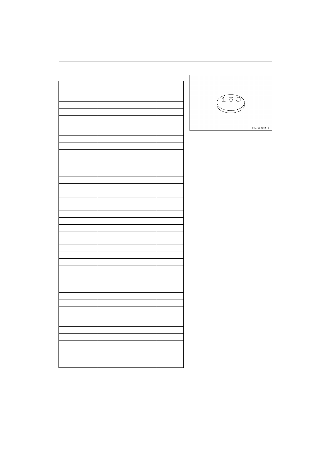
Adjustment Shims

Thickness

Part Number

Mark

1.300

92180-0108

130

1.325

92180-0109

132

1.350

92180-0110

135

1.375

92180-0111

138

1.400

92180-0112

140

1.425

92180-0113

142

1.450

92180-0114

145

1.475

92180-0115

148

1.500

92180-0116

150

1.525

92180-0117

152

1.550

92180-0118

155

1.575

92180-0119

158

1.600

92180-0120

160

1.625

92180-0121

162

1.650

92180-0122

165

1.675

92180-0123

168

1.700

92180-0124

170

1.725

92180-0125

172

1.750

92180-0126

175

1.775

92180-0127

178

1.800

92180-0128

180

1.825

92180-0129

182

1.850

92180-0130

185

1.875

92180-0131

188

1.900

92180-0132

190

1.925

92180-0133

192

1.950

92180-0134

195

1.975

92180-0135

198

2.000

92180-0136

200

2.025

92180-0137

202

2.050

92180-0138

205

2.075

92180-0139

208

2.100

92180-0140

210

2.125

92180-0141

212

2.150

92180-0142

215

2.175

92180-0143

218

2.200

92180-0144

220

2.225

92180-0145

222

2.250

92180-0146

225

2.275

92180-0147

228

2.300

92180-0148

230

2-30 PERIODIC MAINTENANCE

Periodic Maintenance Procedures

NOTICE

Be sure to remeasure the clearance after selecting
a shim. The clearance can be out of the specified
range because of the shim tolerance.

If there is no valve clearance, use a shim that is a few
sizes smaller, and remeasure the valve clearance.

When installing the shim, face the marked side toward the
valve lifter. At this time, apply engine oil to the shim or
the valve lifter to keep the shim in place during camshaft
installation.

NOTICE

Do not put shim stock under the shim. This may
cause the shim to pop out at high rpm, causing ex-
tensive engine damage.
Do not grind the shim. This may cause it to fracture,
causing extensive engine damage.

Apply molybdenum disulfide oil solution to the valve lifter
surface and install the lifter.

Install the camshafts (see Camshaft Installation in the En-
gine Top End chapter).

Recheck the valve clearance and readjust if necessary.

Install the removed parts (see appropriate chapters).

Air Suction System Damage Inspection

Disconnect the air switching valve hose [A] from the lower
air cleaner housing [B] (see Air Cleaner Housing Removal
in the Fuel System (DFI) chapter).

Connect the following parts temporarily.

Fuel Pump Lead Connector [A]
Extension Tube [B]
Air Cleaner Housing (see Air Cleaner Housing Installa-
tion in the Fuel System (DFI) chapter)

Special Tool - Extension Tube: 57001-1578

PERIODIC MAINTENANCE 2-31

Periodic Maintenance Procedures

Start the engine and run it at idle speed.

Plug the air switching valve hose end [A] with your finger
and feel vacuum pulsing in the hose.
If there is no vacuum pulsation, check the hose line for
leak. If there is no leak, check the air switching valve
(see Air Switching Valve Unit Test in the Electrical Sys-
tem chapter) or air suction valve (see Air Suction Valve
Inspection in the Engine Top End chapter).

Clutch

Clutch Operation Inspection

Pull the clutch lever just enough to take up the free play
[A].

Measure the gap between the lever and the lever holder.
If the gap is too wide, the clutch may not release fully. If
the gap is too narrow, the clutch may not engage fully. In
either case, adjust it.

Clutch Lever Free Play

Standard:

2

3 mm (0.08

0.12 in.)

WARNING

The engine and exhaust system get extremely hot
during normal operation and can cause serious
burns.

Never touch the engine or exhaust pipe

during clutch adjustment.

Turn the adjuster [A] so that 4

6 mm (0.16

0.24 in.) [B]

of threads is visible.

Slide the dust cover [A] at the clutch cable lower end out
of place.

Loosen both adjusting nuts [B] at the bracket [C] on the
clutch cover as far as they will go.

Pull the clutch outer cable [D] tight and tighten the adjust-
ing nuts against the bracket.

Slip the dust cover back onto place.

Turn the adjuster at the clutch lever until the free play is
correct.

2-32 PERIODIC MAINTENANCE

Periodic Maintenance Procedures

Push the release lever [A] toward the front of the motor-
cycle until it becomes hard to turn.

At this time, the release lever should have the proper an-
gle shown.

60° [B]

If the angle is wrong, check the clutch and release parts
for wear.

WARNING

Too much cable play can prevent clutch disengage-
ment and cause an accident resulting in serious in-
jury or death. When adjusting the clutch or replac-
ing the cable, be sure the upper end of the clutch
outer cable is fully seated in its fitting, or it could
slip into place later, creating enough cable play to
prevent clutch disengagement.

After the adjustment, start the engine and check that the
clutch does not slip and that it releases properly.

Engine Lubrication System

Engine Oil Change

Situate the motorcycle so that it is vertical after warming
up the engine.

Remove the engine oil drain bolt [A] to drain the oil.

The oil in the oil filter can be drained by removing the filter
(see Oil Filter Replacement).

Replace the drain bolt gasket [B] with a new one.

Tighten the drain bolt.

Torque - Engine Oil Drain Bolt: 29 N·m (3.0 kgf·m, 21 ft·lb)

Remove the oil filler plug [A].

PERIODIC MAINTENANCE 2-33

Periodic Maintenance Procedures

Pour in the specified type and amount of oil.

Recommended Engine Oil

Type:

API SG, SH, SJ, SL or SM with JASO MA,
MA1 or MA2

Viscosity:

SAE 10W-40

Capacity:

2.8 L (3.0 US qt) (when filter is not removed)

3.1 L (3.3 US qt) (when filter is removed)

3.6 L (3.8 US qt) (when engine is completely
dry)

NOTE

Do not add any chemical additive to the oil.Oils fulfilling
the above requirements are fully formulated and provide
adequate lubrication for both the engine and the clutch.

Although 10W-40 engine oil is the recommended oil
for most conditions, the oil viscosity may need to be
changed to accommodate atmospheric conditions in
your riding area.

Replace the O-ring of the oil filler plug with a new one.

Apply engine oil to the new O-ring.

Install the oil filler plug.

Torque - Oil Filler Plug: Hand-tighten

Check the oil level (see Oil Level Inspection in the Engine
Lubrication System chapter).

Oil Filter Replacement

Drain the engine oil (see Engine Oil Change).

Remove the oil filter [A] with the oil filter wrench [B].

Special Tool - Oil Filter Wrench: 57001-1249

Replace the filter with a new one.

Apply grease to the gasket [A] before installation.

Tighten the filter with the oil filter wrench.

Special Tool - Oil Filter Wrench: 57001-1249

Torque - Oil Filter: 17 N·m (1.7 kgf·m, 13 ft·lb)

NOTE

Hand tightening of the oil filter can not be allowed since
it does not reach to this tightening torque.

Pour in the specified type and amount of oil (see Engine
Oil Change).

2-34 PERIODIC MAINTENANCE

Periodic Maintenance Procedures

Wheels/Tires

Air Pressure Inspection

Remove the air valve cap.

Measure the tire air pressure with an air pressure gauge
[A] when the tires are cold (that is, when the motorcycle
has not been ridden more than a mile during the past 3
hours).

Install the air valve cap.
Adjust the tire air pressure according to the specifications
if necessary.

Air Pressure (when Cold)

Front: Up to 180 kg (397 lb) load:

250 kPa (2.50 kgf/cm², 36 psi)

Rear:

Up to 180 kg (397 lb) load:

290 kPa (2.90 kgf/cm², 42 psi)

Wheels and Tires

Wheel/Tire Damage Inspection

Remove any imbedded stones [A] or other foreign parti-
cles [B] from tread.

Visually inspect the tire for cracks and cuts, and replace
the tire if necessary. Swelling or high spots indicate inter-
nal damage, requiring tire replacement.

Visually inspect the wheel for cracks, cuts and dents dam-
age.
If any damage is found, replace the wheel if necessary.

Tire Tread Wear Inspection

As the tire tread wears down, the tire becomes more sus-

ceptible to puncture and failure. An accepted estimate is
that 90% of all tire failures occur during the last 10% of tread
life (90% worn). So it is false economy and unsafe to use
the tires until they are bald.

Measure the tread depth at the center of the tread with a
depth gauge [A]. Since the tire may wear unevenly, take
measurement at several places.
If any measurement is less than the service limit, replace
the tire (see Tire Removal/Installation in the Wheels/Tires
chapter).

Tread Depth

Standard:

Front

3.6 mm (0.14 in.)

Rear

5.1 mm (0.20 in.)

Service
Limit:

Front

1 mm (0.04 in.)

(AT, CH, DE) 1.6 mm (0.06 in.)

Rear

2 mm (0.08 in.) (Up to 130 km/h (80 mph))

3 mm (0.12 in.) (Over 130 km/h (80 mph))

PERIODIC MAINTENANCE 2-35

Periodic Maintenance Procedures

WARNING

Some replacement tires may adversely affect han-
dling and cause an accident resulting in serious in-
jury or death. To ensure proper handling and sta-
bility, use only the recommended standard tires for
replacement, inflated to the standard pressure.

NOTE

Most countries may have their own regulations a mini-
mum tire tread depth: be sure to follow them.

Check and balance the wheel when a tire is replaced
with a new one.

Wheel Bearing Damage Inspection

Raise the front wheel off the ground with the jack (see
Front Wheel Removal in the Wheels/Tires chapter).

Special Tools - Jack: 57001-1238

Jack Attachment: 57001-1608

Turn the handlebar all the way to the right or left.

Inspect the roughness of the front wheel bearing by push-
ing and pulling [A] the wheel.

Spin [B] the front wheel lightly, and check for smoothly
turn, roughness, binding or noise.
If roughness, binding or noise is found, remove the front
wheel and inspect the wheel bearing (see Front Wheel
Removal, Hub Bearing Inspection in the Wheels/Tires
chapter).

Raise the rear wheel off the ground with the stand (see
Rear Wheel Removal in the Wheels/Tires chapter).

Inspect the roughness of the rear wheel bearing by push-
ing and pulling [A] the wheel.

Spin [B] the rear wheel lightly, and check for smoothly
turn, roughness, binding or noise.
If roughness, binding or noise is found, remove the rear
wheel and inspect the wheel bearing (see Rear Wheel Re-
moval, Hub Bearing Inspection in the Wheels/Tires chap-
ter) and coupling (see Coupling Bearing Inspection in the
Final Drive chapter).

2-36 PERIODIC MAINTENANCE

Periodic Maintenance Procedures

Final Drive

Drive Chain Lubrication Condition Inspection

If a special lubricant is not available, a heavy oil such as
SAE 90 is preferred to a lighter oil because it will stay on
the chain longer and provide better lubrication.

If the chain appears especially dirty, clean it before lubri-
cation.

NOTICE

The O-rings between the side plates seal in the lu-
bricant between the pin and the bushing. To avoid
damaging the O-rings and resultant loss of lubri-
cant, observe the following rules.
Use only kerosene or diesel oil for cleaning of the
O-ring of the drive chain. Any other cleaning solu-
tion such as gasoline will cause deterioration and
swelling of the O-ring. Immediately blow the chain
dry with compressed air after cleaning. Complete
cleaning and drying the chain within 10 minutes.

Apply oil to the sides of the rollers so that oil will penetrate
to the rollers and bushings. Apply the oil to the O-rings so
that the O-rings will be coated with oil.

Wipe off any excess oil.

Oil Applied Areas [A]
O-rings [B]

Drive Chain Slack Inspection

NOTE

Check the slack with the motorcycle setting on its side-
stand.

Clean the chain if it is dirty, and lubricate it if it appears
dry.

Check the wheel alignment (see Wheel Alignment Inspec-
tion).

Rotate the rear wheel to find the position where the chain
is tightest.

Measure the vertical movement (chain slack) [A] midway
between the sprockets.
If the chain slack exceeds the standard, adjust it.

Chain Slack

Standard:

30

40 mm (1.2

1.6 in.)

PERIODIC MAINTENANCE 2-37

Periodic Maintenance Procedures

Drive Chain Slack Adjustment

Remove the cotter pin [A], and loosen the rear axle nut
[B].

Loosen the both chain adjuster locknuts [C].
If the chain is too loose, turn out the left and right chain
adjusters [D] evenly.
If the chain is too tight, turn in the left and right chain
adjusters evenly, and kick the wheel forward.

Turn both chain adjusters evenly until the drive chain has
the correct amount of slack. To keep the chain and wheel
properly aligned, the notch [E] on the left wheel alignment
indicator [F] should align with the same swingarm mark or
position [G] that the right indicator notch aligns with.

WARNING

Misalignment of the wheel will result in abnormal
wear and may result in an unsafe riding condition.
Be sure the wheel is properly aligned.

Tighten the both chain adjuster locknuts securely.

Tighten the rear axle nut.

Torque - Rear Axle Nut: 127 N·m (13.0 kgf·m, 93.7 ft·lb)

Turn the wheel, measure the chain slack again at the tight-
est position, and readjust if necessary.

Insert a new cotter pin [A].

NOTE

When inserting the cotter pin, if the slots in the nut do
not align with the cotter pin hole in the axle, tighten the
nut clockwise [B] up to next alignment.

It should be within 30 degrees.

Loosen once and tighten again when the slot goes past
the nearest hole.

Bend the cotter pin [A] over the nut.

WARNING

A loose axle nut can lead to an accident resulting in
serious injury or death. Tighten the axle nut to the
proper torque and install a new cotter pin.

2-38 PERIODIC MAINTENANCE

Periodic Maintenance Procedures

Wheel Alignment Inspection

Check that the notch [A] on the left alignment indicator [B]
aligns with the same swingarm mark or position [C] that
the right alignment indicator notch aligns with.
If they do not, adjust the chain slack and align the wheel
alignment (see Drive Chain Slack Adjustment).

NOTE

Wheel alignment can be also checked using the
straightedge or string method.

WARNING

Misalignment of the wheel will result in abnormal
wear and may result in an unsafe riding condition.
Be sure the wheel is properly aligned.

Drive Chain Wear Inspection

Remove the chain cover (see Drive Chain Removal in the
Final Drive chapter).

Rotate the rear wheel to inspect the drive chain for dam-
aged rollers, and loose pins and links.
If there is any irregularity, replace the drive chain.
Lubricate the drive chain if it appears dry.

Stretch the chain taut by hanging a 10 kg (22 lb) weight
[A] on the chain.

Measure the length of 20 links [B] on the straight part [C] of
the chain from the pin center of the 1st pin to the pin center
of the 21st pin. Since the chain may wear unevenly, take
measurements at several places.
If any measurements exceed the service limit, replace the
chain. Also, replace the front and rear sprockets when the
drive chain is replaced.

Drive Chain 20-link Length

Standard:

317.5

318.2 mm (12.50

12.53 in.)

Service Limit: 319 mm (12.6 in.)

WARNING

A chain that breaks or jumps off the sprockets
could snag on the engine sprocket or lock the
rear wheel, severely damaging the motorcycle and
causing it to go out of control. Inspect the chain for
damage and proper adjustment before each ride.
If chain wear exceeds the service limit, replace it
with the standard chain. It is an endless type and
should not be cut for installation.

Standard Chain

Make:

ENUMA

Type:

EK520RMX/3D

Link:

112 links

PERIODIC MAINTENANCE 2-39

Periodic Maintenance Procedures

Chain Guide Wear Inspection

Remove the swingarm (see Swingarm Removal in the
Suspension chapter).

Visually inspect the chain guide [A].
Replace the chain guide if it shows any signs of abnormal
wear or damage.

Brakes

Brake System

Brake Fluid Leak (Brake Hose and Pipe) Inspection

For KIBS equipped models, remove the air cleaner hous-
ing (see Air Cleaner Housing Removal in the Fuel System
(DFI) chapter).

Apply the brake lever or pedal and inspect the brake fluid
leak from the brake hoses [A], pipe [B] (KIBS equipped
models) and fittings [C].
If the brake fluid leaked from any position, inspect or re-
place the problem part.

2-40 PERIODIC MAINTENANCE

Periodic Maintenance Procedures

Brake Hose and Pipe Damage and Installation Condi-
tion Inspection

For KIBS equipped models, remove the air cleaner hous-
ing (see Air Cleaner Housing Removal in the Fuel System
(DFI) chapter).

Inspect the brake hoses, pipe and fittings for deteriora-
tion, cracks and signs of leakage.

The high pressure inside the brake line can cause fluid
to leak [A] or the hose, pipe (KIBS equipped models) to
burst if the line is not properly maintained. Bend and twist
the rubber hose while examining it.
Replace the hose and pipe (KIBS equipped models) if any
crack [B], bulge [C] or leakage is noticed.
Tighten any brake hose banjo bolts and brake pipe banjo
bolts.

Torque - Brake Hose Banjo Bolts: 25 N·m (2.5 kgf·m, 18

ft·lb)

Brake Pipe Banjo Bolts (KIBS Equipped Models):

23 N·m (2.3 kgf·m, 17 ft·lb)

Brake Pipe Joint Nuts (KIBS Equipped Models):

18 N·m (1.8 kgf·m, 13 ft·lb)

Inspect the brake hose and pipe routing.
If any brake hose and pipe routing is incorrect, run the
brake hose and pipe according to Cable, Wire, and Hose
Routing section in the Appendix chapter.

Brake Operation Inspection

Inspect the operation of the front and rear brake by run-
ning the vehicle on the dry road.
If the brake operation is insufficiency, inspect the brake
system.

WARNING

When test riding the vehicle, be aware of surround-
ing traffic for your safety.

Brake Fluid Level Inspection

Check that the brake fluid level in the front brake reservoir
[A] is above the lower level line [B].

NOTE

Hold the reservoir horizontal by turning the handlebar
when checking brake fluid level.

If the fluid level is lower than the lower level line, fill the
reservoir to the upper level line [C].

Remove the stopper [D].

PERIODIC MAINTENANCE 2-41

Periodic Maintenance Procedures

Check that the brake fluid level in the rear brake reservoir
[A] is above the lower level line [B].
If the fluid level is lower than the lower level line, fill the
reservoir to the upper level line [C].

Remove the bolt [D].

WARNING

Mixing brands and types of brake fluid can reduce
the brake system’s effectiveness and cause an ac-
cident resulting in injury or death. Do not mix two
brands of brake fluid. Change the brake fluid in the
brake line completely if the brake fluid must be re-
filled but the type and brand of the brake fluid that
is already in the reservoir are unidentified.

Recommended Disc Brake Fluid

Grade:

DOT4

Follow the procedure below to install the front/rear brake
fluid reservoir cap correctly.

First, tighten the brake fluid reservoir cap [B] clockwise
[C] by hand until slight resistance is felt indicating that
the cap is seated on the reservoir body, then tighten the
cap an additional 1/6 turn [D] while holding the brake fluid
reservoir body [A].

Install the stopper (see Brake Line Bleeding in the Brakes
chapter).

Brake Fluid Change

NOTE

The procedure to change the front brake fluid is as fol-
lows. Changing the rear brake fluid is the same as for
the front brake.

Level the brake fluid reservoir.

Remove:

Screw [A]
Stopper [B]
Front Brake Reservoir Cap [C]
Diaphragm Plate
Diaphragm

2-42 PERIODIC MAINTENANCE

Periodic Maintenance Procedures

Remove the rubber cap [A] from the bleed valve on the
caliper.

Attach a clear plastic hose [B] to the bleed valve, and run
the other end of the hose into a container.

Fill the reservoir with fresh specified brake fluid.

Change the brake fluid.

Repeat this operation until fresh brake fluid comes out
from the plastic hose or the color of the fluid changes.
1. Open the bleed valve [A].
2. Apply the brake and hold it [B].
3. Close the bleed valve [C].
4. Release the brake [D].

NOTE

The fluid level must be checked often during the chang-
ing operation and replenished with fresh brake fluid. If
the fluid in the reservoir runs out any time during the
changing operation, the brakes will need to be bled
since air will have entered the brake line.

Front Brake: Repeat the above steps for the other
caliper.

Remove the clear plastic hose.

Install the diaphragm and reservoir cap.

Follow the procedure below to install the front/rear brake
fluid reservoir cap correctly.

First, tighten the front/rear brake fluid reservoir cap [B]
clockwise [C] by hand until slight resistance is felt indi-
cating that the cap is seated on the reservoir body, then
tighten the cap an additional 1/6 turn [D] while holding the
brake fluid reservoir body [A].

Install the stopper on the reservoir.

Tighten:

Torque - Front Brake Reservoir Cap Stopper Screw: 1.2

N·m (0.12 kgf·m, 11 in·lb)

Tighten the bleed valve, and install the rubber cap.

Torque - Bleed Valves: 7.8 N·m (0.80 kgf·m, 69 in·lb)

After changing the fluid, check the brake for good braking
power, no brake drag, and no fluid leakage.
If necessary, bleed the air from the lines.

PERIODIC MAINTENANCE 2-43

Periodic Maintenance Procedures

Brake Hose and Pipe Replacement

NOTICE

Brake fluid quickly ruins painted plastic surfaces;
any spilled fluid should be completely washed away
immediately.

Remove:

Upper Fairing Assembly (see Upper Fairing Assembly
Removal in the Frame chapter)
Brake Hose Fitting Bolt [A]
Brake Hose Banjo Bolts [B]
Bolt [C]

When removing the brake hoses [D], note the following.

Take care not to spill the brake fluid on the painted or
plastic parts.

Temporarily secure the end of the brake hose to some
high place to keep fluid loss to a minimum.

Immediately wash away any brake fluid that spills.

When installing the brake hoses, note the following.

Avoid sharp bending, kinking, flatting or twisting, and run
the hoses according to Cable, Wire, and Hose Routing
section in the Appendix chapter.

There are washers on each side of the brake hose fitting.
Replace them with new ones.

Tighten:

Torque - Brake Hose Banjo Bolts: 25 N·m (2.5 kgf·m, 18

ft·lb)

Fill the brake line after installing the brake hose (see
Brake Fluid Change).

2-44 PERIODIC MAINTENANCE

Periodic Maintenance Procedures

For KIBS equipped models; note the following.

NOTE

When removing the brake pipes and hoses on the hy-
draulic unit, remove them according to each assembly
of the exploded view in the Brakes chapter.

Remove:

Air Cleaner Housing (see Air Cleaner Housing Removal
in the Fuel System (DFI) chapter)
Upper Fairing Assembly (see Upper Fairing Assembly
Removal in the Frame chapter)
Swingarm (see Swingarm Removal in the Suspension
chapter)
Brake Pipe Banjo Bolts [A]
Brake Pipe Joint Nuts [B]
Brake Hose Banjo Bolts [C]
Bolts [D]
Clamps

There are washers on each side of the brake hose and
pipe fitting. Replace them with new ones when installing.

Before installing the brake pipe, check to see that there is
no damage on the threads of the brake pipe joint nut.
If there is any damage, replace the damaged parts with
new ones.

NOTE

Tighten the brake pipe joint nut and banjo bolt at both
ends of the brake pipe temporarily and then tighten
them to the specified torque.

Install the brake pipes and brake hoses to the specified
angle (see Cable, Wire, and Hose Routing section in the
Appendix chapter).

Tighten the brake pipe joint nuts with the flare nut wrench.

Tighten:

Torque - Brake Hose Banjo Bolts: 25 N·m (2.5 kgf·m, 18

ft·lb)

Brake Pipe Joint Nuts: 18 N·m (1.8 kgf·m, 13 ft·lb)
Brake Pipe Banjo Bolts: 23 N·m (2.3 kgf·m, 17 ft·lb)

Fill the brake line after installing the brake hose and pipe
(see Brake Fluid Change).

PERIODIC MAINTENANCE 2-45

Periodic Maintenance Procedures

2-46 PERIODIC MAINTENANCE

Periodic Maintenance Procedures

Master Cylinder Rubber Parts Replacement

Front Master Cylinder Disassembly

Remove the front master cylinder (see Front Master Cylin-
der Removal in the Brakes chapter).

Remove the seal cover [A], circlip [B], connector [C] and
O-ring [D].

Special Tool - Inside Circlip Pliers: 57001-143

Unscrew the locknut [E] and pivot bolt [F], and remove the
brake lever.

Remove the bleed valve [G] and rubber cap [H].

Remove the piston assembly [I] as follows.

Remove the dust cover and push rod.

Remove the circlip [J].

Pull out the piston (with primary cup and secondary cup).

Remove the return spring and spring guide.

Replace:

Seal Cover [A]
Circlip [B]
O-ring [D]
Rubber Cap [H]
Piston Assembly [I]
Circlip [J]
Diaphragm [K]

Rear Master Cylinder Disassembly

Remove the rear master cylinder (see Rear Master Cylin-
der Removal in the Brakes chapter).

Remove the circlip [A], connector [B] and O-ring [C].

Special Tool - Inside Circlip Pliers: 57001-143

Slide the dust cover [D] out of place, and remove the cir-
clip [E].

Pull out the push rod assembly [F].

Remove the piston assembly [G] and return spring.

NOTICE

Do not remove the secondary cup from the piston
since removal will damage it.

Replace:

Circlip [A]
O-ring [C]
Circlip [E]
Push Rod Assembly [F]
Piston Assembly [G]
Diaphragm [H]

PERIODIC MAINTENANCE 2-47

Periodic Maintenance Procedures

Master Cylinder Assembly

Before assembly, clean all parts including the master
cylinder with brake fluid or alcohol.

NOTICE

Except for the disc pads and disc, use only disc
brake fluid, isopropyl alcohol, or ethyl alcohol for
cleaning brake parts. Do not use any other fluid for
cleaning these parts. Gasoline, engine oil, or any
other petroleum distillate will cause deterioration of
the rubber parts. Oil spilled on any part will be diffi-
cult to wash off completely, and will eventually de-
teriorate the rubber used in the disc brake.

Apply brake fluid to the new parts and to the inner wall of
the cylinder.

Take care not to scratch the piston or the inner wall of the
cylinder.

Apply silicone grease to the followings.

Front:

Brake Lever Pivot Bolt

Rear:

Dust Cover of Push Rod Assembly

For the front master cylinder, tighten the brake lever pivot
bolt and the locknut.

Torque - Brake Lever Pivot Bolt: 1.0 N·m (0.10 kgf·m, 8.9

in·lb)

Brake Lever Pivot Bolt Locknut: 5.9 N·m (0.60

kgf·m, 52 in·lb)

For the front master cylinder, install the bleed valve and
rubber cap.

Torque - Front Master Cylinder Bleed Valve: 5.4 N·m (0.55

kgf·m, 48 in·lb)

Caliper Rubber Parts Replacement

Front Caliper Disassembly

Loosen the front caliper pad pins [A] and banjo bolt [B]
and tighten them loosely.

Remove:

Front Caliper [C] (see Front Caliper Removal in the
Brakes chapter)
Brake Pads (see Front Brake Pad Removal in the Brakes
chapter)

Hold the pistons nearest the oil passage [A] with the
bands [B].

2-48 PERIODIC MAINTENANCE

Periodic Maintenance Procedures

Using compressed air, remove the pistons.

Cover the caliper opening with a clean heavy cloth [A].

Lightly apply compressed air [B] to the oil passage.

WARNING

The piston in the brake caliper can crush hands and
fingers. Never place your hand or fingers in front of
the piston.

Pull out the pistons by hand.

Remove the dust seals [A] and fluid seals [B].

Cut the band.

Repeat the previous step to remove the pistons from the
other side of the caliper body.

Remove the bleed valve and rubber cap.

Front Caliper Assembly

Clean the caliper parts except for the pads.

NOTICE

For cleaning the parts, use only disc brake fluid,
isopropyl alcohol, or ethyl alcohol.

Install the bleed valve and rubber cap.

Torque - Bleed Valves: 7.8 N·m (0.80 kgf·m, 69 in·lb)

Replace the fluid seals [A] with new ones.

Apply silicone grease to the fluid seals, and install them
into the cylinders by hand.

Replace the dust seals [B] with new ones if they are dam-
aged.

Apply silicone grease to the dust seals, and install them
into the cylinders by hand.

Apply brake fluid to the outside of the pistons, and push
them into each cylinder by hand.

Install the removed parts (see appropriate chapters).

Wipe up any spilled brake fluid on the caliper with wet
cloth.

PERIODIC MAINTENANCE 2-49

Periodic Maintenance Procedures

Rear Caliper Disassembly

Remove:

Rear Caliper (see Rear Caliper Removal in the Brakes
chapter)
Brake Pads (see Rear Brake Pad Removal in the Brakes
chapter)
Rear Caliper Pin Bolt [A]
Caliper Bracket [B]

Remove:

Pad Spring [A]
Dust Boot [B]

Using compressed air, remove the piston.

Cover the caliper opening with a clean heavy cloth [A].

Remove the piston by lightly applying compressed air [B]
to where the brake line fits into the caliper.

WARNING

The piston in the brake caliper can crush hands and
fingers. Never place your hand or fingers in front of
the piston.

Remove the dust seal and fluid seal.

Remove the bleed valve and rubber cap.

Rear Caliper Assembly

Clean the caliper parts except for the pads.

NOTICE

For cleaning the parts, use only disc brake fluid,
isopropyl alcohol, or ethyl alcohol.

Install the bleed valve and rubber cap.

Torque - Bleed Valves: 7.8 N·m (0.80 kgf·m, 69 in·lb)

2-50 PERIODIC MAINTENANCE

Periodic Maintenance Procedures

Replace the fluid seal [A] with a new one.

Apply silicone grease to the fluid seal, and install it into
the cylinder by hand.

Replace the dust seal [B] with a new one.

Apply silicone grease to the dust seal, and install it into
the cylinder by hand.

Install the pad spring [A] in the caliper as shown.

Apply brake fluid to the outside of the piston [B], and push
it into the cylinder by hand.

Replace the and dust boot [C].

Install the pad spring [A] on the caliper bracket as shown.

Apply a silicone grease to the caliper bracket shaft [B].

Replace the friction boot [C].

Assemble the caliper and the caliper bracket.

Apply silicone grease to the rear caliper pin bolt.

Tighten:

Torque - Rear Caliper Pin Bolt: 27 N·m (2.8 kgf·m, 20 ft·lb)

Install the pads (see Rear Brake Pad Installation in the
Brakes chapter).

Wipe up any spilled brake fluid on the caliper with wet
cloth.

PERIODIC MAINTENANCE 2-51

Periodic Maintenance Procedures

Brake Pad Wear Inspection

Remove the brake pads (see Front/Rear Brake Pad Re-
moval in the Brakes chapter).

Check the lining thickness [A] of the pads in each caliper.
If the lining thickness of either pad is less than the service
limit [B], replace both pads in the caliper as a set.

Front Brake Pad [C]
Rear Brake Pad [D]

Pad Lining Thickness

Standard:

Front

4.0 mm (0.16 in.)

Rear

5.0 mm (0.20 in.)

Service Limit:

1 mm (0.04 in.)

Brake Light Switch Operation Inspection

Turn the ignition switch on.

The brake light (LED) [A] should go on when the brake
lever is applied or after the brake pedal is depressed
about 10 mm (0.39 in.).

If it does not, adjust the brake light switch.

While holding the switch body, turn the adjusting nut to
adjust the switch.

Switch Body [A]
Adjusting Nut [B]
Light sooner as the body rises [C]
Light later as the body lowers [D]

NOTICE

To avoid damaging the electrical connections in-
side the switch, be sure that the switch body does
not turn during adjustment.

2-52 PERIODIC MAINTENANCE

Periodic Maintenance Procedures

If it does not go on, inspect or replace the following parts.

Battery (see Charging Condition Inspection in the Elec-
trical System chapter)
Brake Light (LED) (see Tail/Brake Light (LED) Removal
Installation in the Electrical System chapter)
Main Fuse 30 A and Brake Light/Horn Fuse 7.5 A (see
Fuse Inspection in the Electrical System chapter)
Front Brake Light Switch [A] (see Switch Inspection in
the Electrical System chapter)
Rear Brake Light Switch (see Switch Inspection in the
Electrical System chapter)
Harness (see Wiring Inspection in the Electrical System
chapter)

Suspension

Suspension System

Front Forks/Rear Shock Absorber Operation Inspec-
tion

Pump the forks down and up [A] 4 or 5 times, and inspect
the smooth stroke.
If the forks do not smoothly or noise is found, inspect the
fork oil level or fork clamps (see Front Fork Oil Change in
the Suspension chapter).

Pump the rear seat down and up [A] 4 or 5 times, and
inspect the smooth stroke.
If the shock absorber does not smoothly stroke or noise
is found, inspect the oil leak (see Rear Shock Absorber
Oil Leak Inspection).

Front Fork Oil Leak Inspection

Visually inspect the front forks [A] for oil leakage.
Replace or repair any defective parts, if necessary.

PERIODIC MAINTENANCE 2-53

Periodic Maintenance Procedures

Rear Shock Absorber Oil Leak Inspection

Visually inspect the shock absorber [A] for oil leakage.
If the oil leakage is found on it, replace the shock absorber
with a new one.

Rocker Arm Operation Inspection

Pump the seat down and up 4 or 5 times, and inspect the
smooth stroke.
If the rocker arm [A] does not smoothly stroke or noise
is found, inspect the fasteners and bearings (see Rocker
Arm/Tie-Rod Bearing, Sleeve Inspection in the Suspen-
sion chapter).

In this photo, the left lower fairing has been removed for
clarity.

Tie-Rod Operation Inspection

Pump the seat down and up 4 or 5 times, and inspect the
smooth stroke.
If the tie-rod [A] do not smoothly stroke or noise is found,
inspect the fasteners and tie-rod bearings (see Rocker
Arm/Tie-Rod Bearing, Sleeve Inspection in the Suspen-
sion chapter).

In this photo, the left lower fairing has been removed for
clarity.

Steering

Steering Play Inspection

Raise the front wheel off the ground with the jack (see
Front Wheel Removal in the Wheels/Tires chapter).

Special Tools - Jack: 57001-1238

Jack Attachment: 57001-1608

With the front wheel pointing straight ahead, alternately
tap each end of the handlebar. The front wheel should
swing fully left and right from the force of gravity until the
fork hits the stop.
If the wheel binds or catches before the stop, the steering
is too tight.

Feel for steering looseness by pushing and pulling [A] the
forks.
If you feel looseness, the steering is too loose.

NOTE

The cables and wiring will have some effect on the mo-
tion of the fork which must be taken into account.

Be sure the leads and cables are properly routed.

The bearings must be in good condition and properly
lubricated in order for any test to be valid.

2-54 PERIODIC MAINTENANCE

Periodic Maintenance Procedures

Steering Play Adjustment

Remove:

Steering Stem Head with Handlebars (see Handlebar
Removal in the Steering chapter).
Fuel Tank (see Fuel Tank Removal in the Fuel System
(DFI) chapter)

Bend the claws [A] of the claw washer straighten.

Remove:

Steering Stem Locknut [B]
Claw Washer

Adjust the steering using the steering stem nut wrench
[A].

Special Tool - Steering Stem Nut Wrench: 57001-1100

If the steering is too tight, loosen the stem nut [B] a fraction
of a turn.
If the steering is too loose, tighten the stem nut a fraction
of a turn.

NOTE

Turn the stem nut 1/8 turn at time maximum.

Install the claw washer [A] so that its bent side [B] faces
upward, and engage the bent claws with the grooves of
stem locknut [C].

Hand tighten the stem locknut until it touches the claw
washer.

Hand tighten the stem locknut clockwise until the claws
are aligned with the second groove of stem nut [D], and
bend the 2 claws downward [E].

Install the stem head.

Apply a non-permanent locking agent to the threads of
the steering stem head bolt.

Install the washer, and temporary tighten the stem head
bolt.

NOTE

Tighten the upper front fork clamp bolts first, next the
stem head bolt.

Torque - Upper Front Fork Clamp Bolts: 20 N·m (2.0 kgf·m,

15 ft·lb)

Steering Stem Head Bolt: 78 N·m (8.0 kgf·m, 58

ft·lb)

WARNING

If the handlebar does not turn to the steering stop it
may cause an accident resulting in injury or death.
Be sure the cables, harnesses and hoses are routed
properly and do not interfere with handlebar move-
ment (see Cable, Wire, and Hose Routing section in
the Appendix chapter).

Check the steering again.
If the steering is still too tight or too loose, repeat the ad-
justment.

Install the removed parts (see appropriate chapters).

PERIODIC MAINTENANCE 2-55

Periodic Maintenance Procedures

Steering Stem Bearing Lubrication

Remove the steering stem (see Stem, Stem Bearing Re-
moval in the Steering chapter).

Using a high flash-point solvent, wash the upper and
lower ball bearings [A] in the cages, and wipe the upper
and lower outer races, which are press-fitted into the
frame head pipe, clean off grease and dirt.

Visually check the outer races and the ball bearings.
Replace the bearing assemblies if they show wear or
damage.

Pack the upper and lower ball bearings in the cages with
grease, and apply a light coat of grease to the upper and
lower outer races.

Install the steering stem (see Stem, Stem Bearing Instal-
lation in the Steering chapter).

Adjust the steering (see Steering Play Adjustment).

2-56 PERIODIC MAINTENANCE

Periodic Maintenance Procedures

Electrical System

Lights and Switches Operation Inspection

First Step

Set the gear position in the neutral position.

Turn the ignition switch on.

The following lights should go on according to below table.

City Lights [A]

Go on

Taillight (LED) [B]

Goes on

License Plate Light [C]

Goes on

Meter Panel Illumination Light (LED) [D]

Goes on

Meter Panel LCD [E]

Goes on

Green Neutral Indicator Light (LED) [F]

Goes on

Oil Pressure Warning Symbol [G] and Red
Warning Indicator Light (LED) [H]

Goes on

Yellow ABS Indicator Light (LED) [I] (KIBS
Equipped Models)

Goes on

If the light does not go on, inspect or replace the following
parts.

Battery (see Charging Condition Inspection in the Elec-
trical System chapter)
City Light Bulb (see City Light Bulb Replacement in the
Electrical System chapter)
License Plate Light Bulb (see License Plate Light Bulb
Replacement in the Electrical System chapter)
Meter Panel LCD (see Meter Unit Inspection in the Elec-
trical System chapter)
Green Neutral Indicator Light (LED) (see Meter Unit In-
spection in the Electrical System chapter)
Red Warning Indicator Light (LED) (Oil Pressure Warn-
ing) (see Meter Unit Inspection in the Electrical System
chapter)
Meter Panel Illumination Light (LED) (see Meter Unit In-
spection in the Electrical System chapter)
ECU (see ECU Power Supply Inspection in the Fuel Sys-
tem (DFI) chapter)
Main Fuse 30 A, Meter Fuse 7.5 A and Brake Light/Horn
Fuse 7.5 A (see Fuse Inspection in the Electrical System
chapter)
Ignition Switch (see Switch Inspection in the Electrical
System chapter)
Oil Pressure Switch (see Switch Inspection in the Elec-
trical System chapter)
Gear Position Switch (see Gear Position Switch Inspec-
tion in the Electrical System chapter)
Harness (see Wiring Inspection in the Electrical System
chapter)
Yellow ABS Indicator Light (LED) (KIBS Equipped Mod-
els) (see Yellow ABS Indicator Light (LED) Inspection in
the Brakes chapter)

PERIODIC MAINTENANCE 2-57

Periodic Maintenance Procedures

Turn the ignition switch off.

The all lights should go off.

For models equipped with an immobilizer system, red
warning indicator light (LED) will blinks. Refer to the Im-
mobilizer System (Equipped Models) section in the Elec-
trical System chapter).
If the light does not go off, replace the ignition switch.

Second Step

Turn the ignition switch on.

Turn on the turn signal switch [A] (left or right position).

The left or right turn signal lights [B] (front and rear) ac-
cording to the switch position should blink.

The green turn signal indicator light (LED) [C] in the meter
unit should blink.
If the each light does not blink, inspect or replace the fol-
lowing parts.

Turn Signal Light Bulb (see Turn Signal Light Bulb Re-
placement in the Electrical System chapter)
Green Turn Signal Indicator Light (LED) (see Meter Unit
Inspection in the Electrical System chapter)
Turn Signal Relay Fuse 7.5 A (see Fuse Inspection in
the Electrical System chapter)
Turn Signal Switch (see Switch Inspection in the Electri-
cal System chapter)
Turn Signal Relay (see Turn Signal Relay Inspection in
the Electrical System chapter)
Harness (see Wiring Inspection in the Electrical System
chapter)

Push the turn signal switch.

The turn signal lights and green turn signal indicator light
(LED) should go off.
If the light does not go off, inspect or replace the following
parts.

Turn Signal Switch (see Switch Inspection in the Electri-
cal System chapter)
Turn Signal Relay (see Turn Signal Relay Inspection in
the Electrical System chapter)

Third Step

Set the dimmer switch [A] to low beam position.

Start the engine.

The low beam headlight should go on.
If the low beam headlight does not go on, inspect or re-
place the following parts.

Headlight Low Beam Bulb (see Headlight Bulb Replace-
ment in the Electrical System chapter)
Headlight Fuse 15 A (see Fuse Inspection in the Electri-
cal System chapter)
Dimmer Switch (see Switch Inspection in the Electrical
System chapter)
Headlight Relay (see Relay Circuit Inspection in the
Electrical System chapter)
Harness (see Wiring Inspection in the Electrical System
chapter)

2-58 PERIODIC MAINTENANCE

Periodic Maintenance Procedures

Set the dimmer switch to high beam position.

The low beam [A] and high beam [B] headlights should
go on.

The blue high beam indicator light (LED) [C] should go on.
If the high beam headlight and/or blue high beam indicator
light (LED) does not go on, inspect or replace the following
parts.

Headlight High Beam Bulb (see Headlight Bulb Replace-
ment in the Electrical System chapter)
Dimmer Switch (see Switch Inspection in the Electrical
System chapter)

Turn the engine stop switch to stop position.

The low beam and high beam headlights should stay go-
ing on.
If the headlights and blue high beam indicator light (LED)
does go off, inspect or replace the headlight relay (see
Relay Circuit Inspection in the Electrical System chapter).

Turn the ignition switch off.

The headlights and blue high beam indicator light (LED)
should go off.

Headlight Aiming Inspection

Inspect the headlight beam for aiming.
If the headlight beam points to one side rather than
straight ahead, adjust the horizontal beam.

Headlight Beam Horizontal Adjustment

Turn the horizontal adjuster [A] in both headlights in or out
until the beam points straight ahead.
If the headlight beam points too low or high, adjust the
vertical beam.

Headlight Beam Vertical Adjustment

Turn the vertical adjuster [B] in both headlights in or out
to adjust the headlight vertically.

NOTE

ON high beam, the brightest points should be slightly
below horizontal with the motorcycle on its wheels and
the rider seated. Adjust the headlight to the proper an-
gle according to local regulations.

For the US model, the proper angle is 0.4 degrees be-
low horizontal. This is 50 mm (2.0 in.) drop at 7.6 m (25
ft) measured from the center of the headlight with the
motorcycle on its wheels and the rider seated.

50 mm (2.0 in.) [A]
Center of Brightest Spot [B]
7.6 m (25 ft) [C]
Height of Headlight Center [D]

PERIODIC MAINTENANCE 2-59

Periodic Maintenance Procedures

Sidestand Switch Operation Inspection

Raise the rear wheel off the ground with the stand (see
Rear Wheel Removal in the Wheels/Tires chapter).

Inspect the sidestand switch [A] operation accordance to
below table.

Sidestand Switch Operation

Sidestand

Gear

Position

Clutch

Lever

Engine

Start

Engine

Run

Up

Neutral

Released

Starts

Continue

running

Up

Neutral

Pulled in

Starts

Continue

running

Up

In Gear

Released

Does not

start

Continue

running

Up

In Gear

Pulled in

Starts

Continue

running

Down

Neutral

Released

Starts

Continue

running

Down

Neutral

Pulled in

Starts

Continue

running

Down

In Gear

Released

Does not

start

Stops

Down

In Gear

Pulled in

Does not

start

Stops

2-60 PERIODIC MAINTENANCE

Periodic Maintenance Procedures

If the sidestand switch operation does not work, inspect
or replace the following parts.

Battery (see Charging Condition Inspection in the Elec-
trical System chapter)
Main Fuse 30 A (see Fuse Inspection in the Electrical
System chapter)
Ignition Fuse 15 A (see Fuse Inspection in the Electrical
System chapter)
Ignition Switch (see Switch Inspection in the Electrical
System chapter)
Sidestand Switch (see Switch Inspection in the Electrical
System chapter)
Engine Stop Switch (see Switch Inspection in the Elec-
trical System chapter)
Starter Button (see Switch Inspection in the Electrical
System chapter)
Gear Position Switch (see Gear Position Switch Inspec-
tion in the Electrical System chapter)
Starter Lockout Switch (see Switch Inspection in the
Electrical System chapter)
Starter Relay (see Starter Relay Inspection in the Elec-
trical System chapter)
Relay Box (see Relay Circuit Inspection in the Electrical
System chapter)
Starter Circuit Relay (see Relay Circuit Inspection in the
Electrical System chapter)
Harness (see Wiring Inspection in the Electrical System
chapter)

If the all parts are good condition, replace the ECU (see
ECU Removal/Installation in the Fuel System (DFI) chap-
ter).

Engine Stop Switch Operation Inspection

First Step

Turn the ignition switch on.

Set the gear position in the neutral position.

Turn the engine stop switch to stop position [A].

Push the starter button.

The engine does not start.
If the engine starts, inspect or replace the engine stop
switch (see Switch Inspection in the Electrical System
chapter).

Second Step

Turn the ignition switch on.

Set the gear position in the neutral position.

Turn the engine stop switch to run position [A].

Push the starter button and start the engine.

Turn the engine stop switch to stop position.

Immediately the engine should be stop.
If the engine does not stop, inspect or replace the engine
stop switch (see Switch Inspection in the Electrical Sys-
tem chapter).
If the engine stop switch is good condition, replace the
ECU (see ECU Removal/Installation in the Fuel System
(DFI) chapter).


Content      ..     1      2      3      4      ..