Kawasaki Motorcycle Ninja ZX-6R / Ninja ZX-6R ABS. Service Manual (2013 year) - page 11
 

  Index      Manuals     Kawasaki Motorcycle Ninja ZX-6R / Ninja ZX-6R ABS. Service Manual (2013 year)


Search            copyright infringement  


Content      ..     9      10      11      12     ..


Kawasaki Motorcycle Ninja ZX-6R / Ninja ZX-6R ABS. Service Manual (2013 year) - page 11


CRANKSHAFT/TRANSMISSION 9-29

Pistons

Piston Installation

NOTE

If a new piston is used, use new piston ring.

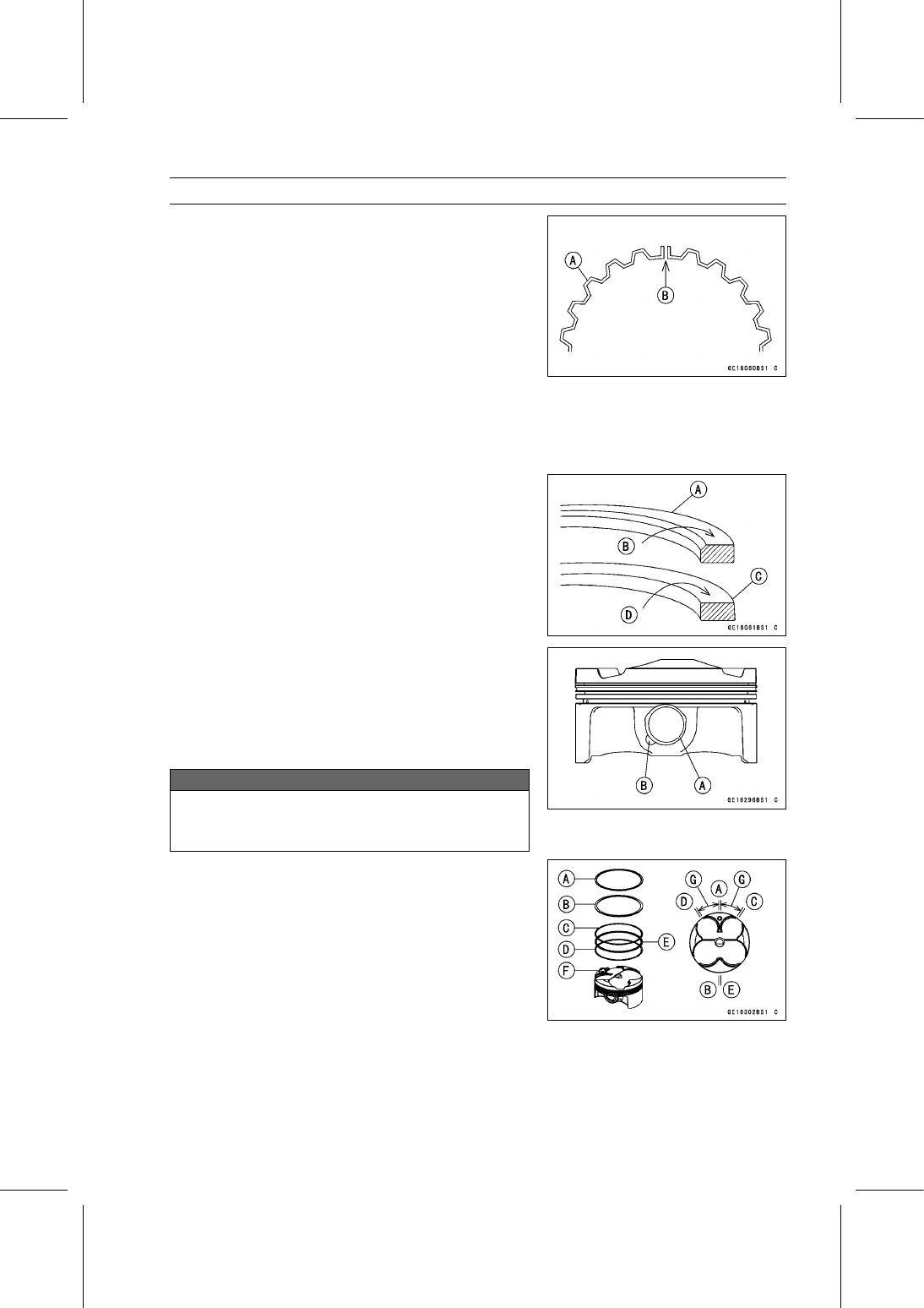
Apply molybdenum disulfide oil solution to the oil ring ex-
pander, and install the oil ring expander [A] in the bottom
piston ring groove so the ends [B] not butt together.

Apply molybdenum disulfide oil solution to the oil ring steel
rails, and install the oil ring steel rails, one above the ex-
pander and one below it.

Spread the rail with your thumbs, but only enough to fit
the rail over the piston.

Release the rail into the bottom piston ring groove.

NOTE

The oil ring rails have no “top” or “bottom”.

Apply molybdenum disulfide oil solution to the piston
rings.

NOTE

Do not mix up the top and second ring.

Install the top ring [A] so that the “R” mark [B] faces up.

Install the second ring [C] so that the “RN” mark [D] faces
up.

Apply molybdenum disulfide oil solution to the piston pins
and piston journals.

Fit a new piston pin snap ring into the side of the piston
so that the ring opening [A] does not coincide with the slit
[B] of the piston pin hole.

When installing the piston pin snap ring, compress it only
enough to install it and no more.

NOTICE

Do not reuse snap rings, as removal weakens and
deforms them. They could fall out and score the
cylinder wall.

The piston ring openings must be positioned as shown.
The openings of the oil ring steel rails must be about 30

40° of angle from the opening of the top ring.

Top Ring [A]
Second Ring [B]
Upper Oil Ring Steel Rail [C]
Lower Oil Ring Steel Rail [D]
Oil Ring Expander [E]
Dent [F]
30

40° [G]

9-30 CRANKSHAFT/TRANSMISSION

Pistons

Apply molybdenum disulfide oil solution to the cylinder
bore and piston skirt.

Install the piston with its dent mark [A] facing exhaust side.

Using the piston ring compressor assembly [B] to install
the piston from the cylinder head side.

Special Tools - Piston Ring Compressor Grip: 57001-1095

Piston Ring Compressor Belt,

67

79:

57001-1097

Install:

Crankshaft (see Crankshaft Installation)
Connecting Rod Big End Caps (see Connecting Rod In-
stallation)

Cylinder (Upper Crankcase) Wear Inspection

Since there is a difference in cylinder wear (upper
crankcase) in different directions, take a side-to-side and
a front-to-back measurement at each of the two locations
(total of four measurements) as shown.
If any of the cylinder inside diameter measurements ex-
ceeds the service limit, replace the crankcase.

10 mm (0.39 in.) [A]
60 mm (2.36 in.) [B]

Cylinder (Upper Crankcase) Inside Diameter

Standard:

67.000

67.012 mm (2.6378

2.6383 in.)

Service Limit: 67.09 mm (2.6413 in.)

Piston Wear Inspection

Measure the outside diameter [A] of each piston 5 mm
(0.20 in.) [B] up from the bottom of the piston at a right
angle to the direction of the piston pin.
If the measurement is under service limit, replace the pis-
ton.

Piston Diameter

Standard:

66.960

66.975 mm (2.6362

2.6368 in.)

Service Limit: 66.81 mm (2.6303 in.)

Piston Ring, Piston Ring Groove Wear Inspection

Check for uneven groove wear by inspecting the ring seat-
ing.
The rings should fit perfectly parallel to groove surfaces.
If not, replace the piston and all the piston rings.

With the piston rings in their grooves, make several mea-
surements with a thickness gauge [A] to determine piston
ring/groove clearance.

Piston Ring/Groove Clearance

Standard:

Top

0.03

0.07 mm (0.0012

0.0028 in.)

Second

0.03

0.07 mm (0.0012

0.0028 in.)

Service Limit:

Top

0.17 mm (0.0067 in.)

Second

0.17 mm (0.0067 in.)

CRANKSHAFT/TRANSMISSION 9-31

Pistons

Piston Ring Groove Width Inspection

Measure the piston ring groove width.

Use a vernier caliper at several points around the piston.

Piston Ring Groove Width

Standard:

Top [A]

0.82

0.84 mm (0.0323

0.0331 in.)

Second [B] 0.82

0.84 mm (0.0323

0.0331 in.)

Service Limit:

Top

0.92 mm (0.036 in.)

Second

0.92 mm (0.036 in.)

If the width of any of the two grooves is wider than the
service limit at any point, replace the piston.

Piston Ring Thickness Inspection

Measure the piston ring thickness.

Use the micrometer to measure at several points around
the ring.

Piston Ring Thickness

Standard:

Top [A]

0.77

0.79 mm (0.0303

0.0311 in.)

Second [B] 0.77

0.79 mm (0.0303

0.0311 in.)

Service Limit:

Top

0.70 mm (0.028 in.)

Second

0.70 mm (0.028 in.)

If any of the measurements is less than the service limit
on either of the rings, replace all the rings.

NOTE

When using new rings in a used piston, check for un-
even groove wear. The rings should fit perfectly parallel
to the groove sides. If not, replace the piston.

Piston Ring End Gap Inspection

Place the piston ring [A] inside the cylinder (upper
crankcase), using the piston to locate the ring squarely
in place. Set it close to the bottom of the cylinder, where
cylinder wear is low.

Measure the gap [B] between the ends of the ring with a
thickness gauge.

Piston Ring End Gap

Standard:

Top

0.12

0.22 mm (0.0047

0.0087 in.)

Second

0.30

0.45 mm (0.0118

0.0177 in.)

Service Limit:

Top

0.5 mm (0.020 in.)

Second

0.8 mm (0.031 in.)

If the end gap of either ring is greater than the service
limit, replace all the rings.

9-32 CRANKSHAFT/TRANSMISSION

Starter Idle Gear and Starter Clutch

Starter Idle Gear Removal

Remove:

Upper Fairing Assembly (see Upper Fairing Assembly
Removal in the Frame chapter)
Idle Gear Cover Bolts [A]
Idle Gear Cover [B]

Remove the idle gear (starter motor side) [A] with the shaft
[B].

Remove:

Starter Clutch Cover Bolts [A]
Starter Clutch Cover [B]

Remove the idle gear (starter clutch side) [A] with the
shaft [B].

Starter Idle Gear Installation

Apply molybdenum disulfide grease [A] to the idle gear
shaft (starter clutch side) [B].

Fit the pin [C] into the groove [D] of the crankcase.

CRANKSHAFT/TRANSMISSION 9-33

Starter Idle Gear and Starter Clutch

Install the idle gear (starter clutch side) [A] on the shaft.

Engage the idle gear with the starter clutch gear.

Using a high flash-point solvent, clean off any oil or dirt
that may be on the liquid gasket coating area. Dry them
with a clean cloth.

Apply liquid gasket to the following portion.

Crankshaft Sensor Lead Grommet [B]
Crankcase Halves Mating Surfaces [C]

Sealant - Liquid Gasket, TB1211F: 92104-0004

Install the dowel pins [D] and new gasket.

Apply grease to the O-ring of the starter motor.

Install the starter clutch cover [A].

Tighten:

Torque - Starter Clutch Cover Bolts: 9.8 N·m (1.0 kgf·m, 87

in·lb)

L = 30 mm (1.18 in.) [B]
L = 20 mm (0.79 in.) [C]

Apply molybdenum disulfide grease to the idle gear shaft
(starter motor side) [A].

Install the idle gear (starter motor side) [B] on the shaft.

Engage the idle gear with the starter motor gear and idle
gear (starter clutch side).

Fit the pin [C] into the groove [D] of the starter clutch cover.

Install the dowel pin [E] and new gasket.

Position the idle gear [A] to inside of the mating surface
[B] of the starter clutch cover.

Install:

Idle Gear Cover [A]
Idle Gear Cover Bolts [B]
Idle Gear Cover Bolts [C] with New Gaskets

Tighten:

Torque - Idle Gear Cover Bolts: 9.8 N·m (1.0 kgf·m, 87 in·lb)

Install the removed parts (see appropriate chapters).

9-34 CRANKSHAFT/TRANSMISSION

Starter Idle Gear and Starter Clutch

Starter Clutch Removal

Remove:

Alternator Cover (see Alternator Cover Removal in the
Electrical System chapter)
Starter Clutch Cover (see Starter Idle Gear Removal)
Idle Gear (Starter Clutch Side) (see Starter Idle Gear
Removal)

Remove the starter clutch bolt [A], while holding the al-
ternator rotor steady with the rotor holder (see Alternator
Rotor Removal in the Electrical System chapter).

Special Tools - Grip: 57001-1591

Rotor Holder: 57001-1666
Stopper: 57001-1679
Rotor Holder Attachment: 57001-1689

Remove:

Washer [B]
Starter Clutch [C]

Starter Clutch Installation

Install the starter clutch [A] on the crankshaft [B] with their
teeth [C] aligned.

Install the washer.

Tighten the starter clutch bolt, while holding the alternator
rotor steady with the rotor holder (see Alternator Rotor
Installation in the Electrical System chapter).

Special Tools - Grip: 57001-1591

Rotor Holder: 57001-1666
Stopper: 57001-1679
Rotor Holder Attachment: 57001-1689

Torque - Starter Clutch Bolt: 49 N·m (5.0 kgf·m, 36 ft·lb)

Install the removed parts (see appropriate chapters).

Starter Clutch Disassembly

Remove the starter clutch (see Starter Clutch Removal).

Remove the starter clutch gear [A] from the starter clutch
[B].

Remove the needle bearing [C].

Remove the snap ring [A].

Remove the one-way clutch [B] from the starter clutch
case [C].

CRANKSHAFT/TRANSMISSION 9-35

Starter Idle Gear and Starter Clutch

Starter Clutch Assembly

Install the one-way clutch [A] so that its circlip side [B]
faces inward.

Install the new snap ring.

Push the starter clutch gear [A] in and turn it counterclock-
wise [B] and install it.

Apply molybdenum disulfide oil solution to the needle
bearing [A], and install it.

Starter Clutch Inspection

Remove:

Starter Clutch Cover (see Starter Idle Gear Removal)
Idle Gear (Starter Clutch Side) (see Starter Idle Gear
Removal)

Turn the starter clutch gear [A] by hand. The starter clutch
gear should turn counterclockwise freely [B], but should
not turn clockwise.
If the starter clutch does not operate as it should or if it
makes noise, go to the next step.

Disassemble the starter clutch, and visually inspect the
clutch parts.

One-way Clutch [A]
Starter Clutch Case [B]

If there is any worn or damaged part, replace it.

9-36 CRANKSHAFT/TRANSMISSION

Starter Idle Gear and Starter Clutch

Examine the starter clutch gear [A] as well. Replace the
clutch gear if it is worn or damaged.

CRANKSHAFT/TRANSMISSION 9-37

Transmission

Transmission Assy Removal

Remove:

Engine Sprocket (see Engine Sprocket Removal in the
Final Drive chapter)
Gear Position Switch (see Gear Position Switch Re-
moval in the Electrical System chapter)
Collar [A]
O-ring [B]

Remove:

Clutch (see Clutch Removal in the Clutch chapter)
Shift Shaft Assembly (see External Shift Mechanism Re-
moval)
Transmission Case Bolts [A]

If the transmission assy is to be disassembled, remove
the following.

Gear Positioning Lever Bolt [B]
Gear Positioning Lever [C], Spring and Collar

Remove the transmission assy [D] from the crankcase.

Transmission Assy Disassembly

Remove the transmission assy (see Transmission Assy
Removal).

Remove the following from the transmission case [A].

Shift Rods [B]
Shift Forks [C]
Drive Shaft [D]
Output Shaft [E]

Remove:

Bearing Holder Screws [A]
Bearing Holder [B]
Shift Drum Assembly [C]

Transmission Assy Assembly

Press the race [A] in the transmission case [B] so that the
big stepped side [C] faces to transmission gears side until
it is bottomed.

Special Tool - Bearing Driver Set: 57001-1129

Install the race holder [D] as shown.

Apply a non-permanent locking agent to the threads of
the race holder screw [E].

Tighten:

Torque - Race Holder Screws: 4.9 N·m (0.50 kgf·m, 43 in·lb)

Install the dowel pins [F] in the transmission case until
they are bottomed.

9-38 CRANKSHAFT/TRANSMISSION

Transmission

Press the ball bearing [A] in the transmission case [B] so
that the stepped side faces outside until it is bottomed.

Special Tool - Bearing Driver Set: 57001-1129

Install the bearing holder [C] as shown.

Apply a non-permanent locking agent to the threads of
the bearing holder screws [D].

Tighten:

Torque - Bearing Holder Screws: 4.9 N·m (0.50 kgf·m, 43

in·lb)

Apply a non-permanent locking agent to the shift shaft
return spring pin.

Tighten:

Torque - Shift Shaft Return Spring Pin: 28 N·m (2.9 kgf·m,

21 ft·lb)

Install:

Shift Drum Assembly [A]
Bearing Holder [B]

Install the bearing holder so that the taper side faces out-
side.

Apply a non-permanent locking agent to the threads of
the bearing holder screws [C].

Tighten:

Torque - Bearing Holder Screws: 4.9 N·m (0.50 kgf·m, 43

in·lb)

CRANKSHAFT/TRANSMISSION 9-39

Transmission

Install the drive shaft [A] and output shaft [B] as a set in
the transmission case [C].

Install the shift forks as shown.

The shift fork [D] for drive shaft gears has the short ears.

The shift forks [E] [F] for output shaft gears have the long
ears.

The shift fork [E] has R mark [G].

The shift fork [F] has L mark [H].

Install the shift rods so that the ends of the rods are same
height.

The shift rod [I] of the drive shaft side is shorter than the
shift rod [J] of the output shaft side.

Apply molybdenum disulfide oil solution to the transmis-
sion gears (x marks) [K].

Install the spacer [L] on the output shaft.

Apply grease to the O-ring [M] and install it to its position
on the output shaft.

Transmission Assy Installation

Be sure that the dowel pins are in position.

Install the transmission assy on the crankcase.

Tighten:

Torque - Transmission Case Bolts (M8) [A]: 20 N·m (2.0

kgf·m, 15 ft·lb)

Transmission Case Bolts (M6) [B]: 9.8 N·m (1.0

kgf·m, 87 in·lb)

9-40 CRANKSHAFT/TRANSMISSION

Transmission

Install the gear positioning lever (see External Shift Mech-
anism Installation).

Set the gear positioning lever to the neutral position [A].

Check that the drive and output shaft turn freely.

Apply grease to the new O-ring [A] and install it to its po-
sition on the output shaft [B].

Install the collar [C].

When installing the oil seal [D], install it as follows.

Apply grease to the oil seal lips.

Apply soap and water solution to the outer circumference
of the oil seal so that it will go into place smoothly.

Press the oil seal to the crankcase so that the surface of
the oil seal is flush with the surface of the crankcase as
shown.

Install the removed parts (see appropriate chapters).

Transmission Shaft Removal

Refer to the Transmission Assy Disassembly.

Transmission Shaft Installation

Refer to the Transmission Assy Assembly.

Transmission Shaft Disassembly

Remove the transmission shafts (see Transmission Shaft
Removal).

Remove the circlips, and then disassemble the transmis-
sion shafts.

Special Tool - Outside Circlip Pliers: 57001-144

The 5th gear [A] on the output shaft has three steel balls
assembled into it for the positive neutral finder mecha-
nism. Remove the 5th gear.

Set the output shaft in a vertical position holding the 3rd
gear [B].

Spin the 5th gear quickly [C] and pull it off upward.

Transmission Shaft Assembly

Apply molybdenum disulfide oil solution to the sliding sur-
faces of the gears and shafts.

Install the gear bushings [A] on the shaft with their holes
[B] aligned.

CRANKSHAFT/TRANSMISSION 9-41

Transmission

Replace any circlips removed with new ones.

Install the circlip [A] on the drive shaft [B] so that the punch
mark [C] faces the washer [D] and position the opening [E]
as shown.

Install the circlip [A] on the output shaft [B] so that the
punch mark [C] faces the washer [D] and position the
opening [E] as shown.

The drive shaft gears can be recognized by size: the gear
with the smallest diameter is 1st gear, and the largest one
is 6th gear. Be sure that all parts are put back in the cor-
rect sequence and all circlips and washers are properly in
place.

Install the 3rd/4th gear onto the drive shaft with their oil
holes aligned.

Install the 5th and 6th gear bushings onto the drive shaft
with their oil holes aligned.

The output shaft gears can be recognized by size: the
gear with the largest diameter is 1st gear, and the small-
est one is 6th gear. Be sure that all parts are put back
in the correct sequence and all circlips and washers are
properly in place.

Install the 6th gears onto the output shaft with their oil
holes aligned.

Install the 1st, 2nd and 3rd/4th gear bushings onto the
output shaft with their oil holes aligned.

9-42 CRANKSHAFT/TRANSMISSION

Transmission

Fit the steel balls into the 5th gear holes in the output
shaft.

5th Gear [A]
Output Shaft [B]
Steel Balls [C]

NOTICE

Do not apply grease to the balls to hold them in
place. This will cause the positive neutral finder
mechanism to malfunction.

After assembling the 5th gear with steel balls in place on
the output shaft, check the ball-locking effect that the 5th
gear does not come out of the output shaft when moving
it up and down by hand.

Check that each gear spins or slides freely on the trans-
mission shafts without binding after assembly.

CRANKSHAFT/TRANSMISSION 9-43

Transmission

1. 1st Gear
2. 2nd Gear
3. 3rd Gear
4. 4th Gear
5. 5th Gear
6. 6th (Top) Gear
7. Drive Shaft
8. Output Shaft
9. O-ring

10. Spacer

11. Bushing

12. Washer,

40 mm (1.57 in.)

13. Bushing

14. Toothed Washer,

40 mm (1.57 in.)

15. Circlip
16. Steel Ball
17. Bushing
18. Washer,

32 mm (1.26 in.)

19. Needle Bearing
20. Circlip
21. Bushing
22. Toothed Washer,

34 mm (1.34 in.)

23. Circlip
24. Washer,

34 mm (1.34 in.)

25. Bushing

9-44 CRANKSHAFT/TRANSMISSION

Transmission

Shift Drum and Fork Removal

Refer to the Transmission Assy Disassembly.

Shift Drum and Fork Installation

Refer to the Transmission Assy Assembly.

Shift Drum Disassembly

Remove the shift drum (see Transmission Assy Disas-
sembly).

While holding the shift drum with a vise, remove the shift
drum cam holder bolt [A].

Remove:

Shift Drum Cam [B]
Dowel Pin [C]
Ball Bearings [D]
Shift Drum [E]

Shift Drum Assembly

Press the ball bearing [A] on the shift drum [B] until it is
bottomed.

Install:

Ball Bearing [C]
Dowel Pin [D] and Shift Drum Cam [E]

Align the pin with the groove in the shift drum cam.

Apply a non-permanent locking agent to the threads of
the shift drum cam holder bolt [F] and tighten it.

Torque - Shift Drum Cam Holder Bolt: 12 N·m (1.2 kgf·m,

106 in·lb)

Shift Fork Bending Inspection

Visually inspect the shift forks, and replace any fork that is
bent. A bent fork could cause difficulty in shifting, or allow
the transmission to jump out of gear when under power.

90° [A]

Shift Fork/Gear Groove Wear Inspection

Measure the thickness of the shift fork ears [A], and mea-
sure the width [B] of the gear grooves.
If the thickness of a shift fork ear is less than the service
limit, the shift fork must be replaced.

Shift Fork Ear Thickness

Standard:

5.9

6.0 mm (0.232

0.236 in.)

Service Limit: 5.8 mm (0.228 in.)

If the gear groove is worn over the service limit, the gear
must be replaced.

Gear Groove Width

Standard:

6.05

6.15 mm (0.238

0.242 in.)

Service Limit: 6.25 mm (0.246 in.)

CRANKSHAFT/TRANSMISSION 9-45

Transmission

Shift Fork Guide Pin/Drum Groove Wear
Inspection

Measure the diameter of each shift fork guide pin [A], and
measure the width of each shift drum groove [B].
If the guide pin on any shift fork is less than the service
limit, the fork must be replaced.

Shift Fork Guide Pin Diameter

Standard:

5.9

6.0 mm (0.232

0.236 in.)

Service Limit: 5.8 mm (0.228 in.)

If any shift drum groove is worn over the service limit, the
drum must be replaced.

Shift Drum Groove Width

Standard:

6.05

6.20 mm (0.238

0.244 in.)

Service Limit: 6.3 mm (0.248 in.)

Gear Dog and Gear Dog Hole Damage Inspection

Visually inspect the gear dogs [A] and gear dog holes [B].
Replace any damaged gears or gears with excessively
worn dogs or dog holes.

9-46 CRANKSHAFT/TRANSMISSION

External Shift Mechanism

Shift Pedal Removal

Remove:

Shift Lever Bolt [A]
Shift Lever [B]

If the tie-rod is removed from the shift pedal and shift lever,
note the following.

The following portions have left-hand threads.

Shift Lever Side of Tie-Rod
Locknut [C] of Shift Lever Side
Ball Joint [D] of Shift Lever

Remove:

Shift Pedal Mounting Bolt [E]
Tie-Rod [F] and Shift Pedal [G]

Shift Pedal Installation

Apply grease to the sliding surface [A] on the shift pedal
mounting bolt [B].

Apply a non-permanent locking agent to the threads of
the shift pedal mounting bolt.

Install:

Washers [C]
Tie-Rod [D] and Shift Pedal [E]

Tighten:

Torque - Shift Pedal Mounting Bolt: 25 N·m (2.5 kgf·m, 18

ft·lb)

Align the punch mark [A] on the shift shaft with the slit [B]
of the shift lever.

Tighten the shift lever bolt.

After installation, confirm that the shift pedal [C] is posi-
tioned as shown.

About 86° [D]
About 91° [E]
0

2 mm (0

0.08 in.) [F] (The distance between the

center line of the tie-rod [G] and center in the shift pedal
end.)

If the pedal position is different, adjust it as follows.

To adjust the pedal position, loosen the front locknut [H]
(left-hand threads) and rear locknut [I], and then turn the
tie-rod.

Tighten the locknuts securely.

External Shift Mechanism Removal

Remove:

Shift Lever (see Shift Pedal Removal)
Clutch (see Clutch Removal in the Clutch chapter)
Circlip [A]
Washer [B]

Special Tool - Outside Circlip Pliers: 57001-144

CRANKSHAFT/TRANSMISSION 9-47

External Shift Mechanism

Remove:

Shift Shaft Assembly [A]
Washer [B]

Remove:

Gear Positioning Lever Bolt [A]
Gear Positioning Lever [B]
Collar and Spring [C]

External Shift Mechanism Installation

Install the gear positioning lever [A] as shown.

Install:

Spring [B]
Collar [C]

Tighten:

Torque - Gear Positioning Lever Bolt [D]: 12 N·m (1.2 kgf·m,

106 in·lb)

Replace the oil seal [A] with a new one.

Apply grease to the lips of the grease seal.

Install:

Shift Shaft Assembly [A] and Washer

Fit the hole [B] and return spring pin [C].

9-48 CRANKSHAFT/TRANSMISSION

External Shift Mechanism

Replace the circlip [A] with a new one.

Install:

Circlip

Special Tool - Outside Circlip Pliers: 57001-144

Fit the circlip into the groove of the shift shaft securely.

Install the removed parts (see appropriate chapters).

External Shift Mechanism Inspection

Examine the shift shaft [A] for any damage.
If the shaft is bent, straighten or replace it.
If the serration [B] is damaged, replace the shaft.
If the springs [C] are damaged in any way, replace them.
If the shift mechanism arm [D] is damaged in any way,
replace the shaft.

Check the return spring pin [A] is not loose.
If it is loose, unscrew it, apply a non-permanent locking
agent to the threads, and tighten it.

Torque - Shift Shaft Return Spring Pin: 28 N·m (2.9 kgf·m,

21 ft·lb)

Check the gear positioning lever [B] and spring [C] for
breaks or distortion.
If the lever or spring are damaged in any way, replace
them.

Visually inspect the shift drum cam [D].
If they are badly worn or if they show any damage, replace
it.

WHEELS/TIRES 10-1

10

Wheels/Tires

Table of Contents

Exploded View........................................................................................................................

10-2

Specifications .........................................................................................................................

10-4

Special Tools ..........................................................................................................................

10-5

Wheels (Rims) ........................................................................................................................

10-6

Front Wheel Removal .......................................................................................................

10-6

Front Wheel Installation ....................................................................................................

10-6

Rear Wheel Removal........................................................................................................

10-7

Rear Wheel Installation.....................................................................................................

10-8

Wheel Inspection ..............................................................................................................

10-9

Axle Inspection..................................................................................................................

10-10

Balance Inspection............................................................................................................

10-10

Balance Adjustment ..........................................................................................................

10-10

Balance Weight Removal..................................................................................................

10-11

Balance Weight Installation...............................................................................................

10-11

Tires........................................................................................................................................

10-13

Air Pressure Inspection/Adjustment..................................................................................

10-13

Tire Inspection ..................................................................................................................

10-13

Tire Removal.....................................................................................................................

10-13

Tire Installation..................................................................................................................

10-13

Tire Repair ........................................................................................................................

10-15

Hub Bearing............................................................................................................................

10-16

Hub Bearing Removal.......................................................................................................

10-16

Hub Bearing Installation....................................................................................................

10-16

Hub Bearing Inspection.....................................................................................................

10-16

Hub Bearing Lubrication ...................................................................................................

10-17

10-2 WHEELS/TIRES

Exploded View

WHEELS/TIRES 10-3

Exploded View

Torque

No.

Fastener

N·m

kgf·m

ft·lb

Remarks

1

Front Axle Clamp Bolts

20

2.0

15

AL

2

Front Axle

127

13.0

93.7

3

Rear Axle Nut

127

13.0

93.7

AL: Tighten the two clamp bolts alternately two times to ensure even tightening torque.

HG: Apply high-temperature grease.

R: Replacement Parts

WL: Apply soap and water solution or rubber lubricant.

10-4 WHEELS/TIRES

Specifications

Item

Standard

Service Limit

Wheels (Rims)

Rim Runout:

Axial

TIR 0.3 mm (0.01 in.) or less

TIR 1.0 mm (0.04 in.)

Radial

TIR 0.5 mm (0.02 in.) or less

TIR 1.0 mm (0.04 in.)

Axle Runout/100 mm (3.94 in.) TIR 0.03 mm (0.0012 in.) or less

TIR 0.2 mm (0.008 in.)

Wheel Balance

10 g (0.35 oz.) or less

– – –

Balance Weights

10 g (0.35 oz.), 20 g (0.71 oz.),
30 g (1.06 oz.)

– – –

Rim Size:

Front

J17MC × MT3.50

– – –

Rear

J17MC × MT5.50

– – –

Tires

Air Pressure (when Cold):

Front

Up to 180 kg (397 lb) load:

– – –

250 kPa (2.50 kgf/cm², 36 psi)

Rear

Up to 180 kg (397 lb) load:

– – –

290 kPa (2.90 kgf/cm², 42 psi)

Tread Depth:

Front

3.6 mm (0.14 in.)

1 mm (0.04 in.)

(AT, CH, DE) 1.6 mm (0.06 in.)

Rear

5.1 mm (0.20 in.)

Up to 130 km/h (80 mph):

2 mm (0.08 in.)

Over 130 km/h (80 mph):

3 mm (0.12 in.)

Standard Tires:

Make, Type

Size

Front

BRIDGESTONE, BATTLAX
HYPERSPORT S20F J

120/70ZR17 M/C (58W)

Rear

BRIDGESTONE, BATTLAX
HYPERSPORT S20R J

180/55ZR17 M/C (73W)

WARNING

Some replacement tires may adversely affect handling and cause an accident resulting in
serious injury or death. To ensure proper handling and stability, use only the recommended
standard tires for replacement, inflated to the standard pressure.

WHEELS/TIRES 10-5

Special Tools

Bearing Driver Set:
57001-1129

Jack:
57001-1238

Bearing Remover Head,

25 ×

28:

57001-1346

Bearing Remover Shaft,

13:

57001-1377

Jack Attachment:
57001-1608

10-6 WHEELS/TIRES

Wheels (Rims)

Front Wheel Removal

Remove:

Bolt [A]
Front Wheel Rotation Sensor [B]
Front Caliper Mounting Bolts [C] (Both Sides)
Front Caliper [D] (Both Sides)

Loosen:

Front Axle Clamp Bolts [A]
Front Axle [B]

Remove the lower fairings (see Lower Fairing Removal in
the Frame chapter).

Raise the front wheel off the ground.

Special Tools - Jack: 57001-1238

Jack Attachment: 57001-1608

Pull out the front axle to the right side and drop the front
wheel out of the front forks.

NOTICE

Do not lay the wheel down on one of the discs. This
can damage or warp the disc.

Place blocks un-

der the wheel so that the disc does not touch the
ground.

Front Wheel Installation

NOTE

The direction of the wheel rotation [A] is shown by an
arrow [B] on the wheel spoke.

Check the wheel rotation mark on the front wheel and
install it.

WHEELS/TIRES 10-7

Wheels (Rims)

Apply high-temperature grease to the grease seal lips.

Fit the collars [A] on the both sides of the hub.

The collars are identical.

Insert the front axle [B] from the right side.

Tighten:

Torque - Front Axle: 127 N·m (13.0 kgf·m, 93.7 ft·lb)

Front Axle Clamp Bolts [C]
Viewed from Rear [D]

Before tightening the front axle clamp bolts on the right
front fork leg, pump the front fork up and down 4 or 5
times to allow the right front fork leg to seat on the front
axle.

NOTE

Put a block in front of the front wheel to stop moving.

Tighten:

Torque - Front Axle Clamp Bolts: 20 N·m (2.0 kgf·m, 15 ft·lb)

NOTE

Tighten the two clamp bolts alternately two times to en-
sure even tightening torque.

Install the removed parts (see appropriate chapters).

Check the front brake effectiveness (see Brake Operation
Inspection in the Periodic Maintenance chapter).

WARNING

After servicing, it takes several applications of the
brake lever before the brake pads contact the disc,
which could result in increased stopping distance
and cause an accident resulting in injury or death.
Do not attempt to ride the motorcycle until a firm
brake lever is obtained by pumping the lever until
the pads are against the disc.

Rear Wheel Removal

Raise the rear wheel off the ground with the stand [A].

10-8 WHEELS/TIRES

Wheels (Rims)

Remove the rear wheel rotation sensor from the caliper
bracket (see Rear Wheel Rotation Sensor Removal in the
Brakes chapter).

Remove:

Cotter Pin [A]
Rear Axle Nut [B]
Washer [C]
Rear Axle [D] (from Right Side)

Remove the drive chain [A] from the rear sprocket toward
the left.

Move the rear wheel back and remove it.

NOTICE

Do not lay the wheel on the ground with the disc
facing down. This can damage or warp the disc.
Place blocks under the wheel so that the disc does
not touch the ground.

Rear Wheel Installation

Apply high-temperature grease to the grease seal lips.

Fit the collars on the both sides of the hub.

Left Side Collar [A]
Right Side Collar [B] (with Flange)

Engage the drive chain with the rear sprocket.

Install the caliper bracket [A] onto the stopper [B] of the
swingarm.

Insert the rear axle from the right side of the wheel.

Install the washer and rear axle nut.

Adjust the drive chain slack before tightening the rear
axle nut (see Drive Chain Slack Inspection in the Periodic
Maintenance chapter).

Tighten:

Torque - Rear Axle Nut: 127 N·m (13.0 kgf·m, 93.7 ft·lb)

Insert a new cotter pin [A].

NOTE

When inserting the cotter pin, if the slots in the nut do
not align with the cotter pin hole in the axle, tighten the
nut clockwise [B] up to next alignment.

It should be within 30 degrees.

Loosen once and tighten again when the slot goes past
the nearest hole.

WHEELS/TIRES 10-9

Wheels (Rims)

Bend the cotter pin [A] over the nut.

WARNING

A loose axle nut can lead to an accident resulting in
serious injury or death. Tighten the axle nut to the
proper torque and install a new cotter pin.

Install the rear wheel rotation sensor (see Rear Wheel
Rotation Sensor Installation in the Brakes chapter).

Check the rear brake effectiveness (see Brake Operation
Inspection in the Periodic Maintenance chapter).

WARNING

After servicing, it takes several applications of the
brake pedal before the brake pads contact the disc,
which could result in increased stopping distance
and cause an accident resulting in injury or death.
Do not attempt to ride the motorcycle until a firm
brake pedal is obtained by pumping the pedal until
the pads are against the disc.

Wheel Inspection

Raise the front/rear wheel off the ground.

Special Tools - Jack: 57001-1238

Jack Attachment: 57001-1608

Spin the wheel lightly, and check for roughness or binding.
If roughness or binding is found, replace the hub bearings
(see Hub Bearing Removal/Installation).

Inspect the wheel for small cracks, dents, bending, or
warp.
If there is any damage to the wheel, replace the wheel.

Remove the wheel, and support it with the tire by the axle.

Measure the rim runout, axial [A] and radial [B], with a dial
gauge.
If rim runout exceeds the service limit, check the hub bear-
ings (see Hub Bearing Inspection).
If the problem is not due to the bearings, replace the
wheel.

Rim Runout (with tire installed)

Standard:

Axial

TIR 0.3 mm (0.01 in.) or less

Radial

TIR 0.5 mm (0.02 in.) or less

Service Limit:

Axial

TIR 1.0 mm (0.04 in.)

Radial

TIR 1.0 mm (0.04 in.)

10-10 WHEELS/TIRES

Wheels (Rims)

WARNING

Damaged wheel parts may fail and cause an acci-
dent resulting in serious injury or death. Never at-
tempt to repair a damaged wheel part. If the wheel
part is damaged, it must be replaced with a new one.

Axle Inspection

Remove the front and rear axles (see Front/Rear Wheel
Removal).

Visually inspect the front and rear axle for damages.
If the axle is damaged or bent, replace it.

Place the axle in V blocks that are 100 mm (3.94 in.) [A]
apart, and set a dial gauge [B] on the axle at a point
halfway between the blocks. Turn [C] the axle to mea-
sure the runout. The difference between the highest and
lowest dial readings is the amount of runout.
If axle runout exceeds the service limit, replace the axle.

Axle Runout/100 mm (3.94 in.)

Standard:

TIR 0.03 mm (0.0012 in.) or less

Service Limit: TIR 0.2 mm (0.008 in.)

Balance Inspection

Remove the front and rear wheels (see Front/Rear Wheel
Removal).

Support the wheel so that it can be spun freely.

Spin the wheel lightly, and mark [A] the wheel at the top
when the wheel stops.

Repeat this procedure several times. If the wheel stops
of its own accord in various positions, it is well balanced.
If the wheel always stops in one position, adjust the wheel
balance (see Balance Adjustment).

Balance Adjustment

If the wheel always stops in one position, provisionally
attach a balance weight [A] on the rim at the marking using
adhesive tape.

Rotate the wheel 1/4 turn [B], and see whether or not the
wheel stops in this position. If it does, the correct balance
weight is being used.
If the wheel rotates and the weight goes up, replace the
weight with the next heavier size. If the wheel rotates and
the weight goes down, replace the weight with the next
lighter size. Repeat these steps until the wheel remains
at rest after being rotated 1/4 turn.

Rotate the wheel another 1/4 turn and then another 1/4
turn to see if the wheel is correctly balanced.

Repeat the entire procedure as many times as necessary
to achieve correct wheel balance.

Permanently install the balance weight.

WHEELS/TIRES 10-11

Wheels (Rims)

Balance Weight Removal

Insert standard tip screwdrivers [A] [B] between the rib [C]
and weight [D] as shown.

Pry the balance weight with two screwdrivers and remove
the balance weight.

Discard the used balance weight.

NOTICE

Do not tap the screwdrivers. The rim could be dam-
aged.

Balance Weight Installation

Check if the weight portion has any play on the blade [A]
and clip [B].
If it does, discard it.

WARNING

Unbalanced wheels can create an unsafe riding
condition. If the balance weight has any play on
the rib of the rim, the blade and/or clip have been
stretched. Replace the loose balance weight. Do
not reuse used balance weight.

Balance Weight

Part Number

Weight

41075-0007

10 g (0.35 oz.)

41075-0008

20 g (0.71 oz.)

41075-0009

30 g (1.06 oz.)

NOTE

Balance weights are available from Kawasaki dealers
in 10, 20 and 30 grams (0.35, 0.71 and 1.06 oz.) sizes.
An imbalance of less than 10 grams (0.35 oz.) will not
usually affect running stability.

Do not use four or more balance weight (more than 90
gram, 3.2 oz.). If the wheel requires an excess balance
weight, disassemble the wheel to find the cause.

Slip the balance weight [A] onto the rib [B] by pushing or
lightly hammering [C] the clip [D].

Left Side [E]
Right Side [F]

10-12 WHEELS/TIRES

Wheels (Rims)

Be sure to install the balance weight.

Check that the blade [A] and clip [B] are fully seated on
the rim [C] and that the clip is hooked over the rib [D].

Left Side [E]
Right Side [F]


Content      ..     9      10      11      12     ..