Kawasaki Motorcycle Ninja ZX-6R / Ninja ZX-6R ABS. Service Manual (2013 year) - page 15
 

  Index      Manuals     Kawasaki Motorcycle Ninja ZX-6R / Ninja ZX-6R ABS. Service Manual (2013 year)


Search            copyright infringement  


Content      ..     13      14      15      16     ..


Kawasaki Motorcycle Ninja ZX-6R / Ninja ZX-6R ABS. Service Manual (2013 year) - page 15


SUSPENSION 13-27

Swingarm

Swingarm Removal

Remove:

Rear Wheel (see Rear Wheel Removal in the
Wheels/Tires chapter)
Chain Cover (see Drive Chain Removal in the Final Drive
chapter)
Engine Sprocket (see Engine Sprocket Removal in the
Final Drive chapter)
Mud Guard (see Mud Guard Removal in the Frame
chapter)
Rear Shock Absorber (see Rear Shock Absorber Re-
moval)
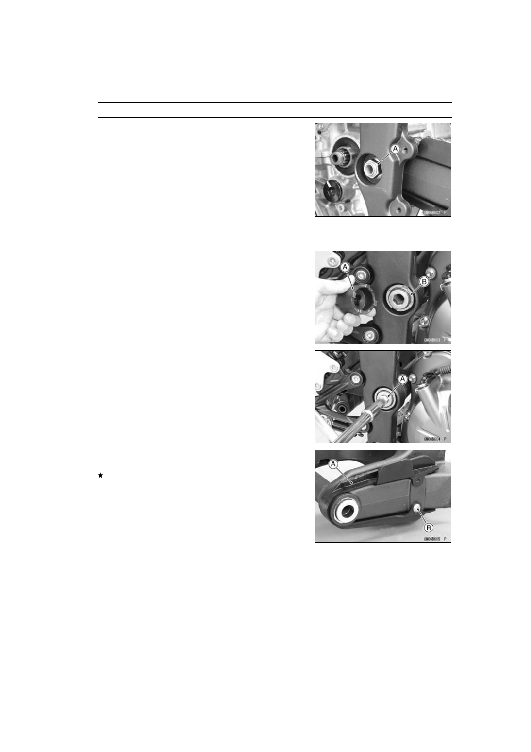
Swingarm Pivot Shaft Nut [A]

Using the swingarm pivot nut wrench [A], loosen the
swingarm pivot adjusting collar locknut [B].

Special Tool - Swingarm Pivot Nut Wrench: 57001-1597

Turn the swingarm pivot shaft [A] counterclockwise to free
the adjusting collar from the swingarm.

Make the gap between the adjusting collar and swingarm.

Pull out the pivot shaft to the right side and remove the
swingarm.

Swingarm Installation

Visually inspect the chain guide [A].
Replace the chain guide if it shows any signs of abnormal
wear or damage.

Apply a non-permanent locking agent to the threads of
the chain guide bolt [B].

13-28 SUSPENSION

Swingarm

Apply plenty of grease to the lip of the oil seals [A].

Be sure to install the oil seals and sleeve [B] to the
swingarm.

Fit the collar [C] on the oil seal of the left side.

Screw the adjusting collar [A] into the frame [B] so that the
collar does not project the swingarm mating surface [C].

Insert the swingarm pivot shaft [A] into the adjusting collar
[B] from the right side, and tighten the pivot shaft.

NOTE

Tighten the swingarm pivot shaft until the clearance [C]
between the ball bearing [D] and collar come to 0 mm
(0 in.).

Torque - Swingarm Pivot Shaft: 20 N·m (2.0 kgf·m, 15 ft·lb)

Using the swingarm pivot nut wrench, tighten the
swingarm pivot adjusting collar locknut [E].

Special Tool - Swingarm Pivot Nut Wrench: 57001-1597

Torque - Swingarm Pivot Adjusting Collar Locknut: 98 N·m

(10.0 kgf·m, 72 ft·lb)

Tighten the swingarm pivot shaft nut.

Torque - Swingarm Pivot Shaft Nut: 108 N·m (11.0 kgf·m,

79.7 ft·lb)

Install the removed parts (see appropriate chapters).

Swingarm Bearing Removal

Remove:

Swingarm (see Swingarm Removal)
Collar [A]
Oil Seals [B]
Sleeve [C]
Circlip [D] (Right Side)

Special Tool - Inside Circlip Pliers: 57001-143

SUSPENSION 13-29

Swingarm

Remove the ball bearing and needle bearings.

Special Tool - Oil Seal & Bearing Remover [A]: 57001-1058

Swingarm Bearing Installation

Replace the ball and needle bearings [A] with new ones.

Install the ball and needle bearings so that the manufac-
turer’s marks face out.

Special Tools - Bearing Driver Set: 57001-1129

Needle Bearing Driver,

28 [B]: 57001-1610

Spacer,

28: 57001-1637

Needle Bearing Driver,

20 & Spacer,

28:

57001-1678

Install the needle bearings [A], ball bearing [B] and oil
seals [C] position as shown.

Circlip [D]
32.5 mm (1.28 in.) [E]
0.5 mm (0.02 in.) [F]
19.5 mm (0.77 in.) [G]
9.5 mm (0.37 in.) [H]
2 mm (0.08 in.) [I]
Left Side [J]
Right Side [K]

13-30 SUSPENSION

Swingarm

Swingarm Bearing, Sleeve Inspection

NOTICE

Do not remove the bearings for inspection.

Re-

moval may damage them.

Inspect the needle bearings [A] and ball bearing installed
in the swingarm.

The rollers and ball in a bearing normally wear very little,
and wear is difficult to measure. Instead of measuring,
visually inspect the bearing for abrasion, discoloration, or
other damage.
If the needle bearing, and sleeve [B] show any sings of
abnormal wear, discoloration, or damage, replace them
as a set.

Turn the bearing in the swingarm back and forth [A] while
checking for plays, roughness, or binding.
If bearing play, roughness, or binding is found, replace
the bearing.

Examine the bearing seal [B] for tears or leakage.
If the seal is torn or is leaking, replace the bearing.

Swingarm Bearing Lubrication

NOTE

Since the bearing are packed with grease and sealed,
lubrication is not required.

SUSPENSION 13-31

Tie-Rod, Rocker Arm

Tie-Rod Removal

Remove:

Lower Fairings (see Lower Fairing Removal in the Frame
chapter)
Premuffler Chamber (see Premuffler Chamber Removal
in the Engine Top End chapter)

Squeeze the brake lever slowly and hold it with a band
[A].

WARNING

Motorcycle may fall over unexpectedly resulting in
an accident or injury. Be sure to hold the front brake
when removing the tie-rod.

Raise the rear wheel off the ground with the jack.

Special Tools - Jack: 57001-1238

Jack Attachment: 57001-1608

Remove:

Upper Tie-Rod Nut [A] and Bolt
Lower Tie-Rod Nut [B] and Bolt
Tie-Rods [C]

Tie-Rod Installation

Apply grease to the inside of the oil seals.

Install the tie-rods so that the marked side faces [A] out-
side.

Replace the tie-rod nuts with new ones.

Tighten:

Torque - Tie-Rod Nuts: 59 N·m (6.0 kgf·m, 44 ft·lb)

Install the removed parts (see appropriate chapters).

Rocker Arm Removal

Remove:

Lower Fairings (see Lower Fairing Removal in the Frame
chapter)
Premuffler Chamber (see Premuffler Chamber Removal
in the Engine Top End chapter)

Squeeze the brake lever slowly and hold it with a band
[A].

WARNING

Motorcycle may fall over unexpectedly resulting in
an accident or injury. Be sure to hold the front brake
when removing the rocker arm.

Raise the rear wheel off the ground with the jack.

Special Tools - Jack: 57001-1238

Jack Attachment: 57001-1608

13-32 SUSPENSION

Tie-Rod, Rocker Arm

Remove:

Lower Rear Shock Absorber Nut [A] and Bolt
Lower Tie-Rod Nut [B] and Bolt
Rocker Arm Nut [C] and Bolt
Rocker Arm [D]

Rocker Arm Installation

Apply grease to the inside of the oil seals [A].

Be sure to install the oil seals and sleeves [B] to the rocker
arm.

Replace the following nuts with new ones.

Rear Shock Absorber Nut (Lower)
Tie-Rod Nut (Lower)
Rocker Arm Nut

Tighten:

Torque - Rocker Arm Bolt: 34 N·m (3.5 kgf·m, 25 ft·lb)

Tie-Rod Nuts: 59 N·m (6.0 kgf·m, 44 ft·lb)
Lower Rear Shock Absorber Nut: 34 N·m (3.5

kgf·m, 25 ft·lb)

Install the removed parts (see appropriate chapters).

SUSPENSION 13-33

Tie-Rod, Rocker Arm

Tie-Rod and Rocker Arm Bearing Removal

Remove:

Tie-Rods (see Tie-Rod Removal)
Rocker Arm (see Rocker Arm Removal)
Swingarm [A] (see Swingarm Removal)
Sleeves [B]
Oil Seals [C]

Remove the needle bearings [D], using the suitable tool.

Tie-Rod and Rocker Arm Bearing Installation

Replace the needle bearings and oil seals with new ones.

Apply plenty of grease to the lips of the oil seals.

Install the needle bearings and oil seals position as
shown.

13-34 SUSPENSION

Tie-Rod, Rocker Arm

Screw the needle bearing driver [A] into the driver holder
[B].

NOTE

For a bearing of inside diameter

18, select the press-

ing side of the needle bearing driver according to its
pressing depth.

Insert the needle bearing driver into the needle bearing
[C] and press the needle bearing into the housing until
the driver contacts the end surface of the housing.

Bearing Pressing Depth: 5.5 mm (0.22 in.) [D]
5.0 mm (0.20 in.) [E]
Spacer,

18 [F] Thickness: 0.5 mm (0.02 in.)

NOTE

When pressing in the needle bearings to the 5.5 mm
(0.22 in.) depth, adjust the pressing depth with the
spacer.

Install the needle bearings so that the marked side
faces out.

Special Tools - Bearing Driver Set: 57001-1129

Needle Bearing Driver,

17/ 18:

57001

-1609

Spacer,

18: 57001-1636

SUSPENSION 13-35

Tie-Rod, Rocker Arm

Needle Bearings [A]
Oil Seals [B]
Rear Shock Absorber [C]
Tie-Rods [D]
Rocker Arm [E]
Swingarm [F]
7.5 mm (0.30 in.) [G]
5.0 mm (0.20 in.) [H]
5.5 mm (0.22 in.) [I]
Front [J]
Right Side [K]
Left Side [L]

Rocker Arm/Tie-Rod Bearing, Sleeve Inspection

NOTICE

Do not remove the bearings for inspection.

Re-

moval may damage them.

Visually inspect the rocker arm, or tie-rod sleeves [A] and
needle bearings [B].

The rollers in a needle bearing normally wear very little,
and wear is difficult to measure. Instead of measuring,
inspect the bearing for abrasion, color change, or other
damage.
If there is any doubt as to the condition of any of the nee-
dle bearings or sleeve, replace the sleeve and needle
bearings as a set.

Rocker Arm/Tie-Rod Bearing Lubrication

NOTE

Since the bearings are packed with grease, lubrication
is not required.

STEERING 14-1

14

Steering

Table of Contents

Exploded View........................................................................................................................

14-2

Special Tools ..........................................................................................................................

14-4

Steering ..................................................................................................................................

14-5

Steering Inspection ...........................................................................................................

14-5

Steering Adjustment..........................................................................................................

14-5

Steering Stem.........................................................................................................................

14-6

Stem, Stem Bearing Removal...........................................................................................

14-6

Stem, Stem Bearing Installation........................................................................................

14-7

Steering Stem Bearing Lubrication ...................................................................................

14-9

Steering Stem Warp Inspection ........................................................................................

14-9

Stem Cap Deterioration, Damage Inspection ...................................................................

14-10

Handlebar ...............................................................................................................................

14-11

Handlebar Removal ..........................................................................................................

14-11

Handlebar Installation .......................................................................................................

14-12

14-2 STEERING

Exploded View

STEERING 14-3

Exploded View

Torque

No.

Fastener

N·m

kgf·m

ft·lb

Remarks

1

Handlebar Clamp Bolts

25

2.5

18

2

Handlebar Positioning Bolts

9.8

1.0

87 in·lb

L

3

Left Switch Housing Screws

3.5

0.36

31 in·lb

4

Right Switch Housing Screws

3.5

0.36

31 in·lb

5

Throttle Case Screws

3.5

0.36

31 in·lb

6

Steering Stem Head Bolt

78

8.0

58

L

7

Upper Front Fork Clamp Bolts

20

2.0

15

8

Steering Stem Nut

27

2.8

20

9

Lower Front Fork Clamp Bolts

23

2.3

17

AL

AD: Apply adhesive.

AL: Tighten the two clamp bolts alternately two times to ensure even tightening torque.

G: Apply grease.

L: Apply a non-permanent locking agent.

14-4 STEERING

Special Tools

Bearing Puller:
57001-135

Head Pipe Outer Race Press Shaft:
57001-1075

Steering Stem Nut Wrench:
57001-1100

Steering Stem Bearing Driver,

42.5:

57001-1344

Steering Stem Bearing Driver Adapter,

41.5:

57001-1345

Head Pipe Outer Race Driver,

55:

57001-1446

STEERING 14-5

Steering

Steering Inspection

Refer to the Steering Play Inspection in the Periodic Main-
tenance chapter.

Steering Adjustment

Refer to the Steering Play Adjustment in the Periodic
Maintenance chapter.

14-6 STEERING

Steering Stem

Stem, Stem Bearing Removal

Remove:

Fuel Tank (see Fuel Tank Removal in the Fuel System
(DFI) chapter)
Upper Fairing Assembly (see Upper Fairing Assembly
Removal in the Frame chapter)
Front Wheel (see Front Wheel Removal in the
Wheels/Tires chapter)
Front Fender (see Front Fender Removal in the Frame
chapter)
Steering Stem Head with Handlebars (see Handlebar
Removal)
Front Forks (see Front Fork Removal in the Suspension
chapter)

For other than KIBS equipped models, remove the brake
hose fitting bolt from the steering stem.

Bend the claws [A] of the claw washer straighten.

Remove the steering stem locknut [B].

Special Tool - Steering Stem Nut Wrench: 57001-1100

Remove the claw washer.

Pushing up the stem base [A], and remove the steering
stem nut [B].

Special Tool - Steering Stem Nut Wrench [C]: 57001-1100

Remove:

Steering Stem
Stem Cap [D]
Washer
Upper Ball Bearing Inner Race and Ball Bearing

To remove the ball bearing outer races [A] pressed into
the head pipe [B], insert a bar [C] into the recesses of
head pipe, and applying it to both recess alternately ham-
mer it to drive the race out.

NOTE

If either steering stem bearing is damaged, it is recom-
mended that both the upper and lower bearings (includ-
ing outer races) should be replaced with new ones.

STEERING 14-7

Steering Stem

Remove the lower ball bearing [A] from the steering stem.

Remove the lower bearing inner race (with its grease seal)
[A] which is pressed onto the steering stem [B] with the
bearing puller [C], suitable collar [D] and adapter [E].

Special Tool - Bearing Puller: 57001-135

Stem, Stem Bearing Installation

Replace the bearing outer races with new ones.

Drive them into the head pipe at the same time.

Special Tools - Head Pipe Outer Race Press Shaft [A]:

57001-1075

Head Pipe Outer Race Driver,

55 [B]: 57001

-1446

Apply grease to the outer races.

Replace the bearing inner races and oil seal with new
ones.

Apply grease to the oil seal.

Install the oil seal [A] on the steering stem, and drive the
lower ball bearing inner race [B] applied the grease onto
the stem.

Special Tools - Steering Stem Bearing Driver,

42.5 [C]:

57001-1344

Steering Stem Bearing Driver Adapter,

41.5 [D]: 57001-1345

Apply grease to the lower ball bearing [A], and install it
onto the steering stem.

The lower and upper ball bearings are identical.

Apply grease to the upper ball bearing [B] and inner race
[C].

14-8 STEERING

Steering Stem

Install the steering stem [A] through the head pipe and
install the upper bearing [B] and inner race [C] on it.

Install:

Washer [D]
Stem Cap [E]
Steering Stem Nut [F]

Settle the bearings in place as follows.

Tighten the steering stem nut with

55 N·m (5.6 kgf·m, 41

ft·lb)

of torque first, and loosen it a fraction of a turn until

it turns lightly. Afterward tighten it again with specified
torque using a steering stem nut wrench [A].

Check that there is no play and the steering stem turns
smoothly without rattles. If not, the steering stem bearings
may be damaged.

Special Tool - Steering Stem Nut Wrench: 57001-1100

Torque - Steering Stem Nut: 27 N·m (2.8 kgf·m, 20 ft·lb)

STEERING 14-9

Steering Stem

Install the claw washer [A] so that its bent side [B] faces
upward, and engage the bent claws with the grooves of
stem locknut [C].

Hand tighten the stem locknut until it touches the claw
washer.

Hand tighten the stem locknut clockwise until the claws
are aligned with the second groove of stem nut [D], and
bend the 2 claws downward [E].

Install the stem head.

Apply a non-permanent locking agent to the threads of
the steering stem head bolt.

Install the washer, and temporary tighten the stem head
bolt.

Install the front forks (see Front Fork Installation in the
Suspension chapter).

NOTE

Tighten the upper front fork clamp bolts first, next the
stem head bolt, last the lower front fork clamp bolts.

Tighten the two lower front fork clamp bolts alternately
two times to ensure even tightening torque.

Torque - Upper Front Fork Clamp Bolts: 20 N·m (2.0 kgf·m,

15 ft·lb)

Steering Stem Head Bolt: 78 N·m (8.0 kgf·m, 58

ft·lb)

Lower Front Fork Clamp Bolts: 23 N·m (2.3 kgf·m,

17 ft·lb)

Handlebar Clamp Bolts: 25 N·m (2.5 kgf·m, 18

ft·lb)

WARNING

If the handlebar does not turn to the steering stop it
may cause an accident resulting in injury or death.
Be sure the cables, harnesses and hoses are routed
properly and do not interfere with handlebar move-
ment (see Cable, Wire, and Hose Routing section in
the Appendix chapter).

Install the removed parts (see appropriate chapters).

Steering Stem Bearing Lubrication

Refer to the Steering Stem Bearing Lubrication in the Pe-
riodic Maintenance chapter.

Steering Stem Warp Inspection

Whenever the steering stem is removed, or if the steering
can not be adjusted for smooth action, check the steering
stem for straightness.
If the steering stem [A] is bent, replace the steering stem.

14-10 STEERING

Steering Stem

Stem Cap Deterioration, Damage Inspection

Replace the stem cap if its seal lip [A] shows damage.

STEERING 14-11

Handlebar

Handlebar Removal

Remove:

Clutch Lever Clamp Bolts [A]
Clutch Lever Assembly [B]
Left Switch Housing [C]
Handlebar Weight [D]
Left Handlebar Grip [E]

Remove:

Front Master Cylinder [A] (see Front Master Cylinder Re-
moval in the Brakes chapter)
Right Switch Housing [B]
Throttle Case [C]
Handlebar Weight [D]
Throttle Grip [E]

Loosen:

Upper Front Fork Clamp Bolt [A] (Both Sides)
Handlebar Clamp Bolt [B] (Both Sides)

Remove:

Steering Stem Head Bolt Plug [A]
Steering Stem Head Bolt [B] and Washer
Steering Stem Head [C] with Handlebars

Remove:

Handlebar Positioning Bolts [A]
Handlebars

14-12 STEERING

Handlebar

Handlebar Installation

Apply a non-permanent locking agent to the threads of
the handlebar positioning bolts and tighten them.

Torque - Handlebar Positioning Bolts: 9.8 N·m (1.0 kgf·m,

87 in·lb)

Install the steering stem head with handlebars.

Apply a non-permanent locking agent to the threads of
the steering stem head bolt.

Install the washer [A] and steering stem head bolt [B].

Tighten:

Torque - Steering Stem Head Bolt: 78 N·m (8.0 kgf·m, 58

ft·lb)

Upper Front Fork Clamp Bolts: 20 N·m (2.0 kgf·m,

15 ft·lb)

Handlebar Clamp Bolts: 25 N·m (2.5 kgf·m, 18

ft·lb)

NOTE

Tighten the steering stem head bolt before tightening
the upper front fork clamp bolts and handlebar clamp
bolts.

WARNING

If the handlebar does not turn to the steering stop it
may cause an accident resulting in injury or death.
Be sure the cables, harnesses and hoses are routed
properly and do not interfere with handlebar move-
ment (see Cable, Wire, and Hose Routing section in
the Appendix chapter).

Install the steering stem head bolt plug to the steering
stem head bolt.

Apply adhesive cement to the inside of the left handlebar
grip.

Install the left handlebar grip, throttle grip and left/right
handlebar weight.

Apply a non-permanent locking agent to the threads of
the handlebar weight bolts, and tighten them.

Install the left and right switch housings.

Fit the projection [A] into a hole [B] in the handlebar.

Tighten:

Torque - Switch Housing Screws: 3.5 N·m (0.36 kgf·m, 31

in·lb)

STEERING 14-13

Handlebar

Install the throttle cable tips [A].

Install the throttle case.

Fit the projection [B] into a hole [C] in the handlebar.

Tighten:

Torque - Throttle Case Screws: 3.5 N·m (0.36 kgf·m, 31

in·lb)

Install:

Clutch Lever Assembly (see Clutch Lever Installation in
the Clutch chapter)
Front Master Cylinder (see Front Master Cylinder Instal-
lation in the Brakes chapter)

FRAME 15-1

15

Frame

Table of Contents

Exploded View...................................

15-2

Seats .................................................

15-8

Front Seat Removal .....................

15-8

Front Seat Installation ..................

15-8

Rear Seat Removal......................

15-8

Rear Seat Installation...................

15-8

Fairings..............................................

15-9

Lower Fairing Removal ................

15-9

Lower Fairing Installation .............

15-9

Lower Fairing Disassembly..........

15-9

Upper Fairing Assembly Removal

15-9

Upper Fairing Assembly

Installation .................................

15-11

Middle Fairing Removal ...............

15-11

Middle Fairing Installation ............

15-11

Center Fairing Removal/Installa-

tion ............................................

15-11

Inner Fairing Removal..................

15-12

Inner Fairing Installation...............

15-12

Fairing Cover Removal ................

15-12

Fairing Cover Installation .............

15-12

Side Covers .......................................

15-13

Inner Cover Removal ...................

15-13

Inner Cover Installation ................

15-13

Side Cover Removal ....................

15-13

Side Cover Installation .................

15-13

Tank Cover Removal....................

15-14

Tank Cover Installation.................

15-15

Seat Covers.......................................

15-16

Seat Cover Removal....................

15-16

Seat Cover Installation.................

15-16

Fenders .............................................

15-17

Front Fender Removal .................

15-17

Front Fender Installation ..............

15-17

Rear Fender Removal..................

15-17

Rear Fender Installation...............

15-18

Flap Removal...............................

15-19

Flap Installation............................

15-19

Frame ................................................

15-20

Rear Frame Rear Removal..........

15-20

Rear Frame Rear Installation.......

15-20

Rear Frame Front Removal .........

15-20

Rear Frame Front Installation ......

15-20

Frame Inspection .........................

15-20

Windshield .........................................

15-21

Windshield Removal ....................

15-21

Windshield Installation .................

15-21

Guard.................................................

15-22

Mud Guard Removal....................

15-22

Mud Guard Installation.................

15-22

Sidestand...........................................

15-23

Sidestand Removal......................

15-23

Sidestand Installation...................

15-23

15-2 FRAME

Exploded View

FRAME 15-3

Exploded View

Torque

No.

Fastener

N·m

kgf·m

ft·lb

Remarks

1

Rear Frame Bolts (M10)

44

4.5

32

L

2

Front Footpeg Bracket Bolts

25

2.5

18

L

3

Sidestand Switch Bolt

8.8

0.90

78 in·lb

L

4

Sidestand Bracket Bolts

49

5.0

36

L

5

Sidestand Nut

44

4.5

32

R, S

6

Sidestand Bolt

29

3.0

21

S

7

Rear Frame Bolts (M8)

25

2.5

18

L

8

Rear Footpeg Bracket Bolts

25

2.5

18

G: Apply grease.

L: Apply a non-permanent locking agent.

R: Replacement Parts

15-4 FRAME

Exploded View

FRAME 15-5

Exploded View

Torque

No.

Fastener

N·m

kgf·m

ft·lb

Remarks

1

Front Fender Mounting Bolts

3.9

0.40

35 in·lb

2. US, CA and CAL Models
L: Apply a non-permanent locking agent.

R: Replacements Parts

15-6 FRAME

Exploded View

FRAME 15-7

Exploded View

Torque

No.

Fastener

N·m

kgf·m

ft·lb

Remarks

1

Windshield Mounting Bolts

0.42

0.043

3.7 in·lb

15-8 FRAME

Seats

Front Seat Removal

Remove:

Side Covers (see Side Cover Removal)
Bolt [A] (Both Sides)

Remove the seat [B] forward while lifting up the front part
of the seat.

Front Seat Installation

Slip the seat hook [A] under the rib [B] on the rear frame
front.

Tighten the bolts.

Rear Seat Removal

Insert the ignition switch key [A] into the seat lock.

Pull up the front part of the seat [B] upward while turning
the key clockwise, and remove it forward.

Rear Seat Installation

Slip the seat hook [A] under the rib [B] on the rear frame
rear.

Insert the seat latches [C] into the latch holes [D].

Push down the seat until the lock clicks.


Content      ..     13      14      15      16     ..