Kawasaki Motorcycle Ninja ZX-6R / Ninja ZX-6R ABS. Service Manual (2013 year) - page 20
 

  Index      Manuals     Kawasaki Motorcycle Ninja ZX-6R / Ninja ZX-6R ABS. Service Manual (2013 year)


Search            copyright infringement  


Content      ..     18      19      20      21     ..


Kawasaki Motorcycle Ninja ZX-6R / Ninja ZX-6R ABS. Service Manual (2013 year) - page 20


SELF-DIAGNOSIS SYSTEM 17-9

Self-Diagnosis

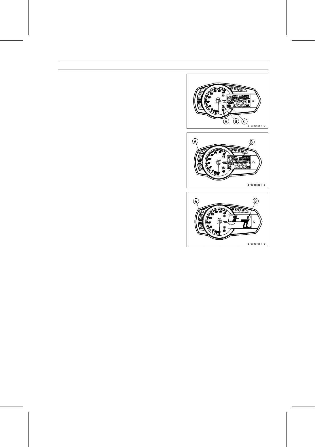
For models equipped with ABS system (equipped mod-
els), the yellow ABS indicator light (LED) [A] goes on,
when a problem occurs in the system. However, when
the yellow ABS indicator light (LED) goes off after the mo-
torcycle runs at approx. 5 km/h (3.1 mph) or above, the
ABS is normal.

For models equipped with KIBS system (equipped mod-
els), the yellow warning indicator light (LED) [B] and KIBS
warning symbol [C] go on, when a problem occurs in the
system.

Push the MODE button [A] to display the odometer [B].

Push the MODE button [A] for more than two seconds.

The service code [B] is displayed on the LCD by the num-
ber of two digits (The service code of the KIBS and ABS
adds “b" at the left side of the code.).

Any of the following procedures ends self-diagnosis.

When the service code is displayed on the LCD, push the
MODE button for more than two seconds. The display will
return to the odometer.

When the ignition switch is turned off.

17-10 SELF-DIAGNOSIS SYSTEM

Self-Diagnosis

Self-Diagnosis Flow Chart

SELF-DIAGNOSIS SYSTEM 17-11

Self-Diagnosis

Service Code Reading

The service code(s) is displayed on the LCD by the num-
ber of two digits. (The service code of the KIBS and ABS
adds “b" at the left side of the code.)

When there are a number of problems, all the service
codes can be stored and the display will begin starting
from the lowest number service code in the numerical or-
der.

Then after completing all codes, the display is repeated
until the ignition switch is turned off or MODE button is
pushed for more than two seconds.

The order of the system’s appearing is the order of DFI
System, Immobilizer System (equipped models), KTRC
System, KIBS and ABS (equipped models).

For example, if three problems occurred in the order of
56, 16, 33, the service codes are displayed (each two
seconds) from the lowest number in the order listed as
shown below.

(16

33

56)

(16

33

56)

→ →

····· (repeated)

If the no problem or when the repair has been done, yel-
low engine warning indicator light (LED) goes off and ser-
vice code is not displayed.

Service Code Erasing

When repair has been done, yellow engine warning indicator light (LED) goes off and service code
is not displayed.
The service codes stored in memory of the ECU can be erased using Kawasaki Diagnostic System
(KDS Ver.3).

Service Code Table

The service codes of the immobilizer, KIBS and ABS systems appear to each system equipped
models.

Service

Code

System

Problems

11

FI/KTRC

Main throttle sensor malfunction, wiring open or short

12

FI/KTRC

Intake air pressure sensor #1 malfunction, wiring open or short

13

FI

Intake air temperature sensor malfunction, wiring open or short

14

FI

Water temperature sensor malfunction, wiring open or short

16

FI/KTRC

Intake air pressure sensor #2 malfunction, wiring open or short

21

FI/KTRC

Crankshaft sensor malfunction, wiring open or short

24

FI/KTRC

Rear wheel rotation sensor signal abnormal (sensor or rotor missing,
too large clearance, rotor tooth worn or missing, wiring open)

25

FI/KTRC

Gear position switch malfunction, wiring open or short

27

FI/KTRC

Front wheel rotation sensor signal abnormal (sensor or rotor missing,
too large clearance, rotor tooth worn or missing, wiring open)

31

FI

Vehicle-down sensor malfunction, wiring open or short

32

FI/KTRC

Subthrottle sensor malfunction, wiring open or short

33

FI

Oxygen sensor inactivation, wiring open or short (Equipped Models)

34

FI

Exhaust butterfly valve actuator sensor malfunction, wiring open or
short

35

Immobilizer

Immobilizer amplifier malfunction (Equipped Models)

36

Immobilizer

Blank key detection (Equipped Models)

39

FI/KTRC

ECU communication error

17-12 SELF-DIAGNOSIS SYSTEM

Self-Diagnosis

Service

Code

System

Problems

51

FI/KTRC

Stick coil #1 malfunction, wiring open or short

52

FI/KTRC

Stick coil #2 malfunction, wiring open or short

53

FI/KTRC

Stick coil #3 malfunction, wiring open or short

54

FI/KTRC

Stick coil #4 malfunction, wiring open or short

56

FI

Radiator fan relay malfunction, wiring open or short

62

FI/KTRC

Subthrottle valve actuator malfunction, wiring open or short

63

FI

Exhaust butterfly valve actuator malfunction, wiring open or short

64

FI

Air switching valve malfunction, wiring open or short

67

FI

Oxygen sensor heater malfunction, wiring open or short (Equipped
Models)

94

FI

Oxygen sensor malfunction, wiring open or short (Equipped models)

1b

KIBS

KIBS hydraulic unit communication error (Equipped Models)

3A

FI

Purge valve malfunction, wiring open or short (CAL model)

b 13

ABS

Rear intake solenoid valve trouble (open, temperature abnormal)

b 14

ABS

Rear outlet solenoid valve trouble (open, temperature abnormal)

b 17

ABS

Front intake solenoid valve trouble (open, temperature abnormal)

b 18

ABS

Front outlet solenoid valve trouble (open, temperature abnormal)

b 19

ABS

KIBS solenoid valve relay trouble (wiring shorted or open, stuck relay
(ON or OFF) or dropout)

b 25

ABS

Front, rear wheel rotation difference abnormal (substandard tire,
sensor rotor teeth number wrong)

b 35

ABS

KIBS motor relay trouble [wiring shorted or open, stuck relay (ON or
OFF)]

b 42

ABS

Front wheel rotation sensor signal abnormal (sensor or rotor missing,
too large clearance, rotor tooth worn or missing)

b 43

ABS

Front wheel rotation sensor wiring (wiring shorted or open, connector
bad connection)

b 44

ABS

Rear wheel rotation sensor signal abnormal (sensor or rotor missing,
too large clearance, rotor tooth worn or missing)

b 45

ABS

Rear wheel rotation sensor wiring (wiring shorted or open, connector
bad connection)

b 52

ABS

Power supply voltage abnormal (under-voltage)

b 53

ABS

Power supply voltage abnormal (over-voltage)

b 55

ABS

ECU trouble (ECU operation abnormal)

b 57

KIBS

CAN communication (transmission)/CAN bus monitor malfunction

b 58

KIBS

CAN communication (reception) monitor malfunction

b 83

ABS

Output fluid pressure sensor (front brake) trouble (voltage abnormal,
wiring shorted or open)

b 84

ABS

Output fluid pressure sensor (front brake) trouble (offset abnormal)

b 89

ABS

Fluid pressure sensor supply voltage abnormal

SELF-DIAGNOSIS SYSTEM 17-13

Self-Diagnosis

Notes:

The ECU may be involved in these problems. If all the parts and circuits checked out good, be sure
to check the ECU for ground and power supply. If the ground and power supply are checked good,
replace the ECU.

When no service code is displayed, the electrical parts of the DFI system has no fault, and the
mechanical parts of the DFI system and the engine are suspect.

Backups

The ECU takes the following measures to prevent engine damage when the DFI, ignition, KTRC or
immobilizer system parts have troubles.

Service

Codes

Parts or

Function

Output Signal Usable

Range or Criteria

Backups by ECU

11

Main Throttle

Sensor

Output Voltage
0.2

4.8 V

If the main throttle sensor system fails (the
output voltage is out of the usable range,
wiring short or open), the ECU locks ignition
timing into the ignition timing at closed throttle
position and sets the DFI in the D-J method (1).

12

Intake Air

Pressure

Sensor #1

Intake Air Pressure
(Absolute)
Pv = 57

890 mmHg

If the intake air pressure sensor #1 system
fails (the signal is out of the usable range,
wiring short or open), the ECU sets the DFI
in the

α

-N method (2).

13

Intake Air

Temperature

Sensor

Intake Air Temperature
Ta = – 47

+ 178°C

If the intake air temperature sensor system
fails (the signal is out of the usable range,
wiring short or open), the ECU sets Ta at 30°C.

14

Water

Temperature

Sensor

Water Temperature
Tw = – 30

+ 120°C

If the water temperature sensor system fails
(the signal is out of the usable range, wiring
short or open), the ECU sets Tw at 80°C and
the radiator fan operates.

16

Intake Air

Pressure

Sensor #2

Atmospheric Pressure
(Absolute)
Pa = 57

890 mmHg

If the intake air pressure sensor #2 system
fails (the signal is out of the usable range,
wiring short or open), the ECU sets Pa at 760
mmHg (the standard atmospheric pressure).

21

Crankshaft

Sensor

Crankshaft sensor must
send 22 signals to the ECU
at the 1 cranking.

If the crankshaft sensor fails, the engine stops
by itself.

24

Rear Wheel

Rotation

Sensor

Rear wheel rotation sensor
must send 50 signals to
the ECU at the 1 rotation of
the wheel.

If the rear wheel rotation sensor system fails
(the signal is missing, wiring open), the ECU
stops the KTRC control.

25

Gear

Position

Switch

Output Voltage
0.51

4.73 V

If the gear position switch system fails (no
signal, wiring short or open), the ECU set the
top (6th) gear position.

27

Front Wheel

Rotation

Sensor

Signal

Front wheel rotation sensor
must send 48 signals to
the ECU at the 1 rotation of
the wheel.

If the front wheel rotation sensor system fails
(the signal is missing, wiring open), the ECU
stops the KTRC control.

31

Vehicle

-down

Sensor

Output Voltage
0.10

4.84 V

If the vehicle-down sensor system has failures
(the output voltage is out of the usable range,
wiring short or open), the ECU shuts off the
fuel pump relay, the fuel injectors and the
ignition system.

17-14 SELF-DIAGNOSIS SYSTEM

Self-Diagnosis

Service

Codes

Parts or

Function

Output Signal Usable

Range or Criteria

Backups by ECU

32

Subthrottle

Sensor

Output Voltage
0.15

4.85 V

If the subthrottle sensor system fails (the
output voltage is out of the usable range, wiring
short or open), the ECU drive the subthrottle
valve to the full closed position, and it stops
the current to the subthrottle valve actuator.

33

Oxygen

Sensor

(Equipped

Models)

The oxygen sensor is
active and sensor must
send signals (output
voltage) continuously to
the ECU.

If the oxygen sensor is not activated, the ECU
stops the feedback mode of the oxygen sensor.

34

Exhaust

Butterfly

Valve

Actuator

Sensor

Output Voltage 0.1

4.8 V

If the exhaust butterfly valve sensor system
fails (the output voltage is out of the usable
range, wiring short or open), the ECU locks
the exhaust butterfly valve at full open position
near, and it stops the current to the exhaust
butterfly valve actuator.

35

Immobilizer

Amplifier

(Equipped

Models)

If the immobilizer system fails (no signal, wiring
short or open), the vehicle is no start and run.

36

Ignition Key

The ignition key must use
register key.

If the blank key or broken key is used, the
vehicle is no start and run.

39

ECU

The ECU sends the data to
the meter unit through the
CAN communication line.

51

Stick Coil #1*

The ECU sends
signals (output voltage)
continuously to the stick
coil.

If the stick coil #1 primary winding has failures
(no signal, wiring short or open), the ECU
shuts off the injector #1 to stop fuel to the
cylinder #1, though the engine keeps running.

52

Stick Coil #2*

The ECU sends
signals (output voltage)
continuously to the stick
coil.

If the stick coil #2 primary winding has failures
(no signal, wiring short or open), the ECU
shuts off the injector #2 to stop fuel to the
cylinder #2, though the engine keeps running.

53

Stick Coil #3*

The ECU sends
signals (output voltage)
continuously to the stick
coil.

If the stick coil #3 primary winding has failures
(no signal, wiring short or open), the ECU
shuts off the injector #3 to stop fuel to the
cylinder #3, though the engine keeps running.

54

Stick Coil #4*

The ECU sends
signals (output voltage)
continuously to the stick
coil.

If the stick coil #4 primary winding has failures
(no signal, wiring short or open), the ECU
shuts off the injector #4 to stop fuel to the
cylinder #4, though the engine keeps running.

56

Radiator Fan

Relay

When the radiator fan relay
is OFF, the relay is opened.

62

Subthrottle

Valve

Actuator

The actuator operates
open and close of the
subthrottle valve by the
pulse signal from the ECU.

If the subthrottle valve actuator fails (the
signal is out to the usable range, wiring short
or open), the ECU stops the current to the
actuator.

SELF-DIAGNOSIS SYSTEM 17-15

Self-Diagnosis

Service

Codes

Parts or

Function

Output Signal Usable

Range or Criteria

Backups by ECU

63

Exhaust

Butterfly

Valve

Actuator

The actuator operates
open and close of the
exhaust butterfly valve by
the pulse signal from the
ECU.

If the exhaust butterfly valve actuator fails (the
signal is out to the usable range, wiring short
or open), the ECU stops the current to the
actuator.

64

Air Switching

Valve

The air switching valve
controls the flow of the
secondary air by opening
and shutting the solenoid
valve.

67

Oxygen

Sensor

Heater

(Equipped

Models)

The oxygen sensor heater
raises temperature of
the sensor for its earlier
activation.

If the oxygen sensor heater fails (wiring short
or open), the ECU stops the current to the
heater, and it stops the feedback mode of the
oxygen sensor.

94

Oxygen

Sensor

(Equipped

Models)

The oxygen sensor must
send signals (output
voltage) continuously to
the ECU

If the oxygen sensor output voltage is incorrect,
the ECU stops oxygen sensor feed back mode.

1b

KIBS

The KIBS hydraulic unit
sends the data (for status
of KIBS hydraulic unit)
to the meter unit and
ECU through the CAN
communication line.

If the communication data is not sent, the ECU
stops the KTRC control.

3A

Purge Valve

(CAL Model)

The purge valve controls
the flow of the secondary
air by opening and shutting
the solenoid valve.

Note:

(1): D-J Method: When the engine load is light like at idling or low speed, the ECU determines the

injection quantity by calculating from the throttle vacuum (vacuum sensor output voltage) and
engine speed (crankshaft sensor output voltage). This method is called D-J method.

(2):

α

-N Method: As the engine speed increases, and the engine load turns middle to heavy, the

ECU determines the injection quantity by calculating from the throttle opening (throttle sensor
output voltage) and the engine speed. This method is called

α

-N method.

*: This depends on the number of stopped cylinders.

17-16 SELF-DIAGNOSIS SYSTEM

Main Throttle Sensor (Service Code 11)

The main throttle sensor is a rotating variable resistor that

change output voltage according to throttle operating. The
ECU senses this voltage change and determines fuel injec-
tion quantity, and ignition timing according to engine rpm,
and throttle opening.

Input Terminal [A]: BL
Output Terminal [B]: Y/W
Ground Terminal [C]: G

Main Throttle Sensor Removal/Adjustment

NOTICE

Do not remove or adjust the main throttle sensor [A]
since it has been adjusted and set with precision at
the factory.
Never drop the throttle body assy especially on a
hard surface. Such a shock to the main throttle sen-
sor can damage it.

Main Throttle Sensor Input Voltage Inspection

NOTE

Be sure the battery is fully charged.

Turn the ignition switch off.

Remove the air cleaner housing (see Air Cleaner Housing
Removal in the Fuel System (DFI) chapter).

Disconnect the main throttle sensor connector [A].

Connect the setting adapter [A] between the harness con-
nector and main throttle sensor connector.

Special Tool - Throttle Sensor Setting Adapter:

57001

-1538

Connect a digital meter to the setting adapter leads.

Main Throttle Sensor Input Voltage

Connections to Adapter:

Digital Meter (+)

W (sensor BL) lead

Digital Meter (–)

BK (sensor G) lead

Measure the input voltage with the engine stopped and
with the connector joined.

Turn the ignition switch on.

Input Voltage

Standard:

DC 4.75

5.25 V

Turn the ignition switch off.
If the reading is within the standard, check the main throt-
tle sensor resistance (see Main Throttle Sensor Resis-
tance Inspection).

SELF-DIAGNOSIS SYSTEM 17-17

Main Throttle Sensor (Service Code 11)

If the reading is out of the standard, remove the ECU and
check the wiring for continuity between harness connec-
tors.

Special Tool - Hand Tester: 57001-1394

Disconnect the ECU and sensor connectors.

Wiring Continuity Inspection

ECU Connector [A]

←→

Main Throttle Sensor Connector [B]

BL lead (ECU terminal 4) [C]

G lead (ECU terminal 49) [D]

If the wiring is good, check the ECU for its ground and
power supply (see ECU Power Supply Inspection in the
Fuel System (DFI) chapter).
If the ground and power supply are good, replace the ECU
(see ECU Removal/Installation in the Fuel System (DFI)
chapter).

Main Throttle Sensor Resistance Inspection

Turn the ignition switch off.

Disconnect the main throttle sensor connector.

Connect a digital meter [A] to the main throttle sensor
connector [B].

Measure the main throttle sensor resistance.

Main Throttle Sensor Resistance

Connections:

BL lead [C]

← →

G lead [D]

Standard: 4

6 k

If the reading is out of the standard, replace the throttle
body assy.
If the reading is within the standard, check the output volt-
age (see Main Throttle Sensor Output Voltage Inspec-
tion).

Main Throttle Sensor Output Voltage Inspection

Measure the output voltage at the main throttle sensor in
the same way as input voltage inspection, note the follow-
ing.

Disconnect the main throttle sensor connector and con-
nect the setting adapter [A] between these connectors.

Special Tool - Throttle Sensor Setting Adapter:

57001

-1538

Main Throttle Sensor Output Voltage

Connections to Adapter:

Digital Meter (+)

R (sensor Y/W) lead

Digital Meter (–)

BK (sensor G) lead

Install the following parts temporarily.

Air Cleaner Housing (see Air Cleaner Housing Installa-
tion in the Fuel System (DFI) chapter)
Fuel Tank (see Fuel Tank Installation in the Fuel System
(DFI) chapter)

17-18 SELF-DIAGNOSIS SYSTEM

Main Throttle Sensor (Service Code 11)

Start the engine and warm it up thoroughly.

Check idle speed to ensure the throttle opening is correct
(see Idle Speed Inspection in the Periodic Maintenance
chapter).

Idle Speed

Standard:

1 300 ±50 r/min (rpm)

Turn the ignition switch off.

Measure the output voltage with the engine stopped, and
with the connector joined.

Turn the ignition switch on.

Output Voltage

Standard:

DC 1.02

1.06 V at idle throttle opening

DC 4.30

4.34 V at full throttle opening (for

reference)

NOTE

Open the throttle, confirm the output voltage will be
raise.

The standard voltage refers to the value when the volt-
age reading at the Input Voltage Inspection shows 5 V
exactly.

When the input voltage reading shows other than 5 V,
derive a voltage range as follows.
Example:
In the case of a input voltage of 4.75 V.
1.02 × 4.75 ÷ 5.00 = 0.969 V
1.04 × 4.75 ÷ 5.00 = 1.007 V
Thus, the valid range is 0.969

1.007 V

Turn the ignition switch off.
If the reading is out of the standard, replace the throttle
body assy.

If the reading is within the standard, remove the ECU and
check the wiring for continuity between harness connec-
tors.

Special Tool - Hand Tester: 57001-1394

Disconnect the ECU and sensor connectors.

Wiring Continuity Inspection

ECU Connector [A]

←→

Main Throttle Sensor Connector [B]

Y/W lead (ECU terminal 27) [C]

G lead (ECU terminal 49) [D]

If the wiring is good, check the ECU for its ground and
power supply (see ECU Power Supply Inspection in the
Fuel System (DFI) chapter).
If the ground and power supply are good, replace the ECU
(see ECU Removal/Installation in the Fuel System (DFI)
chapter).

SELF-DIAGNOSIS SYSTEM 17-19

Main Throttle Sensor (Service Code 11)

Main Throttle Sensor Circuit

1. ECU
2. Main Throttle Sensor
3. Subthrottle Sensor
4. Water-proof Joint 1
5. Water-proof Joint 2

17-20 SELF-DIAGNOSIS SYSTEM

Intake Air Pressure Sensor #1 (Service Code 12)

Intake Air Pressure Sensor #1 Removal

NOTICE

Never drop the intake air pressure sensor #1 espe-
cially on a hard surface. Such a shock to the sensor
can damage it.

Remove:

Air Cleaner Housing (see Air Cleaner Housing Removal
in the Fuel System (DFI) chapter)

Disconnect:

Intake Air Pressure Sensor #1 Connector [A]

Disconnect the intake air pressure sensor #1 [B] from the
bracket [C].

Disconnect the vacuum hose [A].

Remove the rubber damper [B] from the intake air pres-
sure sensor #1 [C].

Intake Air Pressure Sensor #1 Installation

NOTE

The intake air pressure sensor #1 is the same part as
the intake air pressure sensor #2.

Installation is basically the reverse of removal.

Position the intake air pressure sensor #1 [A] between the
projections [B] on the rubber damper.

Install the rubber damper [A] on the bracket [B].

SELF-DIAGNOSIS SYSTEM 17-21

Intake Air Pressure Sensor #1 (Service Code 12)

Intake Air Pressure Sensor #1 Input Voltage
Inspection

NOTE

Be sure the battery is fully charged.

Turn the ignition switch off.

Remove the air cleaner housing (see Air Cleaner Housing
Removal in the Fuel System (DFI) chapter).

Disconnect the intake air pressure sensor #1 connector
and connect the measuring adapter [A] between these
connectors.

[B] Main Harness
[C] Intake Air Pressure Sensor #1

Special Tool - Measuring Adapter: 57001-1700

Connect a digital meter [D] to the measuring adapter
leads.

Intake Air Pressure Sensor #1 Input Voltage

Connections to Adapter:

Digital Meter (+)

R (sensor BL) lead

Digital Meter (–)

BK (sensor G) lead

Measure the input voltage with the engine stopped and
with the connector joined.

Turn the ignition switch on.

Input Voltage

Standard:

DC 4.75

5.25 V

Turn the ignition switch off.
If the reading is within the standard, check the output volt-
age (see Intake Air Pressure Sensor #1 Output Voltage
Inspection).

If the reading is out of the standard, remove the ECU
and check the wiring for continuity between main harness
connectors.

Special Tool - Hand Tester: 57001-1394

Disconnect the ECU and sensor connectors.

Wiring Continuity Inspection

ECU Connector [A]

←→

Intake Air Pressure Sensor #1 Connector [B]

BL lead (ECU terminal 4) [C]

G lead (ECU terminal 49) [D]

If the wiring is good, check the ECU for its ground and
power supply (see ECU Power Supply Inspection in the
Fuel System (DFI) chapter).
If the ground and power supply are good, replace the ECU
(see ECU Removal/Installation in the Fuel System (DFI)
chapter).

17-22 SELF-DIAGNOSIS SYSTEM

Intake Air Pressure Sensor #1 (Service Code 12)

Intake Air Pressure Sensor #1 Output Voltage
Inspection

Measure the output voltage at the intake air pressure sen-
sor #1 in the same way as input voltage inspection, note
the following.

Disconnect the intake air pressure sensor #1 connector
and connect the measuring adapter [A] between these
connectors.

[B] Main Harness
[C] Intake Air Pressure Sensor #1
[D] Digital Meter

Special Tool - Measuring Adapter: 57001-1700

Intake Air Pressure Sensor #1 Output Voltage

Connections to Adapter:

Digital Meter (+)

Y (sensor Y/BL) lead

Digital Meter (–)

BK (sensor G) lead

Measure the output voltage with the engine stopped and
with the connector joined.

Turn the ignition switch on.

Output Voltage

Usable Range:

DC 3.80

4.20 V at standard

atmospheric pressure (101.32 kPa,
76 cmHg)

NOTE

The output voltage changes according to local atmo-
spheric pressure.

Turn the ignition switch off.
If the reading is out of the usable range, replace the sen-
sor.

If the reading is within the usable range, remove the ECU
and check the wiring for continuity between main harness
connector.

Special Tool - Hand Tester: 57001-1394

Disconnect the ECU and sensor connectors.

Wiring Continuity Inspection

ECU Connector [A]

←→

Intake Air Pressure Sensor #1 Connector [B]

Y/BL lead (ECU terminal 18) [C]

G lead (ECU terminal 49) [D]

SELF-DIAGNOSIS SYSTEM 17-23

Intake Air Pressure Sensor #1 (Service Code 12)

If the wiring is good, check the sensor for various vacuum.

Remove the intake air pressure sensor #1 [A] and discon-
nect the vacuum hose from the sensor.

Connect an auxiliary hose [B] to the intake air pressure
sensor #1.

Temporarily install the intake air pressure sensor #1.

Connect a digital meter [C], vacuum gauge [D], the fork oil
level gauge [E] and the measuring adapter to the intake
air pressure sensor #1.

Special Tools - Fork Oil Level Gauge: 57001-1290

Vacuum Gauge: 57001-1369
Measuring Adapter: 57001-1700

Intake Air Pressure Sensor #1 Output Voltage

Connections to Adapter:

Digital Meter (+)

Y (sensor Y/BL) lead

Digital Meter (–)

BK (sensor G) lead

Turn the ignition switch on.

Measure the intake air pressure sensor #1 output voltage
from various vacuum readings, while pulling the handle of
the fork oil level gauge.

Check the intake air pressure sensor #1 output voltage,
using the following formula and chart.

Suppose:

Pg: Vacuum Pressure (Gauge) of Throttle Body

Pl: Local Atmospheric Pressure (Absolute) measured by

a barometer

Pv: Vacuum Pressure (Absolute) of Throttle Body
Vv: Sensor Output Voltage (V)

then

Pv = Pl – Pg

For example, suppose the following data is obtained:

Pg = 8 cmHg (Vacuum Gauge Reading)

Pl = 70 cmHg (Barometer Reading)

Vv = 3.2 V (Digital Meter Reading)

then

Pv = 70 – 8 = 62 cmHg (Absolute)

Plot this Pv (62 cmHg) at a point [1] on the chart and draw a
vertical line through the point. Then, you can get the usable
range [2] of the sensor output voltage.

Usable range = 3.08

3.48 V

Plot Vv (3.2 V) on the vertical line.

Point [3].

Results: In the chart, Vv is within the usable range and
the sensor is normal.

If the reading is out of the usable range, replace the sen-
sor.
If the reading is within the usable range, check the ECU
for its ground and power supply (see ECU Power Supply
Inspection in the Fuel System (DFI) chapter).
If the ground and power supply are good, replace the ECU
(see ECU Removal/Installation in the Fuel System (DFI)
chapter).

17-24 SELF-DIAGNOSIS SYSTEM

Intake Air Pressure Sensor #1 (Service Code 12)

ID: Idling

Ps: Standard Atmospheric Pressure (Absolute)
Pv: Throttle Vacuum Pressure (Absolute)
ST: Standard of Sensor Output Voltage (V)

TO: Throttle Full Open

UR: Usable Range of Sensor Output Voltage (V)

Vv: Intake Air Pressure Sensor #1 Output Voltage (V) (Digital Meter Reading)

SELF-DIAGNOSIS SYSTEM 17-25

Intake Air Pressure Sensor #1 (Service Code 12)

Intake Air Pressure Sensor #1 Circuit

1. ECU
2. Water-proof Joint 2
3. Water-proof Joint 1
4. Intake Air Pressure Sensor #2
5. Intake Air Pressure Sensor #1

17-26 SELF-DIAGNOSIS SYSTEM

Intake Air Temperature Sensor (Service Code 13)

Intake Air Temperature Sensor Removal

NOTICE

Never drop the intake air temperature sensor espe-
cially on a hard surface. Such a shock to the sensor
can damage it.

Remove the fuel tank (see Fuel Tank Removal in the Fuel
System (DFI) chapter).

Disconnect the connector [A] from the intake air temper-
ature sensor.

Remove:

Screw [A]
Intake Air Temperature Sensor [B]

Intake Air Temperature Sensor Installation

Be sure to install the O-ring [A].

Install the intake air temperature sensor.

Tighten:

Torque - Intake Air Temperature Sensor Screw: 1.2 N·m

(0.12 kgf·m, 11 in·lb)

Connect the intake air temperature sensor lead connec-
tor.

SELF-DIAGNOSIS SYSTEM 17-27

Intake Air Temperature Sensor (Service Code 13)

Intake Air Temperature Sensor Output Voltage
Inspection

NOTE

Be sure the battery is fully charged.

Turn the ignition switch off.

Remove the fuel tank (see Fuel Tank Removal in the Fuel
System (DFI) chapter).

Disconnect the intake air temperature sensor connector
and connect the measuring adapter [A] between these
connectors as shown.

Main Harness [B]
Intake Air Temperature Sensor [C]

Special Tool - Measuring Adapter: 57001-1700

Connect a digital meter [D] to the harness adapter leads.

Intake Air Temperature Sensor Output Voltage

Connections to Adapter:

Digital Meter (+)

R (sensor R/BK) lead

Digital Meter (–)

BK (sensor G) lead

Measure the output voltage with the engine stopped and
the connector joined.

Turn the ignition switch on.

Output Voltage

Standard:

About DC 2.25

2.50 V at 20°C (68°F)

NOTE

The output voltage changes according to the intake air
temperature.

Turn the ignition switch off.
If the reading is within the standard, check the ECU for
its ground, and power supply (see ECU Power Supply
Inspection in the Fuel System (DFI) chapter).
If the ground and power supply are good, replace the ECU
(see ECU Removal/Installation in the Fuel System (DFI)
chapter).

If the reading is out of the standard, remove the ECU
and check the wiring for continuity between main harness
connectors.

Special Tool - Hand Tester: 57001-1394

Disconnect the ECU and sensor connectors.

Wiring Inspection

ECU Connector [A]

←→

Intake Air Temperature Sensor Connector [B]

R/BK lead (ECU terminal 16) [C]

G lead (ECU terminal 49) [D]

If the wiring is good, check the intake air temperature sen-
sor resistance (see Intake Air Temperature Sensor Resis-
tance Inspection).

17-28 SELF-DIAGNOSIS SYSTEM

Intake Air Temperature Sensor (Service Code 13)

Intake Air Temperature Sensor Resistance
Inspection

Remove the intake air temperature sensor (see Intake Air
Temperature Sensor Removal).

Suspend the sensor [A] in a container of machine oil so
that the heat-sensitive portion is submerged.

Suspend a thermometer [B] with the heat-sensitive por-
tion [C] located in almost the same depth with the sensor.

NOTE

The sensor and thermometer must not touch the con-
tainer side or bottom.

Place the container over a source of heat and gradually
raise the temperature of the oil while stirring the oil gently
for even temperature.

Using a digital meter, measure the internal resistance
of the sensor across the terminals at the temperatures
shown in the following.

Intake Air Temperature Sensor Resistance

Standard:

5.4

6.6 k

at 0°C (32°F)

0.29

0.39 k

at 80°C (176°F)

If the reading is out of the standard, replace the sensor.
If the reading is within the standard, but the problem still
exists, replace the ECU (see ECU Removal/Installation in
the Fuel System (DFI) chapter).

Intake Air Temperature Sensor Circuit

1. ECU
2. Water-proof Joint 2
3. Intake Air Temperature Sensor

SELF-DIAGNOSIS SYSTEM 17-29

Water Temperature Sensor (Service Code 14)

Water Temperature Sensor Removal/Installation

NOTICE

Never drop the water temperature sensor especially
on a hard surface. Such a shock to the sensor can
damage it.

Remove the throttle body assy (see Throttle Body Assy
Removal in the Fuel System (DFI) chapter).

Drain the coolant (see Coolant Change in the Periodic
Maintenance chapter).

Disconnect the water temperature sensor lead connector.

Remove:

Water Temperature Sensor [A] with O-ring

Replace the O-ring with a new one and apply soap and
water solution to it.

Tighten:

Torque - Water Temperature Sensor: 12 N·m (1.2 kgf·m, 106

in·lb)

Fill the engine with coolant and bleed the air from the cool-
ing system (see Coolant Change in the Periodic Mainte-
nance chapter).

Water Temperature Sensor Output Voltage
Inspection

NOTE

Be sure the battery is fully charged.

Turn the ignition switch off.

Remove the throttle body assy (see Throttle Body Assy
Removal in the Fuel System (DFI) chapter).

Disconnect the water temperature sensor connector and
connect the measuring adapter [A] between these con-
nectors as shown.

Main Harness [B]
Water Temperature Sensor [C]

Special Tool - Measuring Adapter: 57001-1700

Connect a digital meter [D] to the measuring adapter
leads.

Water Temperature Sensor Output Voltage

Connections to Adapter:

Digital Meter (+)

R (sensor W/G) lead

Digital Meter (–)

BK (sensor G) lead

Measure the output voltage with the engine stopped and
the connector joined.

Turn the ignition switch on.

Output Voltage

Standard:

About DC 2.80

2.97 V at 20°C (68°F)

NOTE

The output voltage changes according to the coolant
temperature in the engine.

17-30 SELF-DIAGNOSIS SYSTEM

Water Temperature Sensor (Service Code 14)

Turn the ignition switch off.
If the reading is within the standard, check the ECU for
its ground, and power supply (see ECU Power Supply
Inspection in the Fuel System (DFI) chapter).
If the ground and power supply are good, replace the ECU
(see ECU Removal/Installation in the Fuel System (DFI)
chapter).

If the reading is out of the standard, remove the ECU and
check the wiring for continuity between harness connec-
tors.

Special Tool - Hand Tester: 57001-1394

Disconnect the ECU and sensor connectors.

Wiring Continuity Inspection

ECU Connector [A]

←→

Water Temperature Sensor Connector [B]

W/G lead (ECU terminal 30) [C]

G lead (ECU terminal 49) [D]

If the wiring is good, check the water temperature sensor
resistance (see Water Temperature Sensor Resistance
Inspection).

Water Temperature Sensor Resistance Inspection

Refer to the Water Temperature Sensor Inspection in the
Electrical System chapter.
If the reading is within the standard, but the problem still
exists, replace the ECU (see ECU Removal/Installation in
the Fuel System (DFI) chapter).

Water Temperature Sensor Circuit

1. ECU
2. Water-proof Joint 2
3. Water Temperature Sensor

SELF-DIAGNOSIS SYSTEM 17-31

Intake Air Pressure Sensor #2 (Service Code 16)

Intake Air Pressure Sensor #2 Removal

NOTICE

Never drop the intake air pressure sensor #2 espe-
cially on a hard surface. Such a shock to the sensor
can damage it.

Remove:

Air Cleaner Housing (see Air Cleaner Housing Removal
in the Fuel System (DFI) chapter)

Disconnect:

Intake Air Pressure Sensor #2 Connector [A]

Disconnect the intake air pressure sensor #2 [B] from the
bracket [C].

Disconnect the vacuum hose [A].

Remove the rubber damper [B] from the intake air pres-
sure sensor #2 [C].

Intake Air Pressure Sensor #2 Installation

NOTE

The intake air pressure sensor #2 is the same part as
the intake air pressure sensor #1.

Installation is basically the reverse of removal.

Position the intake air pressure sensor #2 [A] between the
projections [B] on the rubber damper.

Install the rubber damper [A] on the bracket [B].

17-32 SELF-DIAGNOSIS SYSTEM

Intake Air Pressure Sensor #2 (Service Code 16)

Intake Air Pressure Sensor #2 Input Voltage
Inspection

NOTE

Be sure the battery is fully charged.

Turn the ignition switch off.

Remove the air cleaner housing (see Air Cleaner Housing
Removal in the Fuel System (DFI) chapter).

Disconnect the intake air pressure sensor #2 connector
and connect the measuring adapter [A] between these
connectors.

[B] Main Harness
[C] Intake Air Pressure Sensor #2

Special Tool - Measuring Adapter: 57001-1700

Connect a digital meter [D] to the measuring adapter
leads.

Intake Air Pressure Sensor #2 Input Voltage

Connections to Adapter:

Digital Meter (+)

R (sensor BL) lead

Digital Meter (–)

BK (sensor G) lead

Measure the input voltage with the engine stopped and
with the connector joined.

Turn the ignition switch on.

Input Voltage

Standard:

DC 4.75

5.25 V

Turn the ignition switch off.
If the reading is within the standard, check the output volt-
age (see Intake Air Pressure Sensor #2 Output Voltage
Inspection).

If the reading is out of the standard, remove the ECU
and check the wiring for continuity between main harness
connectors.

Special Tool - Hand Tester: 57001-1394

Disconnect the ECU and sensor connectors.

Wiring Continuity Inspection

ECU Connector [A]

←→

Intake Air Pressure Sensor #2 Connector [B]

BL lead (ECU terminal 4) [C]

G lead (ECU terminal 49) [D]

If the wiring is good, check the ECU for its ground and
power supply (see ECU Power Supply Inspection in the
Fuel System (DFI) chapter).
If the ground and power supply are good, replace the ECU
(see ECU Removal/Installation in the Fuel System (DFI)
chapter).

SELF-DIAGNOSIS SYSTEM 17-33

Intake Air Pressure Sensor #2 (Service Code 16)

Intake Air Pressure Sensor #2 Output Voltage
Inspection

Measure the output voltage at the intake air pressure sen-
sor #2 in the same way as input voltage inspection, note
the following.

Disconnect the intake air pressure sensor #2 connector
and connect the measuring adapter [A] between these
connectors.

[B] Main Harness
[C] Intake Air Pressure Sensor #2
[D] Digital Meter

Special Tool - Measuring Adapter: 57001-1700

Intake Air Pressure Sensor #2 Output Voltage

Connections to Adapter:

Digital Meter (+)

Y (sensor G/W) lead

Digital Meter (–)

BK (sensor G) lead

Measure the output voltage with the engine stopped and
with the connector joined.

Turn the ignition switch on.

Output Voltage

Usable Range: DC 3.80

4.20 V at standard

atmospheric pressure (101.32 kPa, 76
cmHg absolute)

NOTE

The output voltage changes according to the local at-
mospheric pressure.

Turn the ignition switch off.
If the reading is out of the usable range, replace the sen-
sor.

If the reading is within the usable range, remove the ECU
and check the wiring for continuity between main harness
connector.

Special Tool - Hand Tester: 57001-1394

Disconnect the ECU and sensor connectors.

Wiring Continuity Inspection

ECU Connector [A]

←→

Intake Air Pressure Sensor #2 Connector [B]

G/W lead (ECU terminal 17) [C]

G lead (ECU terminal 49) [D]

If the wiring is good, check the sensor for various vac-
uum (see Intake Air Pressure Sensor #1 Output Voltage
Inspection).

17-34 SELF-DIAGNOSIS SYSTEM

Intake Air Pressure Sensor #2 (Service Code 16)

Intake Air Pressure Sensor #2 Circuit

1. ECU
2. Water-proof Joint 2
3. Water-proof Joint 1
4. Intake Air Pressure Sensor #2
5. Intake Air Pressure Sensor #1

SELF-DIAGNOSIS SYSTEM 17-35

Crankshaft Sensor (Service Code 21)

The crankshaft sensor has no power source, and when

the engine stops, the crankshaft sensor generates no sig-
nals.

Crankshaft Sensor Removal/Installation

Refer to the Crankshaft Sensor Removal/Installation in
the Electrical System chapter.

Crankshaft Sensor Resistance Inspection

Refer to the Crankshaft Sensor Inspection in the Electrical
System chapter.
If the reading is within the standard, check the peak volt-
age (see Crankshaft Sensor Peak Voltage Inspection).

Crankshaft Sensor Peak Voltage Inspection

Refer to the Crankshaft Sensor Peak Voltage Inspection
in the Electrical System chapter.
If the reading is within the standard, remove the ECU and
check the wiring for continuity between harness connec-
tors.

Special Tool - Hand Tester: 57001-1394

Disconnect the ECU and sensor connectors.

Wiring Continuity Inspection

ECU Connector [A]

←→

Crankshaft Sensor Connector [B]

Y/BK lead (ECU terminal 59) [C]

Y lead (ECU terminal 60) [D]

If the wiring is good, check the ECU for its ground and
power supply (see ECU Power Supply Inspection in the
Fuel System (DFI) chapter).
If the ground and power supply are good, replace the ECU
(see ECU Removal/Installation in the Fuel System (DFI)
chapter).

17-36 SELF-DIAGNOSIS SYSTEM

Crankshaft Sensor (Service Code 21)

Crankshaft Sensor Circuit

1. ECU
2. Crankshaft Sensor

SELF-DIAGNOSIS SYSTEM 17-37

Rear Wheel Rotation Sensor Signal (Service Code 24)

Rear Wheel Rotation Sensor Signal Inspection

The rear wheel rotation sensor sends the signal to the
ECU through the KIBS hydraulic unit (KIBS equipped
models).

For other than KIBS equipped models, the

signal is sent directly to the ECU.

The ECU uses the rear wheel rotation sensor signal for
motorcycle speed and KTRC control.

The service code 24 is detected with the ECU.

Inspect the wheel rotation sensor air gap (see Wheel Ro-
tation Sensor Air Gap Inspection in the Brakes chapter).

Inspect the wheel rotation sensor rotor (see Wheel Rota-
tion Sensor Rotor Inspection in the Brakes chapter).

When the service code 24 and following service codes
(for KIBS) are displayed at the same time, inspect the rear
wheel rotation sensor.

Service Code b 44 (see Rear Wheel Rotation Sensor
Signal Abnormal)
Service Code b 45 (see Rear Wheel Rotation Sensor
Wiring Inspection)

When only service code 24 is displayed, do the following
inspection procedures.

Disconnect:

ECU Connectors (see ECU Removal in the Fuel System
(DFI) chapter)
Rear Wheel Rotation Sensor Lead Connector
KIBS Hydraulic Unit Connector (see KIBS Hydraulic Unit
Removal in the Brakes chapter)

For KIBS equipped models, check the wiring for continuity
between harness connectors.

Special Tool - Hand Tester: 57001-1394

Wiring Continuity Inspection

ECU Connector [A]

← →

KIBS Hydraulic Unit Connector [B]

R/Y lead (ECU terminal 20, KIBS Hydraulic Unit
terminal 16) [C]

Wiring Continuity Inspection

KIBS Hydraulic Unit Connector [A]

← →

Rear Wheel Rotation Sensor Connector [B]

BK/O lead (KIBS Hydraulic Unit Connector terminal
14) [C]

W/G lead (KIBS Hydraulic Unit Connector terminal
13) [D]

17-38 SELF-DIAGNOSIS SYSTEM

Rear Wheel Rotation Sensor Signal (Service Code 24)

For other than KIBS equipped models, check the wiring
for continuity between harness connectors.

Special Tool - Hand Tester: 57001-1394

Wiring Continuity Inspection

ECU Connector [A]

← →

Rear Wheel Rotation Sensor Connector [B]

W/Y lead (ECU terminal 8) [C]

R/Y lead (ECU terminal 9) [D]

If the wiring is good, check the ECU for its ground and
power supply (see ECU Power Supply Inspection in the
Fuel System (DFI) chapter).
If the ground and power supply are good, replace the ECU
(see ECU Removal/Installation in the Fuel System (DFI)
chapter).

Wheel Rotation Sensor Circuit (KIBS Equipped Models)

1. ECU
2. Rear Wheel Rotation Sensor
3. KIBS Hydraulic Unit
4. Front Wheel Rotation Sensor

SELF-DIAGNOSIS SYSTEM 17-39

Rear Wheel Rotation Sensor Signal (Service Code 24)

Wheel Rotation Sensor Circuit (other than KIBS Equipped Models)

1. ECU
2. Rear Wheel Rotation Sensor
3. Front Wheel Rotation Sensor

17-40 SELF-DIAGNOSIS SYSTEM

Gear Position Switch (Service Code 25)

Gear Position Switch Removal/Installation

Refer to the Gear Position Switch Removal/Installation in
the Electrical System chapter.

Gear Position Switch Resistance Inspection

Refer to the Gear Position Switch Inspection in the Elec-
trical System chapter.
If the reading is as the specified, check the output voltage
(see Gear Position Switch Output Voltage Inspection).

Gear Position Switch Output Voltage Inspection

NOTE

Be sure the battery is fully charged.

Turn the ignition switch off.

Remove the fuel tank (see Fuel Tank Removal in the Fuel
System (DFI) chapter).

Disconnect the sidestand switch/gear position switch lead
connector [A].

Connect the measuring adapter [A] between the main har-
ness connector and sidestand switch/gear position switch
lead connector as shown.

Main Harness [B]
To Gear Position Switch [C]
To Sidestand Switch [D]

Special Tool - Measuring Adapter: 57001-1700

Connect a digital meter [E] to the measuring adapter lead.

Gear Position Switch Output Voltage

Connections to Adapter:

Digital Meter (+)

R (sensor G/R) lead

Digital Meter (–)

Frame Ground terminal

Measure the switch input voltage with the engine stopped
and with the connector joined.

Turn the ignition switch on.

When changing the gear position from lower gear to
higher gear, raise the rear wheel off the ground with a
suitable stand and rotate the rear wheel by hand.

Output Voltage at 1

6 Gear Positions

Standard:

1st

About DC 3.0 V

2nd

About DC 2.5 V

3rd

About DC 2.0 V

4th

About DC 1.5 V

5th

About DC 1.1 V

6th

About DC 0.7 V


Content      ..     18      19      20      21     ..