Kawasaki Ninja 650R, ER-6f, ER-6f ABS Motorcycle. Service Manual (2009-2011 year) - page 9
 

  Index      Manuals     Kawasaki Ninja 650R, ER-6f, ER-6f ABS Motorcycle. Service Manual (2009-2011 year)


Search            copyright infringement  


Content      ..     7      8      9      10     ..


Kawasaki Ninja 650R, ER-6f, ER-6f ABS Motorcycle. Service Manual (2009-2011 year) - page 9


ENGINE LUBRICATION SYSTEM 7-7

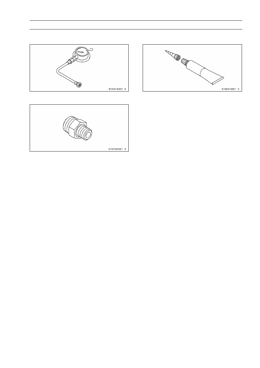
Special Tools and Sealant

Oil Pressure Gauge, 10 kgf/cm²:
57001-164

Oil Pressure Gauge Adapter, PT3/8:
57001-1233

Kawasaki Bond (Silicone Sealant):
56019-120

7-8 ENGINE LUBRICATION SYSTEM

Engine Oil and Oil Filter

WARNING

Motorcycle operation with insufficient,

deteri-

orated, or contaminated engine oil will cause
accelerated wear and may result in engine or trans-
mission seizure, accident, and injury.

Oil Level Inspection

Check that the engine oil level is between the upper [A]
and lower [B] levels in the gauge.

NOTE

Situate the motorcycle so that it is perpendicular to the
ground.

If the motorcycle has just been used, wait several min-
utes for all the oil to drain down.

If the oil has just been changed, start the engine and
run it for several minutes at idle speed. This fills the oil
filter with oil. Stop the engine, then wait several minutes
until the oil settles.

CAUTION

Racing the engine before the oil reaches every part
can cause engine seizure.
If the engine oil gets extremely low or if the oil pump
or oil passages clog up or otherwise do not function
properly, the oil pressure warning indicator light
(LED) will blink. If this blink stays on when the en-
gine is running above idle speed, stop the engine
immediately and find the cause.

If the oil level is too high, remove the excess oil, using a
syringe or some other suitable device.
If the oil level is too low, add the correct amount of oil
through the oil filter opening. Use the same type and
make of oil that is already in the engine.

NOTE

If the engine oil type and make are unknown, use any
brand of the specified oil to top off the level in preference
to running the engine with the oil level low. Then at your
earliest convenience, change the oil completely.

Engine Oil Change

Refer to the Engine Oil Change in the Periodic Mainte-
nance chapter.

Oil Filter Replacement

Refer to the Oil Filter Replacement in the Periodic Main-
tenance chapter.

ENGINE LUBRICATION SYSTEM 7-9

Oil Pan

Oil Pan Removal

Drain the engine oil (see Engine Oil Change in the Peri-
odic Maintenance chapter).

Remove:

Lower Fairing Brackets (see Lower Fairing Bracket Re-
moval in the Frame chapter)
Exhaust Pipe (see Exhaust Pipe Removal in the Engine
Top End chapter)
Muffler Body (see Muffler Body Removal in the Engine
Top End chapter)

Remove:

Oil Pan Bolts [A]
Oil Pan [B]

Remove the following from the oil pan as necessary.

Filter Plate Bolts [A]
Filter Plate [B]
Filter [C]

Remove the following from the lower crankcase half as
necessary.

Oil Screen [A]
Oil Pipe Plate Bolt [B]
Oil Pipe Plate [C]
Oil Pipes [D]
Dampers [E]

7-10 ENGINE LUBRICATION SYSTEM

Oil Pan

Oil Pan Installation

Replace the O-rings with new ones.

Apply grease to the O-rings on the oil pipes [A].

Install the oil pipe plate [B] so that its guide portion fits the
oil pipe as shown in the figure.

Apply a non-permanent locking agent to the oil pipe plate
bolt.

Torque - Oil Pipe Plate Bolt [C]: 9.8 N·m (1.0 kgf·m, 87 in·lb)

Install the damper [D] to the end of the breather pipe.

Apply grease to the damper.

Apply grease to the damper [A] on the oil screen [B], and
install it on the lower crankcase half as shown in the fig-
ure.

Install the oil screen so that its guide portion [C] fits the
crankcase rib [D].

Apply non-permanent locking agent to the filter plate bolts
and tighten them.

Torque - Filter Plate Bolts: 9.8 N·m (1.0 kgf·m, 87 in·lb)

Replace the oil pan gasket with a new one.

When installing the oil pan, align [A] the damper [B] on
the breather pipe with the hollow [C] of the oil pan.

Tighten the oil pan bolts following the specified tightening
sequence.

Torque - Oil Pan Bolts: 12 N·m (1.2 kgf·m, 106 in·lb)

ENGINE LUBRICATION SYSTEM 7-11

Oil Pressure Relief Valve

Oil Pressure Relief Valve Removal

Remove:

Oil Pan (see Oil Pan Removal)
Oil Pressure Relief Valve [A]

Oil Pressure Relief Valve Installation

Apply a non-permanent locking agent to the threads of
the oil pressure relief valve, and tighten it.

CAUTION

Do not apply too much non-permanent locking
agent to the threads. This may block the oil pas-
sage.

Torque - Oil Pressure Relief Valve: 15 N·m (1.5 kgf·m, 11

ft·lb)

Install the oil pan (see Oil Pan Installation).

Oil Pressure Relief Valve Inspection

Remove the oil pressure relief valve (see Oil Pressure
Relief Valve Removal).

Check to see if the valve [A] slides smoothly when push-
ing it in with a wooden or other soft rod, and see if it comes
back to its seat by spring [B] pressure.

NOTE

Inspect the valve in its assembled state. Disassembly
and assembly may change the valve performance.

If any rough spots are found during above inspection,
wash the valve clean with a high-flash point solvent and
blow out any foreign particles that may be in the valve with
compressed air.

WARNING

Clean the oil pressure relief valve in a well
-ventilated area, and take care that there is no
spark or flame anywhere near the working area.
Because of the danger of highly flammable liquids,
do not use gasoline or low-flash point solvent.

If cleaning does not solve the problem, replace the oil
pressure relief valve as an assembly. The oil pressure
relief valve is precision made with no allowance for re-
placement of individual parts.

7-12 ENGINE LUBRICATION SYSTEM

Oil Pump

Oil Pump Removal

Remove:

Clutch (see Clutch Removal in the Clutch chapter)
Oil Pump Cover Bolts [A]

Temporarily install the oil pump sprocket bolt [A].

NOTE

The oil pump sprocket bolt has a left-hand threads.

Using the oil pump sprocket bolt [A], pull out the oil pump
[B] as an assembly.

Remove the outer rotor [A] for feed pump.

Remove the oil pump cover [A].

ENGINE LUBRICATION SYSTEM 7-13

Oil Pump

Remove:

Inner Rotor [A] for Scavenge Pump
Outer Rotor [B] for Scavenge Pump

Remove the pin [A].

Remove:

Pin [A]
Inner Rotor for Feed Pump [B]
Oil Pump Shaft [C]

Oil Pump Installation

Apply molybdenum disulfide oil solution to the portion [A]
of the oil pump shaft as shown in the figure.

Assemble the following parts.

Oil Pump Shaft [B]
Pin [C]
Inner Rotor for Feed Pump [D]
Oil Pump Body [E]
Pin [F]
Inner Rotor [G] for Scavenge Pump
Outer Rotor [H] for Scavenge Pump

NOTE

The scavenge pump rotors are wider than the feed
pump rotors.

7-14 ENGINE LUBRICATION SYSTEM

Oil Pump

Install:

Dowel Pin [A]
Outer Rotor [B] for Feed Pump

Fit the pin of the crankcase into the hole [C] in the oil pump
body.

Turn the oil pump shaft so that the inner rotor [D] fits into
the outer rotor.

Fit the pin [A] into the hole [B] on the oil pump cover [C].

Apply a non-permanent locking agent to the oil pump
cover bolts and tighten them.

Torque - Oil Pump Cover Bolts: 9.8 N·m (1.0 kgf·m, 87 in·lb)

Check whether the oil pump turns smoothly.

ENGINE LUBRICATION SYSTEM 7-15

Oil Pressure Measurement

Oil Pressure Measurement

Remove:

Right Lower Fairing Bracket (see Lower Fairing Bracket
Removal in the Frame chapter)
Oil Passage Plug [A]

Attach the adapter [A] and gauge [B] to the plug hole.

Special Tools - Oil Pressure Gauge, 10 kgf/cm²: 57001-164

Oil Pressure Gauge Adapter, PT3/8: 57001

-1233

Start the engine and warm up the engine.

Run the engine at the specified speed, and read the oil
pressure gauge.
If the oil pressure is much lower than the standard, check
the oil pump, relief valve, and/or crankshaft bearing insert
wear immediately.
If the reading is much higher than the standard, check the
oil passages for clogging.

Oil Pressure

Standard:

216

294 kPa (2.2

3.0 kgf/cm², 31

43

psi) at 4 000 r/min (rpm), oil temperature
90°C (194°F)

Stop the engine.

Remove the oil pressure gauge and adapter.

WARNING

Take care against burns form hot engine oil that
will drain through the oil passage when the gauge
adapter is removed.

Apply a non-permanent locking agent to the oil passage
plug, and install it.

Torque - Oil Passage Plug: 20 N·m (2.0 kgf·m, 15 ft·lb)

7-16 ENGINE LUBRICATION SYSTEM

Oil Pressure Switch

Oil Pressure Switch Removal

Drain the engine oil (see Engine Oil Change in the Peri-
odic Maintenance chapter).

Remove:

Lower Fairing (see Lower Fairing Removal in the Frame
chapter)
Switch Cover [A]
Switch Terminal Bolt [B]
Oil Pressure Switch [C]

Oil Pressure Switch Installation

Apply silicone sealant to the threads of the oil pressure
switch [A] and tighten it.

Sealant - Kawasaki Bond (Silicone Sealant): 56019-120

Torque - Oil Pressure Switch: 15 N·m (1.5 kgf·m, 11 ft·lb)

Install the switch lead [B] direction downward.

Apply grease to the terminal [C], and tighten the terminal
bolt securely.

Front [D]

NOTE

Apply a small amount grease to the terminal so that
grease should not close two breather holes [A] for
switch diaphragm.

ENGINE REMOVAL/INSTALLATION 8-1

8

Engine Removal/Installation

Table of Contents

Exploded View........................................................................................................................

8-2

Engine Removal/Installation ...................................................................................................

8-4

Engine Removal................................................................................................................

8-4

Engine Installation.............................................................................................................

8-6

8-2 ENGINE REMOVAL/INSTALLATION

Exploded View

ENGINE REMOVAL/INSTALLATION 8-3

Exploded View

Torque

No.

Fastener

N·m

kgf·m

ft·lb

Remarks

1

Engine Mounting Nut (Lower)

44

4.5

32

S

2

Engine Mounting Nut (Rear)

44

4.5

32

S

3

Engine Bracket Bolts (Left)

25

2.5

18

S

4

Engine Mounting Bolt (Left)

44

4.5

32

S

5

Engine Bracket Bolts (Right)

25

2.5

18

S

6

Engine Mounting Bolt (Right)

44

4.5

32

S

S: Follow the specified tightening sequence.

8-4 ENGINE REMOVAL/INSTALLATION

Engine Removal/Installation

Engine Removal

Support the rear part of the swingarm with a stand.

Squeeze the brake lever slowly and hold it with a band
[A].

WARNING

Be sure to hold the front brake when removing the
engine, or the motorcycle may fall over. It could
cause an accident and injury.

CAUTION

Be sure to hold the front brake when removing the
engine, or the motorcycle may fall over. The engine
or the motorcycle could be damaged.

Drain:

Engine Oil (see Engine Oil Change in the Periodic Main-
tenance chapter)
Coolant (see Coolant Change in the Periodic Mainte-
nance chapter)

Remove:

Air Switching Valve and Hose (see Air Switching Valve
Removal in the Engine Top End chapter)
Throttle Body Assy (see Throttle Body Assy Removal in
the Fuel System (DFI) chapter)
Radiator and Water Hoses (see Radiator and Radiator
Fan Removal in the Cooling System chapter)
Frame Covers (see Frame Cover Removal in the Frame
chapter)
Lower Fairing Brackets (see Lower Fairing Bracket Re-
moval in the Frame chapter)
Exhaust Pipe (see Exhaust Pipe Removal in the Engine
Top End chapter)
Muffler Body (see Muffler Body Removal in the Engine
Top End chapter)
Clutch Cable (see Clutch Cable Removal in the Clutch
chapter)
Stick Coils (see Stick Coil Removal in the Electrical Sys-
tem chapter)
Shift Pedal (see Shift Pedal Removal in the Crank-
shaft/Transmission chapter)
Engine Sprocket (see Engine Sprocket Removal in the
Final Drive chapter)

ENGINE REMOVAL/INSTALLATION 8-5

Engine Removal/Installation

Remove the baffle plate bolts [A], and take off the baffle
plate [B].

Slide out the rubber cap [A].

Disconnect the oil pressure switch lead terminal [B].

Disconnect:

Crankshaft Sensor Lead Connector [A]
Starter Motor Cable Terminal [B]
Engine Ground Lead Terminal [C]

Disconnect:

Alternator Lead Connector [A]
Sidestand Switch Lead Connector [B]
Speed Sensor Lead Connector [C]
Water Temperature Sensor Lead Connector [D]

Disconnect the neutral switch lead terminal [A].

8-6 ENGINE REMOVAL/INSTALLATION

Engine Removal/Installation

Support the engine using a suitable stand or jack [A].

Put planks [B] to balance the engine.

Remove the engine mounting bolt [A] on both sides.

Remove the bracket bolts [B] on both sides.

Remove the engine mounting bolts [C], and take off the
engine.

Engine Installation

Support the engine using a suitable stand or jack.

Put planks to balance the engine.

Install the dampers [A].

Install the engine to the frame.

Insert the lower and rear engine mounting bolts.

Install the left engine bracket [A] temporary.

Install the right engine bracket [B] temporary.

Place the collar [C] as shown in the figure.

ENGINE REMOVAL/INSTALLATION 8-7

Engine Removal/Installation

By the following specified sequence, tighten the engine
mounting bolts and nuts.

Tighten:

Torque - Engine Mounting Nut (Lower) [A]: 44 N·m (4.5

kgf·m, 32 ft·lb)

Tighten:

Torque - Engine Mounting Nut (Rear) [B]: 44 N·m (4.5 kgf·m,

32 ft·lb)

Tighten:

Torque - Engine Bracket Bolts (Left) [C]: 25 N·m (2.5 kgf·m,

18 ft·lb)

Tighten:

Torque - Engine Mounting Bolt (Left) [D]: 44 N·m (4.5 kgf·m,

32 ft·lb)

Tighten:

Torque - Engine Bracket Bolts (Right) [E]: 25 N·m (2.5

kgf·m, 18 ft·lb)

Tighten:

Torque - Engine Mounting Bolt (Right) [F]: 44 N·m (4.5

kgf·m, 32 ft·lb)

8-8 ENGINE REMOVAL/INSTALLATION

Engine Removal/Installation

Run the leads, cables, and hoses correctly (see Cable,
Wire, and Hose Routing section in the Appendix chapter).

Tighten:

Torque - Engine Ground Lead Terminal Bolt: 9.8 N·m (1.0

kgf·m, 87 in·lb)

Install the removed parts (see appropriate chapters).

Adjust:

Throttle Cables (see Throttle Control System Inspection
in the Periodic Maintenance chapter)
Clutch Cable (see Clutch Operation Inspection in the Pe-
riodic Maintenance chapter)
Drive Chain (see Drive Chain Slack Adjustment in the
Periodic Maintenance chapter)

Fill the engine with engine oil (see Engine Oil Change in
the Periodic Maintenance chapter).

Fill the engine with coolant and bleed the air from the cool-
ing system (see Coolant Change in the Periodic Mainte-
nance chapter).

Adjust the idling (see Idle Speed Adjustment in the Peri-
odic Maintenance chapter).

CRANKSHAFT/TRANSMISSION 9-1

9

Crankshaft/Transmission

Table of Contents

Exploded View........................................................................................................................

9-2

Specifications .........................................................................................................................

9-6

Special Tools and Sealants ....................................................................................................

9-9

Crankcase Splitting.................................................................................................................

9-10

Crankcase Splitting ...........................................................................................................

9-10

Crankcase Assembly ........................................................................................................

9-12

Crankshaft and Connecting Rods...........................................................................................

9-18

Crankshaft Removal .........................................................................................................

9-18

Crankshaft Installation ......................................................................................................

9-18

Connecting Rod Removal .................................................................................................

9-18

Connecting Rod Installation ..............................................................................................

9-19

Crankshaft/Connecting Rod Cleaning...............................................................................

9-22

Connecting Rod Bend.......................................................................................................

9-22

Connecting Rod Twist .......................................................................................................

9-23

Connecting Rod Big End Side Clearance .........................................................................

9-23

Connecting Rod Big End Bearing Insert/Crankpin Wear ..................................................

9-23

Crankshaft Side Clearance ...............................................................................................

9-25

Crankshaft Runout ............................................................................................................

9-25

Crankshaft Main Bearing Insert/Journal Wear ..................................................................

9-26

Balancer .................................................................................................................................

9-28

Balancer Removal.............................................................................................................

9-28

Balancer Installation..........................................................................................................

9-28

Balancer Shaft Bearing Insert/Journal Clearance.............................................................

9-28

External Shift Mechanism.......................................................................................................

9-31

Shift Pedal Removal .........................................................................................................

9-31

Shift Pedal Installation ......................................................................................................

9-31

External Shift Mechanism Removal ..................................................................................

9-31

External Shift Mechanism Installation ...............................................................................

9-32

External Shift Mechanism Inspection................................................................................

9-33

Transmission ..........................................................................................................................

9-34

Transmission Assy Removal.............................................................................................

9-34

Transmission Assy Installation..........................................................................................

9-34

Transmission Assy Disassembly ......................................................................................

9-35

Transmission Assy Assembly ...........................................................................................

9-36

Transmission Shaft Removal ............................................................................................

9-37

Transmission Shaft Installation .........................................................................................

9-37

Transmission Shaft Disassembly ......................................................................................

9-38

Transmission Shaft Assembly...........................................................................................

9-38

Shift Drum and Fork Removal...........................................................................................

9-41

Shift Drum and Fork Installation........................................................................................

9-41

Shift Drum Disassembly....................................................................................................

9-41

Shift Drum Assembly ........................................................................................................

9-41

Shift Fork Bending ............................................................................................................

9-41

Shift Fork/Gear Groove Wear ...........................................................................................

9-41

Shift Fork Guide Pin/Drum Groove Wear..........................................................................

9-41

Gear Dog and Gear Dog Hole Damage............................................................................

9-42

Ball Bearing, Needle Bearing, and Oil Seal............................................................................

9-43

Ball and Needle Bearing Replacement .............................................................................

9-43

Ball and Needle Bearing Wear..........................................................................................

9-43

Oil Seal Inspection ............................................................................................................

9-43

9-2 CRANKSHAFT/TRANSMISSION

Exploded View

CRANKSHAFT/TRANSMISSION 9-3

Exploded View

Torque

No.

Fastener

N·m

kgf·m

ft·lb

Remarks

1

Connecting Rod Big End Nuts

see Text

MO

2

Timing Rotor Bolt

40

4.1

30

3

Oil Plate Bolts

9.8

1.0

87 in·lb

L

4

Oil Pipe Bolts

9.8

1.0

87 in·lb

L

5

Breather Plate Bolts

9.8

1.0

87 in·lb

L

6

Shift Shaft Return Spring Pin

29

3.0

21

L

7

Crankcase Bolt (M6, L = 32 mm)

19.6

2.0

14

S

8

Crankcase Bolts (M6, L = 38 mm)

19.6

2.0

14

S

9

Crankcase Bolts (M6, L = 45 mm)

19.6

2.0

14

S

10

Crankcase Bolt (M8, L = 50 mm)

27.5

2.8

20

S

11

Crankcase Bolts (M8, L = 60 mm)

35

3.6

26

MO, S

12

Crankcase Bolts (M8, L = 73 mm)

35

3.6

26

MO, S

13

Crankcase Bolt (M8, L = 110 mm)

27.5

2.8

20

S

14

Crankcase Bolts (M9, L = 83 mm)

44

4.5

32

MO, S

15

Crankcase Bolts (M9, L = 113 mm)

44

4.5

32

MO, S

16

Crankcase Bolt (M8, L = 60 mm)

27.5

2.8

20

S

17

Upper Crankcase Bolts (M8, L = 110 mm)

27.5

2.8

20

S

18

Upper Crankcase Bolt (M8, L = 120 mm)

27.5

2.8

20

S

G: Apply grease.

HG: Apply high-temperature grease.

L: Apply a non-permanent locking agent.

LG: Apply liquid gasket.

MO: Apply molybdenum disulfide oil solution.

(mixture of the engine oil and molybdenum disulfide grease in a weight ratio 10 : 1)

R: Replacement Parts

S: Follow the specified tightening sequence.

SS: Apply silicone sealant.

9-4 CRANKSHAFT/TRANSMISSION

Exploded View

CRANKSHAFT/TRANSMISSION 9-5

Exploded View

Torque

No.

Fastener

N·m

kgf·m

ft·lb

Remarks

1

Transmission Case Bolts

20

2.0

15

2

Gear Positioning Lever Bolt

12

1.2

106 in·lb

L

3

Trasnmission Case Oil Nozzle

2.9

0.30

26 in·lb

L

4

Shift Drum Cam Bolt

12

1.2

106 in·lb

L

5

Shift Drum Bearing Holder Screws

4.9

0.50

43 in·lb

L

6

Shift Rod Plate Bolt

9.8

1.0

87 in·lb

L

7

Neutral Switch Holder Screw

4.9

0.50

43 in·lb

L

8

Race Holder Screw

4.9

0.50

43 in·lb

L

9

Drive Shaft Bearing Holder Screw

4.9

0.50

43 in·lb

L

10

Shift Shaft Cover Bolts

9.8

1.0

87 in·lb

L (3)

11

Shift Shaft Cover Screw

4.9

0.50

43 in·lb

L, S

12

Neutral Switch

15

1.5

11

13

Shift Pedal Bolt

12

1.2

106 in·lb

EO: Apply engine oil.

G: Apply grease.

L: Apply a non-permanent locking agent.

MO: Apply molybdenum disulfide oil solution.

(mixture of the engine oil and molybdenum disulfide grease in a weight ratio 10 : 1)

R: Replacement Parts

9-6 CRANKSHAFT/TRANSMISSION

Specifications

Item

Standard

Service Limit

Crankshaft, Connecting Rods

Connecting Rod Bend

– – –

TIR 0.2/100 mm

(0.008/3.94 in.)

Connecting Rod Twist

– – –

TIR 0.2/100 mm

(0.008/3.94 in.)

Connecting Rod Big End Side Clearance

0.13

0.38 mm

(0.0051

0.0150 in.)

0.58 mm

(0.023 in.)

Connecting Rod Big End Bearing Insert/Crankpin
Clearance

0.017

0.041 mm

(0.0007

0.0016 in.)

0.08 mm

(0.003 in.)

Crankpin Diameter:

37.984

38.000 mm

(1.4954

1.4961 in.)

37.97 mm

(1.4949 in.)

Marking:

None

37.984

37.992 mm

(1.4954

1.4957 in.)

– – –

37.993

38.000 mm

(1.4958

1.4961 in.)

– – –

Connecting Rod Big End Inside Diameter:

41.000

41.016 mm

(1.6142

1.6148 in.)

– – –

Marking:

None

41.000

41.008 mm

(1.6142

1.6145 in.)

– – –

41.009

41.016 mm

(1.6145

1.6148 in.)

– – –

Connecting Rod Big End Bearing Insert Thickness:

Brown

1.475

1.480 mm

(0.05807

0.05827 in.)

– – –

Black

1.480

1.485 mm

(0.05827

0.05846 in.)

– – –

Blue

1.485

1.490 mm

(0.05846

0.05866 in.)

– – –

Connecting Rod Big End Bearing Insert Selection:

Bearing Insert

Connecting Rod

Big End Inside

Diameter Marking

Crankpin Diameter

Marking

Size Color

Part Number

None

Brown

92139-0116

None

None

Black

92139-0115

None

Blue

92139-0114

Connecting Rod Bolt Stretch:

(Usable Range)

New Connecting Rod

0.24

0.36 mm

(0.0094

0.0142 in.)

– – –

Used Connecting Rod

0.20

0.32 mm

(0.0079

0.0126 in.)

– – –

Crankshaft Side Clearance

0.05

0.20 mm

(0.0020

0.0079 in.)

0.40 mm

(0.016 in.)

CRANKSHAFT/TRANSMISSION 9-7

Specifications

Item

Standard

Service Limit

Crankshaft Runout

TIR 0.02 mm (0.0008 in.)
or less

TIR 0.05 mm

(0.002 in.)

Crankshaft Main Bearing Insert/Journal Clearance

0.012

0.036 mm

(0.0005

0.0014 in.)

0.07 mm

(0.003 in.)

Crankshaft Main Journal Diameter:

37.984

38.000 mm

(1.4954

1.4961 in.)

37.96 mm

(1.4945 in.)

Marking:

None

37.984

37.992 mm

(1.4954

1.4957 in.)

– – –

1

37.993

38.000 mm

(1.4958

1.4961 in.)

– – –

Crankcase Main Bearing Inside Diameter:

41.000

41.016 mm

(1.6142

1.6148 in.)

– – –

Marking:

41.000

41.008 mm

(1.6142

1.6145 in.)

– – –

None

41.009

41.016 mm

(1.6145

1.6148 in.)

– – –

Crankshaft Main Bearing Insert Thickness:

Brown

1.490

1.494 mm

(0.05866

0.05882 in.)

– – –

Black

1.494

1.498 mm

(0.05882

0.05898 in.)

– – –

Blue

1.498

1.502 mm

(0.05898

0.05913 in.)

– – –

Crankshaft Main Bearing Insert Selection:

Bearing Insert*

Crankcase Main

Bearing Inside

Diameter Marking

Crankshaft Main

Journal Diameter

Marking

Size Color

Part Number

1

Brown

92028-1905

None

1

None

Black

92028-1904

None

None

Blue

92028-1903

*The bearing inserts for Nos. 1, 2 and 3 journals have oil grooves.

Balancer Shaft

Balancer Shaft Bearing Insert/Journal Clearance

0.011

0.033 mm

(0.0004

0.0013 in.)

0.08 mm

(0.003 in.)

Balancer Shaft Journal Diameter:

27.987

28.000 mm

(1.1019

1.1024 in.)

27.96 mm

(1.1008 in.)

Marking:

None

27.987

27.993 mm

(1.1019

1.1021 in.)

– – –

27.994

28.000 mm

(1.1021

1.1024 in.)

– – –

9-8 CRANKSHAFT/TRANSMISSION

Specifications

Item

Standard

Service Limit

Crankcase Bearing Bore Diameter:

31.000

31.016 mm

(1.2205

1.2211 in.)

– – –

Marking:

31.000

31.008 mm

(1.2205

1.2208 in.)

– – –

None

31.009

31.016 mm

(1.2208

1.2211 in.)

– – –

Balancer Shaft Bearing Insert Thickness:

Brown

1.490

1.494 mm

(0.05866

0.05882 in.)

– – –

Black

1.494

1.498 mm

(0.05882

0.05898 in.)

– – –

Blue

1.498

1.502 mm

(0.05898

0.05913 in.)

– – –

Balancer Shaft Bearing Insert Selection:

Bearing Insert*

Crankcase Bearing

Inside Diameter

Marking

Balancer Shaft

Journal Diameter

Marking

Size Color

Part Number

Brown

92139-0119

None

None

Black

92139-0118

None

None

Blue

92139-0117

*The bearing inserts for Nos. 1 and 2 journals have oil grooves.

Transmission

Shift Fork Ear Thickness

5.9

6.0 mm

(0.232

0.236 in.)

5.8 mm

(0.23 in.)

Gear Groove Width

6.05

6.15 mm

(0.238

0.242 in.)

6.3 mm

(0.25 in.)

Shift Fork Guide Pin Diameter

6.9

7.0 mm

(0.272

0.276 in.)

6.8 mm

(0.27 in.)

Shift Drum Groove Width

7.05

7.20 mm

(0.278

0.283 in.)

7.3 mm

(0.29 in.)

CRANKSHAFT/TRANSMISSION 9-9

Special Tools and Sealants

Outside Circlip Pliers:
57001-144

Bearing Driver Set:
57001-1129

Kawasaki Bond (Silicone Sealant):
92104-0004

Kawasaki Bond (Liquid Gasket - Black):
92104-1064

9-10 CRANKSHAFT/TRANSMISSION

Crankcase Splitting

Crankcase Splitting

Remove the engine (see Engine Removal in the Engine
Removal/Installation chapter)

Set the engine on a clean surface and hold the engine
steady while parts are being removed.

Remove:

Pistons (see Piston Removal in the Engine Top End
chapter)
Alternator Rotor (see Alternator Rotor Removal in the
Electrical System chapter)
Starter Motor (see Starter Motor Removal in the Electri-
cal System chapter)
Timing Rotor (see Timing Rotor Removal in the Electrical
System chapter)
Clutch (see Clutch Removal in the Clutch chapter)
Oil Pump (see Oil Pump Removal in the Engine Lubri-
cation System chapter)
Water Pump (see Water Pump Removal in the Cooling
System chapter)
Transmission Assy (see Transmission Assy Removal)

Remove the upper crankcase bolts [A] and the washers.

CRANKSHAFT/TRANSMISSION 9-11

Crankcase Splitting

Remove the oil pan, oil screen and oil pipes (see Oil Pan
Removal in the Engine Lubrication System chapter).

Remove the lower crankcase bolts, following the specified
sequence.

Firstly, loosen the M6 bolts [A].

Secondly, loosen the M8 bolts [B].

Lastly, loosen the M9 bolts [C].

Tap lightly around the crankcase mating surface with a
plastic mallet, and split the crankcase. Take care not to
damage the crankcase.

If the oil pipe is to be removed, follow the next procedure.

Unscrew the bolts [A] and remove the oil pipe [B].

Prepare a

5 mm rod [A], and insert it to the hole of the

upper crankcase half.

Remove the oil pipe [B], tapping [C] the rod as shown.

If the breather plate [A] is to be removed, follow the next
procedure.

Remove the oil pipe (see above).

Cut the gasket around the plate [B].

Remove:

Breather Plate Bolts [C]
Breather Plate with Pipe [D]

9-12 CRANKSHAFT/TRANSMISSION

Crankcase Splitting

Crankcase Assembly

CAUTION

The upper and lower crankcase halves are ma-
chined at the factory in the assembled state, so the
crankcase halves must be replaced as a set.

With a high-flash point solvent, clean off the mating sur-
faces of the crankcases halves and wipe dry.

Using compressed air, blow out the oil passages in the
crankcase halves.

If the oil plate [A] on the upper crankcase half was re-
moved, install it as shown.

Apply a non-permanent locking agent to the oil plate bolts
and tighten them.

Torque - Oil Plate Bolts [B]: 9.8 N·m (1.0 N·m, 87 in·lb)

When the new needle bearing [A] for the shift drum is
installed in the lower crankcase half [B], press and insert
[C] the new needle bearing until it is bottomed.

Special Tool - Bearing Driver Set: 57001-1129

When the new needle bearing [D] for the shift shaft is
installed in the lower crankcase half, press and insert [E]
the new needle bearing so that the bearing surface is flush
with the end of hole.

The marked side of the needle bearing faces outside of
the crankcase.

Special Tool - Bearing Driver Set: 57001-1129

When the new oil plug [A] and new race [B] for drive shaft
is installed in the upper crankcase half [C], install them
using the following steps.

Apply grease to the new O-rings [D].

Apply silicone sealant to the portions [E] on the upper
crankcase half, and insert [F] the new oil plug until it is
bottomed.

Sealant - Kawasaki Bond (Silicone Sealant): 92104-0004

Press and insert the new race until it is bottomed.

Special Tool - Bearing Driver Set: 57001-1129

NOTE

Install the new race so that the stepped side [G] faces
inside of the crankcase.

Do not apply silicone sealant to the O-ring and the oil
line.

Install the race holder [H] direction as shown.

Apply a non-permanent locking agent to the threads of
the race holder screw [I] and tighten it.

Torque - Race Holder Screw: 4.9 N·m (0.50 kgf·m, 43 in·lb)

CRANKSHAFT/TRANSMISSION 9-13

Crankcase Splitting

Apply silicone sealant to the breather plate mating surface
[A] 1 mm (0.04 in.) or more thick, and then install the
breather plate.

Sealant - Three Bond: TB1207B

NOTE

Make the application finish within 7 minutes when the
liquid gasket to the mating surface of the breather plate
is applied.

Moreover fit the plate and tighten the bolts just after
application of the liquid gasket.

Apply a non-permanent locking agent to the threads and
tighten the bolts [A].

Torque - Breather Plate Bolts: 9.8 N·m (1.0 kgf·m, 87 in·lb)

Install the breather pipe [A].

Align the white mark [B] on the pipe with the white mark
[C] on the breather fitting.

Install the clamps [D] so that the pinch heads [E] face the
white marks.

Apply molybdenum disulfide oil solution to the edge of the
oil pipe [E].

Install the oil pipe [A] so that its flange [B] touches to the
surface [C] of the upper crankcase half.

Apply grease to the new O-ring [D] on the oil pipe.

Replace the O-rings [A] with new ones.

Apply grease to the new O-rings.

Apply a non-permanent locking agent to the threads of
the oil pipe bolts and tighten them.

Install the clamp with the upper oil pipe bolt.

Torque - Oil Pipe Bolts: 9.8 N·m (1.0 kgf·m, 87 in·lb)

9-14 CRANKSHAFT/TRANSMISSION

Crankcase Splitting

Install the crankshaft and the balancer shaft on the upper
crankcase half.

Apply molybdenum disulfide oil solution to the following
items.

Crankshaft Main Bearing Insert
Balancer Shaft Bearing Insert

Align [A] the timing mark on the balancer gear [B] with the
timing mark on the balancer drive gear [C] of the crank-
shaft.

Be sure to hang the camshaft chain [A] on the crankshaft.

Be sure that the dowel pins [A] are in position.

Set the bearing groove [A] on the positioning ring [B] as
shown.


Content      ..     7      8      9      10     ..