Kawasaki Ninja 650R, ER-6f, ER-6f ABS Motorcycle. Service Manual (2009-2011 year) - page 8


  Index      Manuals     Kawasaki Ninja 650R, ER-6f, ER-6f ABS Motorcycle. Service Manual (2009-2011 year)


Search            copyright infringement  


Content      ..     6      7      8      9     ..


Kawasaki Ninja 650R, ER-6f, ER-6f ABS Motorcycle. Service Manual (2009-2011 year) - page 8


ENGINE TOP END 5-35

Valves
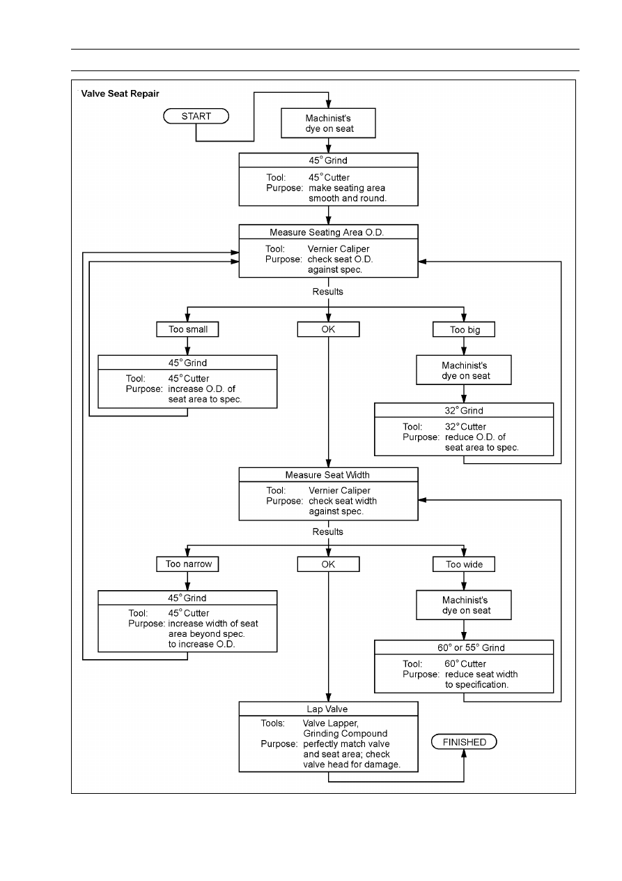
5-36 ENGINE TOP END

Cylinder, Pistons

Cylinder Removal

Remove:

Cylinder Head (see Cylinder Head Removal)
Engine Mounting Bolts (Left and Right) [A] (see Engine
Removal in the Engine Removal/Installation chapter)
Engine Brackets (Left and Right) [B] (see Engine Re-
moval in the Engine Removal/Installation chapter)
Cylinder [C]

Cylinder Installation

NOTE

If a new cylinder is used, use new piston ring.

Install the dowel pins [A] and new cylinder gasket [B].

The piston ring openings must be positioned as shown in
the figure. The openings of the oil ring steel rails must be
about 30

40° of angle from the opening of the top ring.

Top Ring [A]
Second Ring [B]
Oil Ring Steel Rails [C]
Oil Ring Expander [D]
Hollow [E]
30

40° [F]

Apply molybdenum disulfide oil solution to the cylinder
bore, piston rings and piston skirt.

Prepare two auxiliary head bolts with their head cut.

Install the two bolts [A] diagonally in the crankcase.

Position the crankshaft so that all the piston heads are
almost level.

Install the cylinder block.

Insert the piston rings with your thumbs.

Piston Removal

Remove the cylinder (see Cylinder Removal).

Place a clean cloth under the pistons and remove the pis-
ton pin snap ring [A] from the outside of each piston.

ENGINE TOP END 5-37

Cylinder, Pistons

Remove the piston pins.

Special Tools - Piston Pin Puller [A]: 57001-1568

Piston Pin Puller Adapter,

12 [D]: 57001

-1657

Center Bolt [B]
Shell of Piston [C]

Remove the pistons.

Carefully spread the ring opening with your thumbs and
then push up on the opposite side of the ring [A] to remove
it.

Remove the 3-piece oil ring with your thumbs in the same
manner.

Piston Installation

Apply molybdenum disulfide oil solution to the oil ring ex-
pander, install the oil ring expander [A] in the bottom pis-
ton ring groove so the ends [B] butt together.

Apply molybdenum disulfide oil solution to the oil ring steel
rails, and install the oil ring steel rails, one above the ex-
pander and one below it.

Spread the rail with your thumbs, but only enough to fit
the rail over the piston.

Release the rail into the bottom piston ring groove.

NOTE

The oil ring rails have no “top” or “bottom”.

Apply molybdenum disulfide oil solution to the top and
second rings.

Do not mix up the top and second ring.

Install the top ring [A] so that the "R" mark [B] faces up.

Install the second ring [C] so that the "RN" mark [D] faces
up.

5-38 ENGINE TOP END

Cylinder, Pistons

NOTE

If a new piston is used, use new piston ring.

Install the piston with its marking hollow [A] facing forward.

Fit a new piston pin snap ring into the side of the piston
so that the ring opening [A] does not coincide with the slit
[B] of the piston pin hole.

Apply molybdenum disulfide oil solution to the piston pins
and piston skirt.

When installing the piston pin snap ring, compress it only
enough to install it and no more.

CAUTION

Do not reuse snap rings, as removal weakens and
deforms them. They could fall out and score the
cylinder wall.

Install the cylinder (see Cylinder Installation).

Cylinder Wear Inspection

Since there is a difference in cylinder wear in different di-
rections, take a side-to-side and a front-to-back measure-
ment at each of the two locations (total of four measure-
ments) shown in the figure.
If any of the cylinder inside diameter measurements ex-
ceeds the service limit, replace the cylinder.

10 mm (0.39 in.) [A]
60 mm (2.36 in.) [B]

Cylinder Inside Diameter

Standard:

82.994

83.006 mm (3.2675

3.2679 in.)

Service Limit:

83.09 mm (3.271 in.)

Piston Wear Inspection

Measure the outside diameter [A] of each piston 18 mm
(0.7087 in.) [B] up from the bottom of the piston at a right
angle to the direction of the piston pin.
If the measurement is under service limit, replace the pis-
ton.

Piston Diameter

Standard:

82.969

82.984 mm (3.2665

3.2671 in.)

Service Limit:

82.82 mm (3.261 in.)

ENGINE TOP END 5-39

Cylinder, Pistons

Piston Ring, Piston Ring Groove Wear Inspection

Check for uneven groove wear by inspecting the ring seat-
ing.
The rings should fit perfectly parallel to groove surfaces.
If not, replace the piston and all the piston rings.

With the piston rings in their grooves, make several mea-
surements with a thickness gauge [A] to determine piston
ring/groove clearance.

Piston Ring/Groove Clearance

Top

Standard:

0.03

0.07 mm (0.001

0.003 in.)

Service Limit:

0.17 mm (0.0067 in.)

Second

Standard:

0.02

0.06 mm (0.001

0.002 in.)

Service Limit:

0.16 mm (0.0063 in.)

Piston Ring Groove Width Inspection

Measure the piston ring groove width.

Use a vernier caliper at several points around the piston.

Piston Ring Groove Width

Top [A]

Standard:

0.92

0.94 mm (0.0362

0.0370 in.)

Service Limit:

1.02 mm (0.0402 in.)

Second [B]

Standard:

1.01

1.03 mm (0.0398

0.0406 in.)

Service Limit:

1.11 mm (0.0437 in.)

If the width of any of the two grooves is wider than the
service limit at any point, replace the piston.

Piston Ring Thickness Inspection

Measure the piston ring thickness.

Use the micrometer to measure at several points around
the ring.

Piston Ring Thickness

Top [A]

Standard:

0.87

0.89 mm (0.0343

0.0350 in.)

Service Limit:

0.80 mm (0.031 in.)

Second [B]

Standard:

0.97

0.99 mm (0.0382

0.0390 in.)

Service Limit:

0.90 mm (0.035 in.)

If any of the measurements is less than the service limit
on either of the rings, replace all the rings.

NOTE

When using new rings in a used piston, check for un-
even groove wear. The rings should fit perfectly parallel
to the groove sides. If not, replace the piston.

5-40 ENGINE TOP END

Cylinder, Pistons

Piston Ring End Gap Inspection

Place the piston ring [A] inside the cylinder, using the pis-
ton to locate the ring squarely in place. Set it close to the
bottom of the cylinder, where cylinder wear is low.

Measure the gap [B] between the ends of the ring with a
thickness gauge.

Piston Ring End Gap

Top

Standard:

0.25

0.40 mm (0.0098

0.0157 in.)

Service Limit:

0.7 mm (0.028 in.)

Second

Standard:

0.40

0.55 mm (0.0157

0.0217 in.)

Service Limit:

0.9 mm (0.035 in.)

If the end gap of either ring is greater than the service
limit, replace all the rings.

ENGINE TOP END 5-41

Throttle Body Assy Holder

Throttle Body Assy Holder Removal

Remove:

Throttle Body Assy (see Throttle Body Assy Removal in
the Fuel System (DFI) chapter)
Clamps [A]
Bolts [B]
Throttle Body Assy Holders [C]

Throttle Body Assy Holder Installation

Be sure to install the new O-rings [A].

Apply grease to the new O-rings.

Tighten:

Torque - Throttle Body Assy Holder Bolts: 12 N·m (1.2

kgf·m, 106 in·lb)

Install the clamps [B] so that their projections [C] fit on the
holes of the holders.

Be sure that the clamp bolt heads [D] face outward.

Upside View [E]

5-42 ENGINE TOP END

Muffler

Muffler Body Removal

WARNING

To avoid a serious burn, do not remove the muffler
when the engine is still hot. Wait until the muffler
cool down.

Remove:

Right Footpeg Stay (see Footpeg Stay Removal in the
Frame chapter)
Lower Fairing Brackets (see Lower Fairing Bracket Re-
moval in the Frame chapter)
Oxygen Sensor Lead Connector [A] (Equipped Models)

Loosen the exhaust pipe manifold holder nuts [A].

Loosen the muffler body clamp bolt [A].

Remove the muffler body mounting bolts [B] and nut, and
pull the muffler body [C] to backward.

Exhaust Pipe Removal

Remove:

Lower Fairing (see Lower Fairing Removal in the Frame
chapter)
Exhaust Pipe Manifold Holder Nuts [A]

ENGINE TOP END 5-43

Muffler

Loosen the muffler body clamp bolt [A].

Remove the exhaust pipe to forward.

5-44 ENGINE TOP END

Muffler

Muffler Body and Exhaust Pipe Installation

Replace the exhaust pipe gaskets [A] and muffler body
gasket [B] with new ones and install them.

Install the muffler body gasket until it is bottomed so that
the chamfer side [C] feces exhaust pipe [D].

Install:

Muffler Body [E]
Exhaust Pipe

Tighten:

Torque - Exhaust Pipe Manifold Holder Nuts [F]: 17 N·m (1.7

kgf·m, 13 ft·lb)

Muffler Body Mounting Bolts (Front and Rear) [G]:

20 N·m (2.0 kgf·m, 15 ft·lb)

Install the muffler body clamp bolt [H] as shown in the
figure.

Tighten the muffler body clamp bolt.

Install the right footpeg stay (see Footpeg Stay Installation
in the Frame chapter).

For the oxygen sensor equipped Models, route its lead
correctly (see Cable, Wire, and Hose Routing section in
the Appendix chapter).

CAUTION

Do not pull strongly, twist, or bend the oxygen sen-
sor lead. This may cause the wiring open.

Thoroughly warm up the engine, wait until the engine
cools down, and retighten all the bolts and nuts.

CLUTCH 6-1

6

Clutch

Table of Contents

Exploded View........................................................................................................................

6-2

Specifications .........................................................................................................................

6-4

Special Tool and Sealant ........................................................................................................

6-5

Clutch Lever and Cable ..........................................................................................................

6-6

Clutch Lever Free Play Inspection ....................................................................................

6-6

Clutch Lever Free Play Adjustment ..................................................................................

6-6

Clutch Cable Removal ......................................................................................................

6-6

Clutch Cable Installation ...................................................................................................

6-6

Clutch Cable Lubrication...................................................................................................

6-7

Clutch Lever Installation....................................................................................................

6-7

Clutch Lever Adjustment...................................................................................................

6-7

Clutch Cover...........................................................................................................................

6-8

Clutch Cover Removal ......................................................................................................

6-8

Clutch Cover Installation ...................................................................................................

6-8

Release Shaft Removal ....................................................................................................

6-8

Release Shaft Installation .................................................................................................

6-9

Clutch Cover Disassembly................................................................................................

6-9

Clutch Cover Assembly.....................................................................................................

6-9

Clutch .....................................................................................................................................

6-11

Clutch Removal.................................................................................................................

6-11

Clutch Installation..............................................................................................................

6-12

Clutch Plate, Wear, Damage Inspection ...........................................................................

6-14

Clutch Plate Warp Inspection............................................................................................

6-14

Clutch Spring Free Length Measurement .........................................................................

6-14

Clutch Housing Finger Inspection .....................................................................................

6-15

Clutch Housing Spline Inspection .....................................................................................

6-15

6-2 CLUTCH

Exploded View

CLUTCH 6-3

Exploded View

Torque

No.

Fastener

N·m

kgf·m

ft·lb

Remarks

1

Clutch Cable Clamp Bracket Bolt

9.8

1.0

87 in·lb

2

Clutch Cable Holder Bolts

9.8

1.0

87 in·lb

L

3

Clutch Cover Bolts

9.8

1.0

87 in·lb

4

Clutch Hub Nut

130

13.3

96

R

5

Clutch Spring Bolts

9.8

1.0

87 in·lb

6

Timing Inspection Cap

3.9

0.40

35 in·lb

7

Timing Rotor Bolt Cap

4.9

0.50

43 in·lb

8

Oil Filler Plug

Hand-tighten

9

Oil Pump Chain Guide Bolts

12

1.2

106 in·lb

L (1)

10

Oil Pump Sprocket Bolt

12

1.2

106 in·lb

L, Lh

11

Clutch Lever Clamp Bolts

7.8

0.80

69 in·lb

S

CL: Apply cable lubricant.

EO: Apply engine oil.

G: Apply grease.

L: Apply a non-permanent locking agent.

Lh: Left-hand Threads

M: Apply molybdenum disulfide grease.

R: Replacement Parts

S: Follow the specified tightening sequence.

W: Apply water.

6-4 CLUTCH

Specifications

Item

Standard

Service Limit

Clutch Lever Free Play

2

3 mm (0.08

0.12 in.)

– – –

Clutch

Friction Plate Thickness

2.92

3.08 mm (0.115

0.121 in.)

2.8 mm (0.110 in.)

Friction Plate Warp

0.15 mm (0.0059 in.) or less

0.3 mm (0.012 in.)

Steel Plate Warp

0.2 mm (0.008 in.) or less

0.3 mm (0.012 in.)

Clutch Spring Free Length

33.60 mm (1.323 in.)

32.6 mm (1.28 in.)

CLUTCH 6-5

Special Tool and Sealant

Clutch Holder:
57001-1243

Kawasaki Bond (Silicone Sealant):
92104-0004

6-6 CLUTCH

Clutch Lever and Cable

Clutch Lever Free Play Inspection

Refer to the Clutch Operation Inspection in the Periodic
Maintenance chapter.

Clutch Lever Free Play Adjustment

Refer to the Clutch Operation Inspection in the Periodic
Maintenance chapter.

Clutch Cable Removal

Remove the right upper fairing cover (see Upper Fairing
Cover Removal in the Frame chapter).

Open the clamp [A].

Slide the dust cover [B] out of place.

Loosen the locknut [C], and turn the adjusting nut [D] to
give the cable plenty of play.

Screw in the adjuster.

Line up the slots [A] in the clutch lever [B] and adjuster
[C], and then free the cable from the lever.

Free the idle adjusting screw [A] from the bracket [B].

Remove the bolt [C] to take off the bracket.

Slide the dust cover [A] at the clutch cable lower end, and
pull the clutch cable out of the clutch cable holder [B].

Free the clutch inner cable tip [C] from the clutch release
lever [D].

Push the release lever toward the front of the motorcycle
and tape the release lever to the clutch cover to prevent
the release shaft from falling out.

Pull the clutch cable out of the frame.

Clutch Cable Installation

Run the clutch cable correctly (see Cable, Wire, and Hose
Routing section in the Appendix chapter).

Adjust the clutch cable (see Clutch Operation Inspection
in the Periodic Maintenance chapter).

CLUTCH 6-7

Clutch Lever and Cable

Clutch Cable Lubrication

Refer to the Chassis Parts Lubrication in the Periodic
Maintenance chapter.

Clutch Lever Installation

Install the clutch lever so that the mating surface [A] of the
clutch lever clamp is aligned with the punch mark [B].

Tighten the upper clamp bolt first, and then the lower
clamp bolt.

There will be a gap at the lower part of the clamp after
tightening.

Torque - Clutch Lever Clamp Bolts: 7.8 N·m (0.80 kgf·m, 69

in·lb)

Clutch Lever Adjustment

The adjuster has 5 positions so that the clutch lever posi-

tion can be adjusted to suit the operator’s hand.

Push the lever forward and turn the adjuster [A] to align
the number with the arrow mark [B] on the lever holder.

The distance from the grip to the lever is minimum at num-
ber 5 and maximum at number 1.

6-8 CLUTCH

Clutch Cover

Clutch Cover Removal

Drain the engine oil (see Engine Oil Change in the Peri-
odic Maintenance chapter).

Remove:

Right Frame Cover (see Frame Cover Removal in the
Frame chapter)
Lower Fairing (see Lower Fairing Removal in the Frame
chapter)
Clutch Cable Lower End [A] (see Clutch Cable Removal)
Clutch Cover Mounting Bolts [B]

Turn the release lever [A] toward the rear as shown, and
remove the clutch cover [B].

About 90° [C]

Clutch Cover Installation

Apply silicone sealant to the following areas [A].

Crankcase Halves Mating Surface
Crankshaft Sensor Lead Grommet

Sealant - Kawasaki Bond (Silicone Sealant): 92104-0004

Install the dowel pins [B].

Replace the clutch cover gasket with a new one.

Install the clutch cover.

Torque - Clutch Cover Bolts: 9.8 N·m (1.0 kgf·m, 87 in·lb)

Tighten with Bracket [A]

Release Shaft Removal

CAUTION

Do not remove the clutch release lever and shaft
assembly unless it is absolutely necessary. If re-
moved, the oil seal replacement may be required.

Remove the clutch cover (see Clutch Cover Removal).

Pull the lever and shaft assembly [A] straight out of the
clutch cover.

CLUTCH 6-9

Clutch Cover

Release Shaft Installation

Apply grease to the oil seal lips on the upper ridge of the
clutch cover.

Apply molybdenum disulfide grease to the pusher-holding
portion [A] on the release shaft.

Install the washer [B] and spring [C].

Insert the release shaft straight into the upper hole of the
clutch cover.

CAUTION

When inserting the release shaft, be careful not to
remove the spring of the oil seal.

Fit the spring ends [A] as shown in the figure.

Release Shaft [B]
Clutch Cover [C]

Clutch Cover Disassembly

Remove:

Clutch Cover (see Clutch Cover Removal)
Release Lever and Shaft Assembly (see Release Shaft
Removal)
Oil Seal [A]
Needle Bearings [B]

Remove:

Oil Level Gauge [A]
Timing Inspection Cap [B]
Timing Rotor Bolt Cap [C]
Oil Filler Plug [D]

Clutch Cover Assembly

Replace the needle bearings and oil seal with new ones.

NOTE

Install the needle bearings so that the manufacture’s
mark face out.

Install the needle bearings [A] and oil seal [B] position as
shown.

Press [C] the bearing so that the bearing surface [D] is
flush with the housing end of clutch cover [E].

6-10 CLUTCH

Clutch Cover

Apply water to the rubber of the oil gauge [A] and press
[B] it so that the ring [C] face outside.

Replace the O-rings of the following parts with new ones.

Timing Inspection Cap
Timing Rotor Bolt Cap
Oil Filler Plug

Apply grease to the new O-rings.

Tighten:

Torque - Timing Inspection Cap: 3.9 N·m (0.40 kgf·m, 35

in·lb)

Timing Rotor Bolt Cap: 4.9 N·m (0.50 kgf·m, 43

in·lb)

Oil Filler Plug: Hand-tighten

CLUTCH 6-11

Clutch

Clutch Removal

Remove:

Clutch Cover (see Clutch Cover Removal)
Clutch Spring Bolts [A]
Clutch Springs
Clutch Spring Plate [B] (with bearing)
Pusher [C]

Remove:

Friction Plates
Steel Plates

Hold the clutch hub [A] steady with the clutch holder [B],
and remove the clutch hub nut [C] and washer [D].

Special Tool - Clutch Holder: 57001-1243

Remove:

Clutch Hub [A]
Spacer [B]

Remove the oil pump sprocket bolt [A].

NOTE

The oil pump sprocket bolt has a left-hand threads.

Using the holes [B], pull out the sleeve [C].

Remove the following as a set.

Clutch Housing [D]
Oil Pump Chain [E]
Oil Pump Sprocket [F]

Remove:

Spacer [A]
Bolts [B]
Oil Pump Chain Guide [C]

6-12 CLUTCH

Clutch

Clutch Installation

Install the oil pump chain guide [A].

Apply a non-permanent locking agent to the upper chain
guide bolt [B].

Torque - Oil Pump Chain Guide Bolts: 12 N·m (1.2 kgf·m,

106 in·lb)

Install the spacer [C] onto the drive shaft.

Put the oil pump chain [A] on the clutch housing gear [B]
and the oil pump sprocket [C].

Install the following on the drive shaft as a set.

Clutch Housing [A]
Oil Pump Chain [B]
Oil Pump Sprocket [C]

Install the sleeve [D] so that the holes [E] faces outward.

Apply engine oil to the sleeve.
If you feel a catch as the sleeve installs, replace it with a
new one.

Align the hole on the oil pump sprocket with the oil pump
shaft.

Apply a non-permanent locking agent to the oil pump
sprocket bolt [F] and install the washer.

Tighten:

Torque - Oil Pump Sprocket Bolt: 12 N·m (1.2 kgf·m, 106

in·lb)

NOTE

The oil pump sprocket bolt has a left-hand threads.

Install the following parts onto the drive shaft.

Spacer [A]
Clutch Hub [B]

CLUTCH 6-13

Clutch

Install the washer so that the OUT SIDE mark [A] faces
outward.

Replace the clutch hub nut [A] with a new one.

Hold the clutch hub [B] steady with the clutch holder [C],
and tighten the clutch hub nut.

Special Tool - Clutch Holder: 57001-1243

Torque - Clutch Hub Nut: 130 N·m (13.3 kgf·m, 96 ft·lb)

Install the friction plates and steel plates, starting with a
friction plate and alternating them.

CAUTION

If new dry friction plates and steel plates are in-
stalled, apply engine oil to the surfaces of each
plate to avoid clutch plate seizure.

Install the last friction plate [A] fitting the tangs in the
grooves in the housing as shown in the figure.

Apply molybdenum disulfide grease to the pusher end [A].

Install the pusher [B] into the drive shaft direction as
shown in the figure.

6-14 CLUTCH

Clutch

Apply engine oil to the sliding surfaces of the bearing [A].

Install the spring plate [B] on the clutch hub [C].

Install the clutch springs, and tighten the clutch spring
bolts.

Torque - Clutch Spring Bolts: 9.8 N·m (1.0 kgf·m, 87 in·lb)

Install the clutch cover (see Clutch Cover Installation).

Clutch Plate, Wear, Damage Inspection

Visually inspect the friction and steel plates for signs of
seizure, overheating (discoloration), or uneven wear.

Measure the thickness of each friction plate [A] at several
points.
If any plates show signs of damage, or if they have worn
past the service limit, replace them with new ones.

Friction Plate Thickness

Standard:

2.92

3.08 mm (0.115

0.121 in.)

Service Limit: 2.8 mm (0.110 in.)

Clutch Plate Warp Inspection

Place each friction plate or steel plate on a surface plate
and measure the gap between the surface plate [A] and
each friction plate or steel plate [B] with a thickness gauge
[C]. The gap is the amount of friction or steel plate warp.
If any plate is warped over the service limit, replace it with
a new one.

Friction Plate Warp

Standard:

0.15 mm (0.0059 in.) or less

Service Limit: 0.3 mm (0.012 in.)

Steel Plate Warp

Standard:

0.2 mm (0.008 in.) or less

Service Limit: 0.3 mm (0.012 in.)

Clutch Spring Free Length Measurement

Measure the free length of the clutch springs [A].
If any spring is shorter than the service limit, it must be
replaced.

Clutch Spring Free Length

Standard:

33.60 mm (1.323 in.)

Service Limit: 32.6 mm (1.28 in.)

CLUTCH 6-15

Clutch

Clutch Housing Finger Inspection

Visually inspect the clutch housing fingers [A] where the
friction plate tangs [B] hit them.
If they are badly worn or if there are groove cuts where the
tangs hit, replace the housing. Also, replace the friction
plates if their tangs are damaged.

Clutch Housing Spline Inspection

Visually inspect where the teeth [A] on the steel plates
wear against the clutch hub splines [B].
If there are notches worn into the splines, replace the
clutch hub. Also, replace the steel plates if their teeth are
damaged.

ENGINE LUBRICATION SYSTEM 7-1

7

Engine Lubrication System

Table of Contents

Exploded View........................................................................................................................

7-2

Engine Oil Flow Chart.............................................................................................................

7-4

Specifications .........................................................................................................................

7-6

Special Tools and Sealant ......................................................................................................

7-7

Engine Oil and Oil Filter..........................................................................................................

7-8

Oil Level Inspection...........................................................................................................

7-8

Engine Oil Change............................................................................................................

7-8

Oil Filter Replacement ......................................................................................................

7-8

Oil Pan....................................................................................................................................

7-9

Oil Pan Removal ...............................................................................................................

7-9

Oil Pan Installation ............................................................................................................

7-10

Oil Pressure Relief Valve........................................................................................................

7-11

Oil Pressure Relief Valve Removal ...................................................................................

7-11

Oil Pressure Relief Valve Installation ................................................................................

7-11

Oil Pressure Relief Valve Inspection.................................................................................

7-11

Oil Pump.................................................................................................................................

7-12

Oil Pump Removal ............................................................................................................

7-12

Oil Pump Installation .........................................................................................................

7-13

Oil Pressure Measurement.....................................................................................................

7-15

Oil Pressure Measurement ...............................................................................................

7-15

Oil Pressure Switch ................................................................................................................

7-16

Oil Pressure Switch Removal ...........................................................................................

7-16

Oil Pressure Switch Installation ........................................................................................

7-16

7-2 ENGINE LUBRICATION SYSTEM

Exploded View

ENGINE LUBRICATION SYSTEM 7-3

Exploded View

Torque

No.

Fastener

N·m

kgf·m

ft·lb

Remarks

1

Oil Filter

17.5

1.8

13

EO, R

2

Holder Mounting Bolt

25

2.5

18

L

3

Oil Passage Plug (M6)

3.9

0.40

35 in·lb

4

Oil Passage Plug

20

2.0

15

L

5

Oil Pressure Switch

15

1.5

11

SS

6

Oil Plate Bolts

9.8

1.0

87 in·lb

L

7

Oil Pressure Relief Valve

15

1.5

11

L

8

Oil Pipe Plate Bolt

9.8

1.0

87 in·lb

L

9

Filter Plate Bolts

9.8

1.0

87 in·lb

L

10 Oil Pan Bolts

12

1.2

106 in·lb

S

11

Engine Oil Drain Plug

30

3.1

22

12 Lower Fairing Bracket Bolts

12

1.2

106 in·lb

L

13 Oil Pump Chain Guide Bolts

12

1.2

106 in·lb

L (1)

14 Oil Pump Cover Bolts

9.8

1.0

87 in·lb

L

15 Oil Pump Sprocket Bolt

12

1.2

106 in·lb

L, Lh

EO: Apply engine oil.

G: Apply grease.

L: Apply a non-permanent locking agent.

Lh: Left-hand Threads

MO: Apply molybdenum disulfide oil solution.

(mixture of the engine oil and molybdenum disulfide grease in a weight ratio 10 : 1)

R: Replacement Parts

S: Follow the specified tightening sequence.

SS: Apply silicone sealant.

7-4 ENGINE LUBRICATION SYSTEM

Engine Oil Flow Chart

ENGINE LUBRICATION SYSTEM 7-5

Engine Oil Flow Chart

7-6 ENGINE LUBRICATION SYSTEM

Specifications

Item

Standard

Engine Oil

Type

API SE, SF or SG

API SH, SJ, SL or SM with JASO MA, MA1 or MA2

Viscosity

SAE 10W-40

Capacity:

1.7 L (1.8 US gt) (when filter is not removed)

1.9 L (2.0 US gt) (when filter is removed)

2.4 L (2.5 US gt) (when engine is completely dry)

Level

Between upper and lower level lines

Oil Pressure Measurement

Oil Pressure

216

294 kPa (2.2

3.0 kgf/cm², 31

43 psi) at 4 000 r/min (rpm),

Oil Temperature 90°C (194°F)


Content      ..     6      7      8      9     ..