Kawasaki Ninja 650R, ER-6f, ER-6f ABS Motorcycle. Service Manual (2009-2011 year) - page 7
 

  Index      Manuals     Kawasaki Ninja 650R, ER-6f, ER-6f ABS Motorcycle. Service Manual (2009-2011 year)


Search            copyright infringement  


Content      ..     5      6      7      8     ..


Kawasaki Ninja 650R, ER-6f, ER-6f ABS Motorcycle. Service Manual (2009-2011 year) - page 7


ENGINE TOP END 5-3

Exploded View

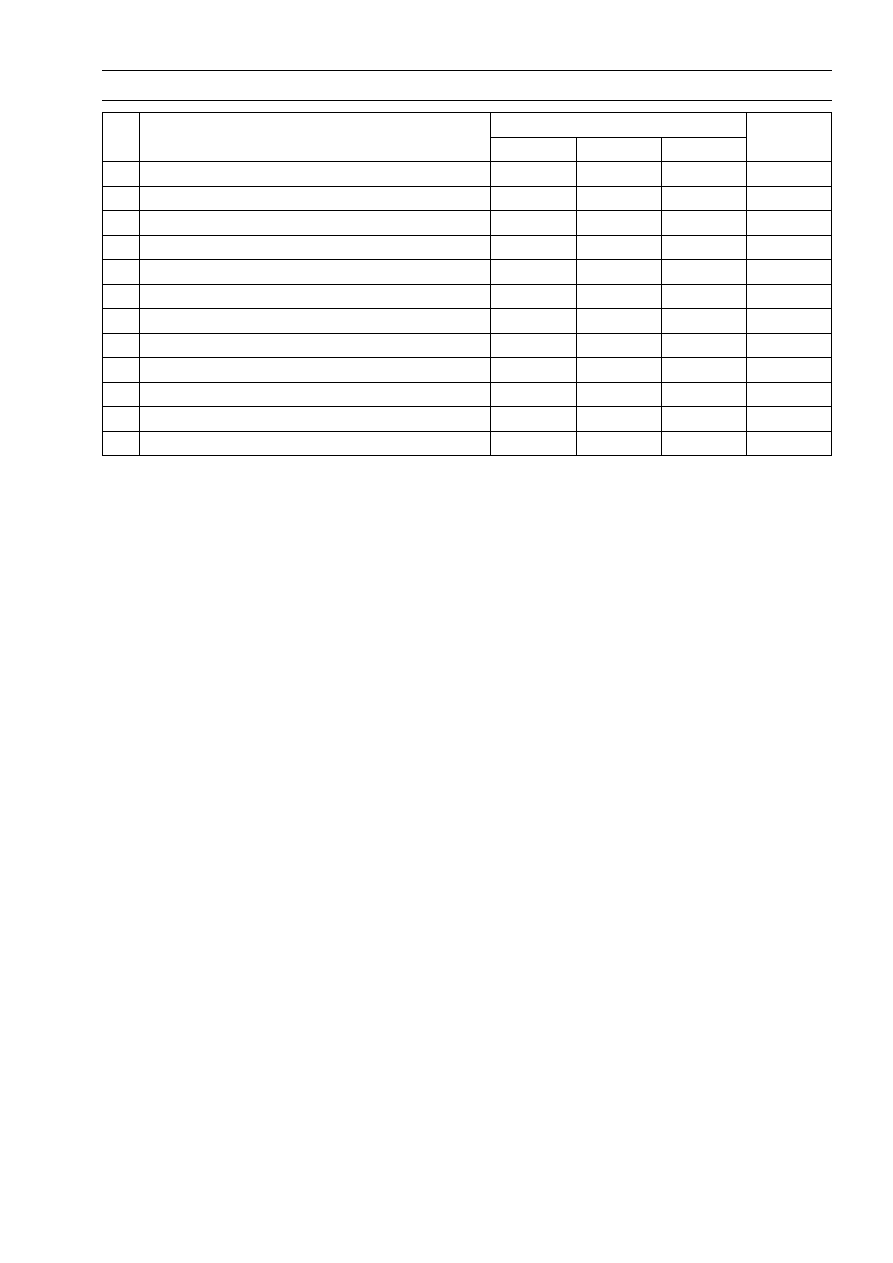
Torque

No.

Fastener

N·m

kgf·m

ft·lb

Remarks

1

Baffle Plate Bolts

5.9

0.60

52 in·lb

2

Air Suction Valve Cover Bolts

9.8

1.0

87 in·lb

3

Cylinder Head Cover Bolts

9.8

1.0

87 in·lb

4

Camshaft Cap Bolts

12

1.2

106 in·lb

S

5

Spark Plugs

15

1.5

11

6

Throttle Body Assy Holder Bolts

12

1.2

106 in·lb

7

Camshaft Sprocket Bolts

15

1.5

11

L

8

Camshaft Chain Tensioner Cap Bolt

20

2.0

15

9

Camshaft Chain Tensioner Mounting Bolts

9.8

1.0

87 in·lb

10 Rear Camshaft Chain Guide Bolt

20

2.0

15

L

11 Cylinder Head Bolts (M10)

56

5.7

41

MO, S

12 Cylinder Head Bolts (M6)

12

1.2

106 in·lb

S

EO: Apply engine oil.

G: Apply grease.

L: Apply a non-permanent locking agent.

M: Apply molybdenum disulfide grease.

MO: Apply molybdenum disulfide oil solution.

(mixture of the engine oil and molybdenum disulfide grease in a weight ratio 10 : 1)

R: Replacement Parts

S: Follow the specified tightening sequence.

SS: Apply silicone sealant.

5-4 ENGINE TOP END

Exploded View

ENGINE TOP END 5-5

Exploded View

Torque

No.

Fastener

N·m

kgf·m

ft·lb

Remarks

1

Cylinder Bolt (M8)

27.5

2.8

20

MO,S

2

Cylinder Bolts (M6)

12

1.2

106 in·lb

S

3

Cylinder Nut

49

5.0

36

MO, S

4

Exhaust Pipe Manifold Holder Nuts

17

1.7

13

5

Muffler Body Mounting Bolt (Front)

20

2.0

15

6

Muffler Body Mounting Bolt (Rear)

20

2.0

15

MO: Apply molybdenum disulfide oil solution.

(mixture of the engine oil and molybdenum disulfide grease in a weight ratio 10 : 1)

R: Replacement Parts

S: Follow the specified tightening sequence.

5-6 ENGINE TOP END

Exhaust System Identification

Exhaust System

Manifold Mark Position [A]

Muffler Body Mark Position [B]

Honeycomb Type Catalyst Position [C]

Muffler Body with Hole [D] for Oxygen Sensor [E]

ENGINE TOP END 5-7

Specifications

Item

Standard

Service Limit

Camshafts

Cam Height:

Exhaust

35.843

35.957 mm

(1.4111

1.4156 in.)

35.74 mm (1.407 in.)

Inlet

36.543

36.657 mm

(1.4387

1.4432 in.)

36.44 mm (1.435 in.)

Camshaft Journal, Camshaft
Cap Clearance

0.028

0.071 mm (0.0011

0.0028 in.)

0.16 mm (0.0063 in.)

Camshaft Journal Diameter

23.950

23.972 mm

(0.9429

0.9438 in.)

23.92 mm (0.9417 in.)

Camshaft Bearing Inside
Diameter

24.000

24.021 mm

(0.9449

0.9457 in.)

24.08 mm (0.9480 in.)

Camshaft Runout

TIR 0.02 mm (0.0008 in.) or less

TIR 0.1 mm (0.004 in.)

Cylinder Head

Cylinder Compression

(Usable Range)
1 295

1 948 kPa (13.2

19.9 kgf/cm²,

188

282 psi) at 570 r/min (rpm)

– – –

Cylinder Head Warp

– – –

0.05 mm (0.002 in.)

Valves

Valve Clearance:

Exhaust

0.22

0.31 mm (0.0087

0.0122 in.)

– – –

Inlet

0.15

0.21 mm (0.0059

0.0083 in.)

– – –

Valve Head Thickness:

Exhaust

0.8 mm (0.031 in.)

0.5 mm (0.020 in.)

Inlet

0.5 mm (0.020 in.)

0.25 mm (0.0098 in.)

Valve Stem Bend

TIR 0.01 mm (0.0004 in.) or less

TIR 0.05 mm

(0.002 in.)

Valve Stem Diameter:

Exhaust

4.455

4.470 mm (0.1754

0.1760 in.)

4.44 mm (0.175 in.)

Inlet

4.475

4.490 mm (0.1762

0.1768 in.)

4.46 mm (0.176 in.)

Valve Guide Inside Diameter:

Exhaust

4.500

4.512 mm (0.1772

0.1776 in.)

4.58 mm (0.180 in.)

Inlet

4.500

4.512 mm (0.1772

0.1776 in.)

4.58 mm (0.180 in.)

Valve/Valve Guide Clearance
(Wobble Method):

Exhaust

0.08

0.16 mm (0.0032

0.0063 in.)

0.35 mm (0.014 in.)

Inlet

0.03

0.10 mm (0.0012

0.0039 in.)

0.29 mm (0.011 in.)

Valve Seat Cutting Angle

32°, 45°, 55°, 60°

– – –

Valve Seating Surface:

Width:

Exhaust

0.5

1.0 mm (0.02

0.04 in.)

– – –

Inlet

0.5

1.0 mm (0.02

0.04 in.)

– – –

Outside Diameter:

Exhaust

27.6

27.8 mm (1.087

1.094 in.)

– – –

Inlet

32.6

32.8 mm (1.283

1.291 in.)

– – –

5-8 ENGINE TOP END

Specifications

Item

Standard

Service Limit

Valve Spring Free Length:

Exhaust

41.91 mm (1.650 in.)

40.5 mm (1.59 in.)

Inlet

41.91 mm (1.650 in.)

40.5 mm (1.59 in.)

Cylinder, Pistons

Cylinder Inside Diameter

82.994

83.006 mm

(3.2675

3.2679 in.)

83.09 mm (3.271 in.)

Piston Diameter

82.969

82.984 mm

(3.2665

3.2671 in.)

82.82 mm (3.261 in.)

Piston/Cylinder Clearance

0.010

0.037 mm (0.0004

0.0015 in.)

– – –

Piston Ring/Groove Clearance:

Top

0.03

0.07 mm (0.001

0.003 in.)

0.17 mm (0.0067 in.)

Second

0.02

0.06 mm (0.001

0.002 in.)

0.16 mm (0.0063 in.)

Piston Ring Groove Width:

Top

0.92

0.94 mm (0.0362

0.0370 in.)

1.02 mm (0.0402 in.)

Second

1.01

1.03 mm (0.0398

0.0406 in.)

1.11 mm (0.0437 in.)

Piston Ring Thickness:

Top

0.87

0.89 mm (0.0343

0.0350 in.)

0.80 mm (0.031 in.)

Second

0.97

0.99 mm (0.0382

0.0390 in.)

0.90 mm (0.035 in.)

Piston Ring End Gap:

Top

0.25

0.40 mm (0.0098

0.0157 in.)

0.7 mm (0.028 in.)

Second

0.40

0.55 mm (0.0157

0.0217 in.)

0.9 mm (0.035 in.)

ENGINE TOP END 5-9

Special Tools and Sealant

Compression Gauge, 20 kgf/cm²:
57001-221

Valve Spring Compressor Assembly:
57001-241

Valve Seat Cutter, 45° -

35:

57001-1116

Valve Seat Cutter, 32° -

30:

57001-1120

Valve Seat Cutter, 32° -

35:

57001-1121

Valve Seat Cutter, 60° -

30:

57001-1123

Valve Seat Cutter Holder Bar:
57001-1128

Valve Seat Cutter, 45° -

30:

57001-1187

Valve Seat Cutter, 55° -

35:

57001-1247

Valve Spring Compressor Adapter,

21:

57001-1272

5-10 ENGINE TOP END

Special Tools and Sealant

Compression Gauge Adapter, M10 × 1.0:
57001-1317

Valve Seat Cutter Holder,

4.5:

57001-1330

Valve Guide Arbor,

4.5:

57001-1331

Valve Guide Reamer,

4.5:

57001-1333

Piston Pin Puller:
57001-1568

Piston Pin Puller Adapter,

12:

57001-1657

Kawasaki Bond (Silicone Sealant):
92104-0004

ENGINE TOP END 5-11

Clean Air System

Air Suction Valve Removal

Remove:

Air Switching Valve (see Air Switching Valve Removal)
Air Suction Valve Cover Bolts [A]
Clamp [B]
Air Suction Valve Cover [C]

Remove the air suction valve [A].

Air Suction Valve Installation

Install the air suction valve [A] so that its side where stop-
per is fixed with the screws [B] faces the front [C].

Install the clamp [A] as shown.

Tighten:

Torque - Air Suction Valve Cover Bolts: 9.8 N·m (1.0 kgf·m,

87 in·lb)

5-12 ENGINE TOP END

Clean Air System

Air Suction Valve Inspection

Remove the air suction valve (see Air Suction Valve Re-
moval).

Visually inspect the reeds [A] for cracks, folds, warps,
heat damage or other damage.
If there is any doubt as to the condition of the reeds, re-
place the air suction valve as an assembly.

Check the reed contact areas [B] of the valve holder for
grooves, scratches, any signs of separation from the
holder or heat damage.

If there is any doubt as to the condition of the reed contact
areas, replace the air suction valve as an assembly.

If any carbon or other foreign particles have accumulated
between the reed and the reed contact area, wash the
valve assembly clean with a high-flash point solvent.

CAUTION

Do not scrape off the deposits with a scraper as this
could damage the rubber, requiring replacement of
the suction valve assembly.

Air Switching Valve Removal

Remove:

Fuel Tank (see Fuel Tank Removal in the Fuel System
(DFI) chapter)
Left Upper Fairing Cover (see Upper Fairing Cover Re-
moval in the Frame chapter)

Separate the air switching valve hose [A] from the air suc-
tion valve cover.

Disconnect the connector [A].

Separate the air switching valve hose [B] from the air
cleaner housing, and remove the air switching valve [C].

CAUTION

Never drop the air switching valve, especially on a
hard surface. Such a shock to the valve can dam-
age it.

Air Switching Valve Installation

Install the air switching valve [A] with hoses [B] as shown.

Install the clamp [C] so that its pinch heads face the right.

Connect the air switching valve lead connector.

Air Switching Valve Operation Test

Refer to the Air Suction System Damage Inspection in the
Periodic Maintenance chapter.

ENGINE TOP END 5-13

Clean Air System

Air Switching Valve Unit Test

Refer to the Air Switching Valve Unit Test in the Electrical
System chapter.

Clean Air System Hose Inspection

Be certain that all the hoses are routed without being flat-
tened or kinked, and are connected correctly to the air
cleaner housing, air switching valve and air suction valve
cover.
If they are not, correct them. Replace them if they are
damaged.

5-14 ENGINE TOP END

Cylinder Head Cover

Cylinder Head Cover Removal

Remove:

Air Suction Valve (see Air Suction Valve Removal)
Stick Coils (see Stick Coil Removal in the Electrical Sys-
tem chapter).
Throttle Cables (see Throttle Body Assy Removal in the
Fuel System (DFI) chapter)
Inlet Air Pressure Sensor Hose [A]
Baffle Plate Bolts [B]
Baffle Plate [C]
Cylinder Head Cover Bolts [D]
Clamp [E]

EX650D Models

Remove:

Upper Fairing (see Upper Fairing Removal in the Frame
chapter)
Bolt [A]
Damper [B]

Remove the cylinder head cover.

Cylinder Head Cover Installation

Replace the head cover gasket [A] with a new one.

Apply silicone sealant [B] to the cylinder head as shown
in the figure.

Sealant - Kawasaki Bond (Silicone Sealant): 92104-0004

ENGINE TOP END 5-15

Cylinder Head Cover

Replace the plug hole gaskets [A] with new ones.

Be sure to install the following parts.

Dowel Pins [B]
Plug Hole Gaskets

Install the rubber washers [A] with metal side faces up-
ward.

Tighten:

Torque - Cylinder Head Cover Bolts: 9.8 N·m (1.0 kgf·m, 87

in·lb)

Be sure that the dampers [A] of the baffle plate is in posi-
tion.

Tighten:

Torque - Baffle Plate Bolts: 5.9 N·m (0.60 kgf·m, 52 in·lb)

5-16 ENGINE TOP END

Camshaft Chain Tensioner

Camshaft Chain Tensioner Removal

CAUTION

This is a non-return type camshaft chain tensioner.
The push rod does not return to its original position
once it moves out to take up camshaft chain slack.
Observe all the rules listed below:
When removing the tensioner, do not take out the
mounting bolts only halfway.

Retightening the

mounting bolts from this position could damage
the tensioner and the camshaft chain. Once the
bolts are loosened, the tensioner must be removed
and reset as described in "Camshaft Chain Ten-
sioner Installation."
Do not turn over the crankshaft while the tensioner
is removed. This could upset the camshaft chain
timing, and damage the valves.

Remove:

Right Upper Fairing Cover (see Upper Fairing Cover Re-
moval in the Frame chapter)
Cap Bolt [A] and Washer

Remove the spring [A].

Remove the mounting bolts [B], and take off the camshaft
chain tensioner body [C].

Camshaft Chain Tensioner Installation

Replace the O-ring [A] with a new one.

Apply grease to the new O-ring.

Release the stopper [B] and push the push rod [C] into
the tensioner body [D].

ENGINE TOP END 5-17

Camshaft Chain Tensioner

Install the tensioner body so that the stopper [A] faces
upward.

Tighten the tensioner mounting bolts.

Torque - Camshaft Chain Tensioner Mounting Bolts: 9.8

N·m (1.0 kgf·m, 87 in·lb)

Install:

Spring [A]
Washer [B]

Tighten:

Torque - Camshaft Chain Tensioner Cap Bolt [C]: 20 N·m

(2.0 kgf·m, 15 ft·lb)

Turn the crankshaft 2 turns clockwise to allow the ten-
sioner to expand and recheck the camshaft chain timing.

5-18 ENGINE TOP END

Camshaft, Camshaft Chain

Camshaft Removal

Remove:

Cylinder Head Cover (see Cylinder Head Cover Re-
moval)
Lower Fairing (see Lower Fairing Removal in the Frame
chapter)
Timing Inspection Cap [A]
Timing Rotor Bolt Cap [B]

Using a wrench on the timing rotor bolt, turn the crank-
shaft clockwise until the 2/T mark line [A] on the timing
rotor is aligned with the notch [B] in the edge of the timing
inspection hole [C] in the clutch cover.

If the clutch cover is removed, perform the next proce-
dure.

Using a wrench on the timing rotor bolt, turn the crank-
shaft clockwise until the 1/T mark line [A] on the timing ro-
tor is aligned with the mating surface [B] of the crankcase
front side.

ENGINE TOP END 5-19

Camshaft, Camshaft Chain

Remove the camshaft chain tensioner (see Camshaft
Chain Tensioner Removal).

Loosen the camshaft cap bolts as shown sequence [1

12 ] in the figure, and remove them.

Remove:

Camshaft Caps [A]
Camshafts [B]

CAUTION

The crankshaft may be turned while the camshafts
are removed. Always pull the chain taut while turn-
ing the crankshaft. This avoids kinking the chain
on the lower (crankshaft) sprocket. A kinked chain
could damage both the chain and the sprocket.

Stuff a clean cloth into the chain tunnel to keep any parts
from dropping into the crankcase.

Remove the cam sprocket mounting bolts [A].

Remove the cam sprocket.

5-20 ENGINE TOP END

Camshaft, Camshaft Chain

Camshaft Installation

Replace the plug hole gaskets [A] with new ones.

Be sure to install the following parts.

Plug Hole Gaskets
Dowel Pins [B]

Install the cam sprockets so that the marked (“IN" and
“EX”) side faces to the outward.

The inlet [A] and exhaust [B] cam sprockets are identical.

CAUTION

Inlet cam sprocket must use “IN” marked bolt holes
[C]. Exhaust cam sprocket must use “EX” marked
bolt holes [D].

Apply a non-permanent locking agent to the camshaft
sprocket bolts and tighten them.

Torque - Camshaft Sprocket Bolts: 15 N·m (1.5 kgf·m, 11

ft·lb)

Apply molybdenum disulfide oil solution to all cams [A],
journals [B] and thrust blocks [C] with × marks.
If a new camshaft is to be used, apply a thin coat of molyb-
denum disulfide grease to the cam surfaces.

NOTE

The exhaust camshaft has a 2412 EX mark [D] and the
inlet camshaft has a 2412 IN mark [E]. Be careful not to
mix up these shafts.

ENGINE TOP END 5-21

Camshaft, Camshaft Chain

Using a wrench on the timing rotor bolt, turn the crank-
shaft clockwise until the 2/T mark line [A] on the timing
rotor is aligned with the notch [B] in the edge of the timing
inspection hole [C] in the clutch cover.

CAUTION

The crankshaft may be turned while the camshafts
are removed. Always pull the chain taut while turn-
ing the crankshaft. This avoids kinking the chain
on the lower (crankshaft) sprocket. A kinked chain
could damage both the chain and the sprocket.

If the clutch cover is removed, perform the next proce-
dure.

Using a wrench on the bolt, turn the crankshaft clockwise
until the 1/T mark line [A] on the timing rotor is aligned
with the mating surface [B] of the crankcase front side.

Pull the tension side (exhaust side) [A] of the chain taut
to install the chain.

Engage the camshaft chain with the camshaft sprockets
so that the timing marks on the sprockets are positioned
as sown in the figure.

The timing marks must be aligned with the cylinder head
upper surface [B].

EX Mark [C] (Between #1 Pin and #2 Pin)
IN Mark [D] (Between #31 Pin and #32 Pin)
#1 Pin [E]
#2 Pin [F]
#31 Pin [G]
#32 Pin [H]

5-22 ENGINE TOP END

Camshaft, Camshaft Chain

Before installing the camshaft caps, install the camshaft
chain tensioner body temporally (see Camshaft Chain
Tensioner Installation).

Install the camshaft caps as shown.

NOTE

The exhaust cap has a “EX” mark [A] and the inlet cap
has a “IN” mark [B]. Be careful not to mix up these caps.

First tighten the camshaft cap bolts [9

12] evenly to seat

the camshaft in place, then tighten all bolts following the
specified tightening sequence.

Torque - Camshaft Cap Bolts (1

12): 12 N·m (1.2 kgf·m,

106 in·lb)

Install the camshaft chain tensioner (see Camshaft Chain
Tensioner Installation).

Turn the crankshaft 2 turns clockwise to allow the ten-
sioner to expand and recheck the camshaft chain timing.

Replace the O-ring of the timing inspection cap and timing
rotor bolt cap with new ones.

Apply grease to the new O-rings.

Install the timing inspection cap and timing rotor bolt cap.

Torque - Timing Inspection Cap: 3.9 N·m (0.40 kgf·m, 35

in·lb)

Timing Rotor Bolt Cap: 4.9 N·m (0.50 kgf·m, 43

in·lb)

Install the cylinder head cover (see Cylinder Head Cover
Installation).

ENGINE TOP END 5-23

Camshaft, Camshaft Chain

Camshaft, Camshaft Cap Wear

Remove the camshaft caps (see Camshaft Removal).

Cut strips of plastigage (press gauge) to journal width.
Place a strip on each journal parallel to the camshaft in-
stalled in the correct position.

Tighten the camshaft cap bolts to the specified torque
(see Camshaft Installation).

NOTE

Do not turn the camshaft when the plastigage is be-
tween the journal and camshaft cap.

Remove the camshaft cap again, measure each clear-
ance between the camshaft journal and the camshaft cap
using plastigage [A].

Camshaft Journal, Camshaft Cap Clearance

Standard:

0.028

0.071 mm (0.0011

0.0028 in.)

Service Limit: 0.16 mm (0.0063 in.)

If any clearance exceeds the service limit, measure the
diameter of each camshaft journal with a micrometer.

Camshaft Journal Diameter

Standard:

23.950

23.972 mm (0.9429

0.9438 in.)

Service Limit: 23.92 mm (0.9417 in.)

If the camshaft journal diameter is less than the service
limit, replace the camshaft with a new one and measure
the clearance again.
If the clearance still remains out of the limit, replace the
cylinder head unit.

Camshaft Runout

Remove the camshaft (see Camshaft Removal).

Set the camshaft in a camshaft alignment jig or on V
blocks.

Measure runout with a dial gauge at the specified place
as shown in the figure.
If the runout exceeds the service limit, replace the shaft.

Camshaft Runout

Standard:

TIR 0.02 mm (0.0008 in.) or less

Service Limit: TIR 0.1 mm (0.004 in.)

Cam Wear Inspection

Remove the camshaft (see Camshaft Removal).

Measure the height [A] of each cam with a micrometer.
If the cams are worn down past the service limit, replace
the camshaft.

Cam Height

Standard:

Exhaust

35.843

35.957 mm (1.4111

1.4156 in.)

Inlet

36.543

36.657 mm (1.4387

1.4432 in.)

Service Limit:

Exhaust

35.74 mm (1.407 in.)

Inlet

36.44 mm (1.435 in.)

5-24 ENGINE TOP END

Camshaft, Camshaft Chain

Camshaft Chain Removal

Split the crankcase (see Crankcase Splitting in the Crank-
shaft/Transmission chapter).

Remove the camshaft chain [A] from the crankshaft
sprocket.

ENGINE TOP END 5-25

Cylinder Head

Cylinder Compression Measurement

NOTE

Use the battery which is fully charged.

Warm up the engine thoroughly.

Stop the engine.

Remove:

Spark Plugs (see Spark Plug Replacement in the Peri-
odic Maintenance chapter)

Attach the compression gauge [A] and adapter [B] firmly
into the spark plug hole.

Using the starter motor, turn the engine over with the throt-
tle fully open until the compression gauge stops rising; the
compression is the highest reading obtainable.

Special Tools - Compression Gauge, 20 kgf/cm²: 57001-221

Compression Gauge Adapter, M10 × 1.0:

57001-1317

Cylinder Compression

Usable Range:

1 295

1 948 kPa (13.2

19.9 kgf/cm²,

188

282 psi) at 570 r/min (rpm)

Repeat the measurement for the other cylinder.

Install the spark plugs (see Spark Plug Replacement in
the Periodic Maintenance chapter).

The following table should be consulted if the obtainable compression reading is not within the us-
able range.

Problem

Diagnosis

Remedy (Action)

Carbon accumulation on piston and in
combustion chamber possibly due to
damaged valve stem oil seal and/or
damaged piston oil rings (This may be
indicated by white exhaust smoke).

Remove the carbon deposits
and replace damaged parts if
necessary.

Cylinder compression
is higher than usable
range

Incorrect cylinder head gasket
thickness

Replace the gasket with a standard
part.

Gas leakage around cylinder head

Replace damaged gasket and
check cylinder head warp.

Bad condition of valve seating

Repair if necessary.

Incorrect valve clearance

Adjust the valve clearance.

Incorrect piston/cylinder clearance

Replace the piston and/or cylinder.

Piston seizure

Inspect the cylinder and
replace/repair the cylinder and/or
piston as necessary.

Cylinder compression
is lower than usable
range

Bad condition of piston ring and/or
piston ring grooves

Replace the piston and/or the
piston rings.

5-26 ENGINE TOP END

Cylinder Head

Cylinder Head Removal

Drain the coolant (see Coolant Change in the Periodic
Maintenance chapter).

Remove:

Exhaust Pipes (see Exhaust Pipe Removal)
Camshafts (see Camshaft Removal)
Throttle Body Assy Holders (see Throttle Body Assy
Holder Removal)
Water Hose [A]
Front Camshaft Chain Guide [B]
Water Temperature Sensor Connector [C]

Remove the cylinder head and cylinder bolts, following
the specified sequence.

Firstly remove the M6 cylinder head bolts and M6 cylinder
bolts [A].

Secondly, loosen the M8 cylinder bolt [B].

Thirdly, loosen the M10 cylinder nut [C].

Lastly, remove the M10 cylinder head bolts [D].

Take off the cylinder head.

Cylinder Head Installation

NOTE

The camshaft cap is machined with the cylinder head,
so if a new cylinder head is installed, use the cap that
is supplied with the new head.

Install a new cylinder head gasket [A] and dowel pins [B].

ENGINE TOP END 5-27

Cylinder Head

Apply molybdenum disulfide oil solution [A] to both sides
of washers and the threads of bolts and nut.

M10 Cylinder Head Bolts [B]
M10 Cylinder Nut [C]
M8 Cylinder Bolt [D]

Tighten the all bolts and nut following the tightening se-
quence [1

8].

Torque - Cylinder Head Bolts (M10):

First: 25 N·m (2.5 kgf·m, 18 ft·lb)
Final: 56 N·m (5.7 kgf·m, 41 ft·lb)
Cylinder Nut (M10): 49 N·m (5.0 kgf·m, 36 ft·lb)
Cylinder Bolt (M8): 27.5 N·m (2.8 kgf·m, 20 ft·lb)

NOTE

The tightening sequence No.1

No.5 are the cylinder

head bolts that are tightened between the cylinder head
with the crankcase.

The No.6 is the cylinder head bolt that is tightened be-
tween the cylinder head with the cylinder.

The No.7 and No.8 are the cylinder nut and cylinder
bolt that are tightened between the cylinder and the
crankcase.

Tighten the M6 cylinder head bolts and M6 cylinder bolts
[A].

Torque - Cylinder Head Bolts (M6): 12 N·m (1.2 kgf·m, 106

in·lb)

Cylinder Bolts (M6): 12 N·m (1.2 kgf·m, 106 in·lb)

5-28 ENGINE TOP END

Cylinder Head

Install the front camshaft chain guide [A].

Insert the end [B] of front camshaft chain guide into the
hollow on the lower crankcase half.

Install the removed parts (see appropriate chapters).

Cylinder Head Warp Inspection

Clean the cylinder head.

Lay a straightedge across the lower surface of the cylinder
head at several positions.

Use a thickness gauge [A] to measure the space between
the straightedge [B] and the head.

Cylinder Head Warp

Standard:

– – –

Service Limit: 0.05 mm (0.002 in.)

If the cylinder head is warped more than the service limit,
replace it.
If the cylinder head is warped less than the service limit,
repair the head by rubbing the lower surface on emery
paper secured to a surface plate (first No. 200, then No.
400).

ENGINE TOP END 5-29

Valves

Valve Clearance Inspection

Refer to the Valve Clearance Inspection in the Periodic
Maintenance chapter.

Valve Clearance Adjustment

Refer to the Valve Clearance Adjustment in the Periodic
Maintenance chapter.

Valve Removal

Remove cylinder head (see Cylinder Head Removal).

Remove the valve lifter and shim.

Mark and record the valve lifter and shim locations so they
can be installed in their original positions.

Using the valve spring compressor assembly, remove the
valve.

Special Tools - Valve Spring Compressor Assembly [A]:

57001-241

Valve Spring Compressor Adapter,

21 [B]:

57001-1272

Valve Installation

Replace the oil seal with a new one.

Apply engine oil to the oil seal lip.

Apply a thin coat of molybdenum disulfide grease to the
valve stem before valve installation.

Install the springs so that the closed coil end faces down-
wards (the side painted in green faces upwards).

Valve Stem [A]
Oil Seal [B]
Spring Seat [C]
Closed Coil End [D]
Valve Spring [E]
Side Painted in Red [F]
Retainer [G]
Split Keepers [H]

Valve Guide Removal

Remove:

Valve (see Valve Removal)
Oil Seal
Spring Seat

Heat the area around the valve guide to 120

150°C (248

302°F), and hammer lightly on the valve guide arbor [A]

to remove the guide from the top of the head.

CAUTION

Do not heat the cylinder head with a torch. This will
warp the cylinder head. Soak the cylinder head in
oil and heat the oil.

Special Tool - Valve Guide Arbor,

4.5: 57001-1331

5-30 ENGINE TOP END

Valves

Valve Guide Installation

Apply engine oil to the valve guide outer surface before
installation.

Heat the area around the valve guide hole to about 120

150°C (248

302°F).

Drive the valve guide in from the top of the head using the
valve guide arbor. The flange stops the guide from going
in too far.

Special Tool - Valve Guide Arbor,

4.5: 57001-1331

Wait until the cylinder head cools down and then ream the
valve guide with the valve guide reamer [A] even if the old
guide is reused.

Turn the reamer in a clockwise direction until the reamer
turns freely in the guide. Never turn the reamer counter-
clockwise or it will be dulled.

Once the guides are reamed they must be cleaned thor-
oughly.

Special Tool - Valve Guide Reamer,

4.5: 57001-1333

Valve-to-Guide Clearance Measurement (Wobble
Method)

If a small bore gauge is not available, inspect the valve

guide wear by measuring the valve to valve guide clearance
with the wobble method as indicated below.

Insert a new valve [A] into the guide [B] and set a dial
gauge against the stem perpendicular to it as close as
possible to the cylinder head mating surface.

Move the stem back and forth [C] to measure valve/valve
guide clearance.

Repeat the measurement in a direction at a right angle to
the first.
If the reading exceeds the service limit, replace the guide.

NOTE

The reading is not actual valve/valve guide clearance
because the measuring point is above the guide.

Valve/Valve Guide Clearance (Wobble Method)

Standard:

Exhaust

0.08

0.16 mm (0.0032

0.0063 in.)

Inlet

0.03

0.10 mm (0.0012

0.0039 in.)

Service Limit:

Exhaust

0.35 mm (0.014 in.)

Inlet

0.29 mm (0.011 in.)

ENGINE TOP END 5-31

Valves

Valve Seat Inspection

Remove the valve (see Valve Removal).

Check the valve seating surface [A] between the valve [B]
and valve seat [C].

Measure the outside diameter [D] of the seating pattern
on the valve seat.
If the outside diameter is too large or too small, repair the
seat (see Valve Seat Repair).

Valve Seating Surface Outside Diameter

Standard:

Exhaust

27.6

27.8 mm (1.087

1.094 in.)

Inlet

32.6

32.8 mm (1.283

1.291 in.)

Measure the seat width [E] of the portion where there is
no build-up carbon (white portion) of the valve seat with a
vernier caliper.

Good [F]

If the width is too wide [G], too narrow [H] or uneven [J],
repair the seat (see Valve Seat Repair).

Valve Seating Surface Width

Standard:

Exhaust

0.5

1.0 mm (0.02

0.04 in.)

Inlet

0.5

1.0 mm (0.02

0.04 in.)

Valve Seat Repair

Repair the valve seat with the valve seat cutters [A].

Special Tools - Valve Seat Cutter Holder Bar [C]: 57001-1128

Valve Seat Cutter Holder,

4.5 [B]: 57001-1330

For Exhaust Valve Seat

Valve Seat Cutter, 45° -

30: 57001-1187

Valve Seat Cutter, 32° -

30: 57001-1120

Valve Seat Cutter, 60° -

30: 57001-1123

For Inlet Valve Seat

Valve Seat Cutter, 45° -

35: 57001-1116

Valve Seat Cutter, 32° -

35: 57001-1121

Valve Seat Cutter, 55° -

35: 57001-1247

If the manufacturer’s instructions are not available, use
the following procedure.

5-32 ENGINE TOP END

Valves

Seat Cutter Operation Care
1. This valve seat cutter is developed to grind the valve for

repair. Therefore the cutter must not be used for other
purposes than seat repair.

2. Do not drop or shock the valve seat cutter, or the dia-

mond particles may fall off.

3. Do not fail to apply engine oil to the valve seat cutter

before grinding the seat surface. Also wash off ground
particles sticking to the cutter with washing oil.

NOTE

Do not use a wire brush to remove the metal particles
from the cutter. It will take off the diamond particles.

4. Setting the valve seat cutter holder in position, operate

the cutter in one hand. Do not apply too much force to
the diamond portion.

NOTE

Prior to grinding, apply engine oil to the cutter and dur-
ing the operation, wash off any ground particles sticking
to the cutter with washing oil.

5. After use, wash it with washing oil and apply thin layer

of engine oil before storing.

Marks Stamped on the Cutter

The marks stamped on the back of the cutter [A] represent

the following.
60° ........................... Cutter angle [B]

37.5 ....................... Outer diameter of cutter [C]

Operating Procedures

Clean the seat area carefully.

Coat the seat with machinist’s dye.

Fit a 45° cutter into the holder and slide it into the valve
guide.

Press down lightly on the handle and turn it right or left.
Grind the seating surface only until it is smooth.

CAUTION

Do not grind the seat too much. Overgrinding will
reduce valve clearance by sinking the valve into the
head. If the valve sinks too far into the head, it will
be impossible to adjust the clearance, and the cylin-
der head must be replaced.

ENGINE TOP END 5-33

Valves

Measure the outside diameter of the seating surface with
a vernier caliper.
If the outside diameter of the seating surface is too small,
repeat the 45° grind until the diameter is within the spec-
ified range.

Widened Width [A] of engagement by machining with
45° cutter
Ground Volume [B] by 32° cutter
32° [C]
Correct Width [D]
Ground Volume [E] by 60° or 55° cutter
60° or 55° [F]

Measure the outside diameter of the seating surface with
a vernier caliper.
If the outside diameter of the seating surface is too small,
repeat the 45° grind [A] until the diameter is within the
specified range.

Original Seating Surface [B]

NOTE

Remove all pittings of flaws from 45° ground surface.

After grinding with 45° cutter, apply thin coat of machin-
ist’s dye to seating surface. This makes seating surface
distinct and 32° and 60° (or 55°) grinding operation eas-
ier.

When the valve guide is replaced, be sure to grind with
45° cutter for centering and good contact.

If the outside diameter [A] of the seating surface is too
large, make the 32° grind described below.
If the outside diameter of the seating surface is within the
specified range, measure the seat width as described be-
low.

Grind the seat at a 32° angle [B] until the seat outside
diameter is within the specified range.

To make the 32° grind, fit a 32° cutter into the holder, and
slide it into the valve guide.

Turn the holder one turn at a time while pressing down
very lightly. Check the seat after each turn.

CAUTION

The 32° cutter removes material very quickly.
Check the seat outside diameter frequently to pre-
vent overgrinding.

After making the 32° grind, return to the seat outside di-
ameter measurement step above.

To measure the seat width, use a vernier caliper to mea-
sure the width of the 45° angle portion of the seat at sev-
eral places around the seat.
If the seat width is too narrow, repeat the 45° grind until
the seat is slightly too wide, and then return to the seat
outside diameter measurement step above.

5-34 ENGINE TOP END

Valves

If the seat width is too wide, make the 60° or 55° [A] grind
described below.
If the seat width is within the specified range, lap the valve
to the seat as described below.

Grind the seat at a 60° or 55° angle until the seat width is
within the specified range.

To make the 60° or 55° grind, fit 60° or 55° cutter into the
holder, and slide it into the valve guide.

Turn the holder, while pressing down lightly.

After making the 60° or 55° grind, return to the seat width
measurement step above.

Correct Width [B]

Lap the valve to the seat, once the seat width and outside
diameter are within the ranges specified above.

Put a little coarse grinding compound on the face of the
valve in a number of places around the valve head.

Spin the valve against the seat until the grinding com-
pound produces a smooth, matched surface on both the
seat and the valve.

Repeat the process with a fine grinding compound.

Lapper [A]
Valve Seat [B]
Valve [C]

The seating area should be marked about in the middle
of the valve face.
If the seat area is not in the right place on the valve, check
to be sure the valve is the correct part. If it is, it may have
been refaced too much; replace it.

Be sure to remove all grinding compound before assem-
bly.

When the engine is assembled, be sure to adjust the valve
clearance (see Valve Clearance Adjustment in the Peri-
odic Maintenance chapter).


Content      ..     5      6      7      8     ..