Kawasaki Ninja 650R, ER-6f, ER-6f ABS Motorcycle. Service Manual (2009-2011 year) - page 5
 

  Index      Manuals     Kawasaki Ninja 650R, ER-6f, ER-6f ABS Motorcycle. Service Manual (2009-2011 year)


Search            copyright infringement  


Content      ..     3      4      5      6     ..


Kawasaki Ninja 650R, ER-6f, ER-6f ABS Motorcycle. Service Manual (2009-2011 year) - page 5


FUEL SYSTEM (DFI) 3-71

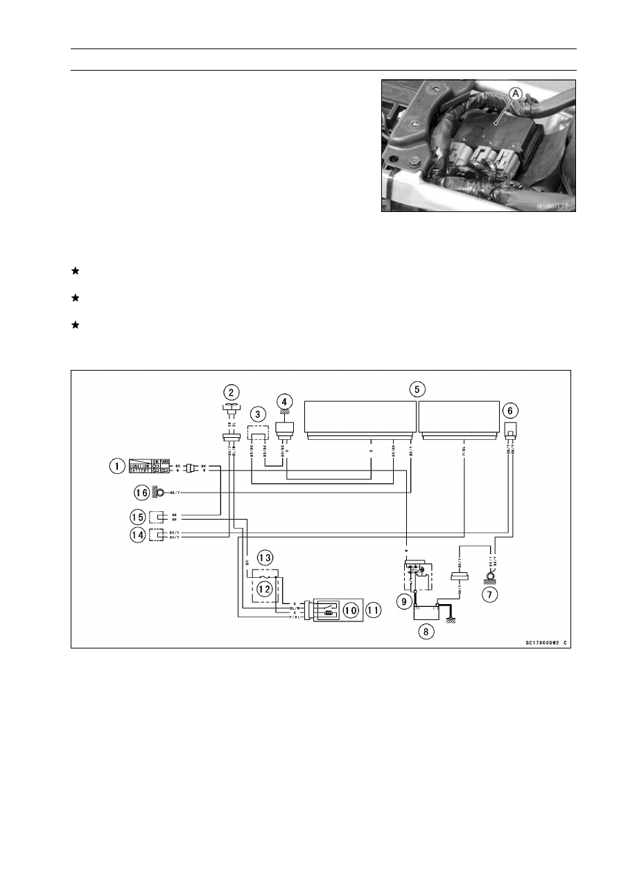
Radiator Fan Relay (Service Code 56)

Radiator Fan Relay Removal/Installation

The radiator fan relay is built in the relay box [A].

Refer to the Relay Box Removal in the Electrical System
chapter.

Radiator Fan Relay Inspection

Refer to the Relay Circuit Inspection in the Electrical Sys-
tem chapter.
If the radiator fan relay is normal, check the wiring for
continuity (see wiring diagram in this section).
If the wiring is good, check the ECU for its ground and
power supply (see ECU Power Supply Inspection).
If the ground and power supply are good, replace the ECU
(see ECU Removal/Installation).

Radiator Fan Relay Circuit

1. Ignition Switch
2. Fan Motor
3. Water-proof Joint E
4. Water Temperature Sensor
5. ECU
6. Joint Connector
7. Frame Ground
8. Battery 12 V 10 Ah

9. Main Fuse 30 A

10. Radiator Fan Relay

11. Relay Box

12. Radiator Fan Fuse 15 A
13. Fuse Box
14. Water-proof Joint A
15. Water-proof Joint C
16. Frame Ground

3-72 FUEL SYSTEM (DFI)

Subthrottle Valve Actuator (Service Code 62)

Subthrottle Valve Actuator Removal

CAUTION

Do not remove the subthrottle valve actuator [A]
since it has been adjusted and set with precision
at the factory.
Never drop the throttle body assy, especially on a
hard surface.

Such a shock to the actuator can

damage it.

Subthrottle Valve Actuator Inspection

NOTE

Be sure the battery is fully charged.

Remove the air cleaner housing (see Air Cleaner Housing
Removal).

Turn the ignition switch ON.

Check to see that all the subthrottle valves [A] open and
close smoothly.
If the subthrottle valves do not operate, check the sub-
throttle valve actuator resistance (see Subthrottle Valve
Actuator Resistance Inspection).

Subthrottle Valve Actuator Resistance Inspection

Turn the ignition switch OFF.

Remove the air cleaner housing (see Air Cleaner Housing
Removal).

Disconnect the subthrottle valve actuator connector [A].

Connect a digital meter to the subthrottle valve actuator
connector [A].

Measure the subthrottle valve actuator resistance.

Subthrottle Valve Actuator Resistance

Connections:

BK lead [1]

←→

P lead [2]

G lead [3]

←→

W/BL lead [4]

Standard:

About 5.5

7.5

If the reading is out of the standard, replace the throttle
body assy (see Throttle Body Assy Removal/Installation).
If the reading is within the range, check the input voltage
(see Subthrottle Valve Actuator Input Voltage Inspection).

FUEL SYSTEM (DFI) 3-73

Subthrottle Valve Actuator (Service Code 62)

Subthrottle Valve Actuator Input Voltage
Inspection

NOTE

Be sure the battery is fully charged.

Turn the ignition switch OFF.

Disconnect the subthrottle valve actuator connector and
connect the harness adapter [A] between these connec-
tors as shown in the figure.

Main Harness [B]
Subthrottle Valve Actuator [C]

Special Tool - Measuring Adapter: 57001-1700

Connect the peak voltage adapter [D] and a digital meter
[E] to the harness adapter leads.

Special Tool - Peak Voltage Adapter: 57001-1415

Type: KEK-54-9-B

Subthrottle Valve Actuator Input Voltage

Connections to Adapter:

(I) Digital Meter (+)

R (harness P) lead

Digital Meter (–)

BK (harness BK/BL) lead

(II) Digital Meter (+)

W (harness W/BL) lead

Digital Meter (–)

Y (harness G/Y) lead

Measure the actuator input voltage with the engine
stopped and with the connector joined.

Turn the ignition switch ON.

Input Voltage

Standard:

About DC 8.5

10.5 V

Turn the ignition switch OFF.
If the reading is in specification, but the actuator does not
operate, replace the throttle body assy (see Throttle Body
Assy Removal/Installation).

If the reading is out of the specification, remove the ECU
and check the wiring for continuity between main harness
connectors.

Special Tool - Hand Tester: 57001-1394

Disconnect the ECU and actuator connectors.

Wiring Continuity Inspection

ECU Connector [A]

←→

Subthrottle Valve Actuator Connector [B]

BK/BL lead (ECU terminal 1) [C]

G/Y lead (ECU terminal 2) [D]

P lead (ECU terminal 14) [E]

W/BL lead (ECU terminal 15) [F]

If the wiring is good, check the ECU for its ground and
power supply (see ECU Power Supply Inspection).
If the ground and power supply are good, replace the ECU
(see ECU Removal/Installation).

3-74 FUEL SYSTEM (DFI)

Subthrottle Valve Actuator (Service Code 62)

Subthrottle Valve Actuator Circuit

1. ECU
2. Subthrottle Valve Actuator

FUEL SYSTEM (DFI) 3-75

Air Switching Valve (Service Code 64)

Air Switching Valve Removal/Installation

Refer to the Air Switching Valve Removal/Installation in
the Engine Top End chapter.

Air Switching Valve Inspection

Refer to the Air Switching Valve Operation Test/Unit Test
in the Electrical System chapter.

Remove the fuel tank (see Fuel Tank Removal) and check
the wiring continuity, using the following diagram.

Air Switching Valve Circuit

1. ECU
2. Joint Connector
3. Frame Ground
4. Main Fuse 30 A
5. Battery 12V 10Ah
6. ECU Main Relay
7. Relay Box
8. ECU Fuse 15 A
9. Fuse Box

10. Water-proof Joint B

11. Water-proof Joint C

12. Frame Ground
13. Ignition Switch
14. Air Switching Valve

3-76 FUEL SYSTEM (DFI)

Oxygen Sensor Heater (Service Code 67) (Equipped Models)

Oxygen Sensor Heater Removal/Installation

The oxygen sensor heater is bult in the oxygen sensor.

So, the heater itself can not be removed. Remove the oxy-
gen sensor (see Oxygen Sensor Removal in the Electrical
System chapter).

Oxygen Sensor Heater Inspection

Turn the ignition switch off.

Disconnect the oxygen sensor lead connector [A].

Connect a digital meter [A] to the oxygen sensor lead con-
nector [B].

Measure the oxygen sensor heater resistance.

Oxygen Sensor Heater Resistance

Connections: BK lead [C]

←→

BK lead [D]

Standard: 11.7

14.5

at 20°C (68°F)

If the reading is out of the standard, replace the sensor.
If the reading is within the standard, check the power
source voltage (see Oxygen Sensor Heater Power
Source Voltage Inspection).

Oxygen Sensor Heater Power Source Voltage
Inspection

NOTE

Be sure the battery is fully charged.

Turn the ignition switch OFF.

Disconnect the oxygen sensor lead connector and con-
nect the harness adapter [A] between these connectors.

Special Tool - Oxygen Sensor Measuring Adapter: 57001

-1682

Connect a digital meter to the harness adapter lead.

Oxygen Sensor Power Source Voltage

Connections to Adapter:

Digital Meter (+)

W (sensor BK) lead

Digital Meter (–)

Battery (–) terminal

Measure the power source voltage with the engine
stopped and with the connector joined.

Turn the ignition switch ON.

Power Source Voltage

Standard: Battery Voltage

Turn the ignition switch OFF.
If the reading is in specification, but the problem still ex-
ists, replace the ECU (see ECU Removal/Installation).
If the reading is out of the standard, check the following.

Oxygen Sensor Heater Fuse 10 A (see Fuse Inspection
in the Electrical System chapter)
Power Source Wiring (see wiring diagram in this section)

FUEL SYSTEM (DFI) 3-77

Oxygen Sensor Heater (Service Code 67) (Equipped Models)

If the fuse and wiring are good, remove the ECU and
check the wiring for continuity between main harness con-
nectors.

Special Tool - Hand Tester: 57001-1394

Disconnect the ECU and sensor connectors.

Wiring Continuity Inspection

ECU Connector [A]

←→

Oxygen Sensor Connector [B]

P/BK lead (ECU terminal 23) [C]

If the wiring is good, check the ECU for its ground and
power supply (see ECU Power Supply Inspection).
If the ground and power supply are good, replace the ECU
(see ECU Removal/Installation).

Oxygen Sensor Circuit

1. Ignition Switch
2. Water-proof Joint E
3. Oxygen Sensor
4. ECU
5. Frame Ground
6. Main Fuse 30 A
7. Battery
8. Fuse Box
9. Oxygen Sensor Heater Fuse 10 A

10. Water-proof Joint C

11. Frame Ground

3-78 FUEL SYSTEM (DFI)

Oxygen Sensor-Incorrect Output Voltage (Service Code 94) (Equipped Models)

Oxygen Sensor Removal/Installation

Refer to the Oxygen Sensor Removal/Installation in the
Electrical System chapter.

Oxygen Sensor Inspection

Warm up the engine thoroughly until the radiator fan
starts.

Turn the ignition switch OFF.

Disconnect the oxygen sensor connector and connect the
harness adapter [A] between these connectors.

Special Tool - Oxygen Sensor Measuring Adapter: 57001

-1682

Connect a digital meter to the harness adapter lead.

Oxygen Sensor Output Voltage

Connections to Adapter:

Meter (+)

BL (sensor BL) lead

Meter (−)

BR (sensor W) lead

Remove the air switching valve hose from the fitting.

Install the suitable plug [A] on the fitting [B] and shut off
the secondary air.

Turn the ignition switch ON.

Start the engine, and let it idle.

Measure the output voltage with the connector joined.

Output Voltage (with Plug)

Standard:

DC 0.7 V or more

Next, remove the plug from the fitting [A] with idling.

Measure the output voltage with the connector joined.

Output Voltage (without Plug)

Standard:

DC 0.2 V or less

Turn the ignition switch OFF.
If the reading is out of the standard (with plug: DC 0.7 V or
more, without plug: DC 0.2 V or less), check the following.

Fuel Pressure (see Fuel Pressure Inspection)
Fuel Injector (see Fuel Injectors section)

If the fuel pressure and fuel injectors are good, replace
the sensor.
If the reading is within the standard (with plug: DC 0.7 V
or more, without plug: DC 0.2 V or less), check the ECU
for its ground and power supply (see ECU Power Supply
Inspection).
If the ground and power supply are good, replace the ECU
(see ECU Removal/Installation).

FUEL SYSTEM (DFI) 3-79

Oxygen Sensor-Incorrect Output Voltage (Service Code 94) (Equipped Models)

Oxygen Sensor Circuit

1. Ignition Switch
2. Water-proof Joint E
3. Oxygen Sensor
4. ECU
5. Frame Ground
6. Main Fuse 30 A
7. Battery 12 V 10 Ah
8. Fuse Box
9. Oxygen Sensor Heater Fuse 10 A

10. Water-proof Joint C

11. Frame Ground

3-80 FUEL SYSTEM (DFI)

FI Indicator Light (LED)

FI Indicator Light (LED) Inspection

Refer to the Electronic Combination Meter Unit Inspection
in the Electrical System chapter.

FI Indicator Light (LED) Circuit

1. ECU
2. Frame Ground
3. Battery 12V 10 Ah
4. Main Fuse 30 A
5. Fuse Box
6. Ignition Fuse 10 A
7. Meter Unit
8. Water-proof Joint C
9. Frame Ground

10. Ignition Switch

FUEL SYSTEM (DFI) 3-81

ECU

CAUTION

Never drop the ECU, especially on a hard surface.
Such a shock to the ECU can damage it.

ECU Removal

Remove:

Seat Covers (see Seat Cover Removal in the Frame
chapter)

Remove the nuts [A] and washers to lower the rear fender.

Remove the bolts [A].

Disconnect the ECU connectors [A]

Take off the ECU [B] and the bracket [C].

ECU Installation

Installation is the reverse of removal.

Fit [A] the bracket on the ECU as shown in the figure.

3-82 FUEL SYSTEM (DFI)

ECU

ECU Power Supply Inspection

Remove the seat (see Seat Removal in the Frame chap-
ter).

Visually inspect the ECU connectors.
If the connector is clogged with mud or dust, blow it off
with compressed air.

Remove the ECU (see ECU Removal).

Visually inspect the terminals [A] of the ECU connectors.
If the terminals of the main harness connectors are dam-
aged, replace the main harness.
If the terminals of the ECU connectors are damaged, re-
place the ECU.

Turn the ignition switch OFF.

Disconnect the ECU connectors [A].

Set the hand tester [B] to the × 1

range and check the

following wiring for continuity.

Special Tool - Hand Tester: 57001-1394

ECU Grounding Continuity Inspection

Connections:

(I) BK/Y leads (ECU

terminal 26, 42 or 43)

←→

Battery (–) Terminal

(II) Engine Ground

←→

Battery (–) Terminal

Criteria:

Both: 0

If no continuity, check the connectors, the engine ground
lead, or main harness, and repair or replace them if nec-
essary.

FUEL SYSTEM (DFI) 3-83

ECU

If the wiring is good, check the power source voltage of
the ECU.

NOTE

Be sure the battery is fully charged.

Connect the ECU connectors.

Connect a digital meter [A] to the connector [B] with the
needle adapter set.

Special Tool - Needle Adapter Set: 57001-1457

ECU Power Supply Inspection

Connections:

(I) Digital Meter (+)

Terminal 12 (BR/W)

Digital Meter (–)

Battery (–) terminal

(II) Digital Meter (+)

Terminal 27 (W/BK)

Digital Meter (–)

Battery (–) terminal

Ignition Switch OFF:

Terminal 12 (BR/W): 0 V

Terminal 27 (W/BK): Battery Voltage

Ignition Switch ON:

Both: Battery Voltage

If the reading is out of the specification, check the follow-
ing.

Main Fuse 30 A (see Fuse Inspection in the Electrical
System chapter)
ECU Fuse 15 A (see Fuse Inspection in the Electrical
System chapter)
ECU Main Relay (see Relay Circuit Inspection in the
Electrical System chapter)
Power Source Wiring (see wiring diagram in this sec-
tion )

If the fuse, wiring and relay are good, replace the ECU
(see ECU Removal/Installation).

3-84 FUEL SYSTEM (DFI)

ECU

ECU Power Source Circuit

1. ECU
2. Joint Connector
3. Frame Ground
4. Main Fuse 30 A
5. Battery 12 V 10Ah
6. ECU Main Relay
7. Relay Box
8. ECU Main Fuse 15 A
9. Fuse Box

10. Water-proof Joint B

11. Water-proof Joint C

12. Frame Ground
13. Ignition Switch

FUEL SYSTEM (DFI) 3-85

DFI Power Source

ECU Fuse Removal

Refer to the 15 A ECU Fuse Removal in the Electrical
System chapter.

ECU Fuse Installation

If a fuse fails during operation, inspect the DFI system to
determine the cause, and then replace it with a new fuse
of proper amperage.

Refer to the Fuse Installation in the Electrical System
chapter.

ECU Fuse Inspection

Refer to the Fuse Inspection in the Electrical System
chapter.

ECU Main Relay Removal/Installation

The ECU main relay is built in the relay box [A].

Refer to the Relay Box Removal in the Electrical System
chapter.

ECU Main Relay Inspection

Refer to the Relay Circuit Inspection in the Electrical Sys-
tem chapter.

3-86 FUEL SYSTEM (DFI)

Fuel Line

Fuel Pressure Inspection

NOTE

Be sure the battery is fully charged.

Remove:

Fuel Tank (see Fuel Tank Removal)
Fuel Hose (see Fuel Hose Replacement in the Periodic
Maintenance chapter)

Be sure to place a piece of cloth around the fuel supply
pipes of the fuel pump and the throttle body assy.

WARNING

Be prepared for fuel spillage; any spilled fuel must
be completely wiped up immediately.
When the fuel hose is disconnected, fuel spills out
from the hose and the pipe because of residual
pressure. Cover the hose connection with a piece
of clean cloth to prevent fuel spillage.

Install the fuel pressure gauge adapter [A] and fuel hoses
(Special Tool: 57001-1607) [B] between the fuel supply
pipes of the fuel pump and throttle body assy.

Secure the fuel hoses with the clamps.

Connect the pressure gauge [C] to the fuel pressure
gauge adapter.

Special Tools - Oil Pressure Gauge, 5 kgf/cm²: 57001-125

Fuel Pressure Gauge Adapter: 57001-1593
Fuel Hose: 57001-1607

WARNING

Do not try to start the engine with the fuel hoses
disconnected.

Connect the fuel pump lead connector.

Turn the engine stop switch run position.

Turn the ignition switch ON. The fuel pump will turn 3 sec-
onds, and then stop.

NOTE

Turn the ignition switch ON and inspect the fuel line
leakage after installing the special tools.

CAUTION

Do not drive the fuel pump 3 seconds or more with-
out the fuel in the fuel tank. If the fuel pump is driven
without the fuel, it may be damaged.

Start the engine, and let it idle.

Measure the fuel pressure with the engine idling.

Fuel Pressure (with Engine Idling)

Standard:

294 kPa (3.0 kgf/cm², 43 psi)

FUEL SYSTEM (DFI) 3-87

Fuel Line

NOTE

The gauge needle will fluctuate. Read the pressure at
the average of the maximum and minimum indications.

Turn the ignition switch OFF.
If the fuel pressure is much higher than specified, the fuel
pressure regulator in the fuel pump have been clogged or
stuck. Replace the fuel pump (see Fuel Pump section).
If the fuel pressure is much lower than specified, check
the following.

Fuel Line Leakage (see Fuel Injector Fuel Line Inspec-
tion)
Amount of Fuel Flow (see Fuel Flow Rate Inspection)

After above checks, measure the fuel pressure again.

Remove the fuel pressure gauge, hoses and adapter.

Install:

Fuel Hose (see Fuel Hose Replacement in the Periodic
Maintenance chapter)
Fuel Tank (see Fuel Tank Installation)

Start the engine and check for fuel leakage.

Fuel Flow Rate Inspection

WARNING

Gasoline is extremely flammable and can be explo-
sive under certain conditions. Make sure the area
is well-ventilated and free from any source of flame
or sparks; this includes any appliance with a pilot
light. Do not smoke. Turn the ignition switch OFF.
Be prepared for fuel spillage; any spilled fuel must
be completely wiped up immediately.

NOTE

Be sure the battery is fully charged.

Turn the ignition switch OFF.

Wait until the engine cools down.

Prepare a fuel hose (Special Tool: 57001-1607) and a
measuring cylinder.

Special Tool - Fuel Hose: 57001-1607

Remove:

Side Covers (see Side Cover Removal in the Frame
chapter)
Fuel Tank Bolts (see Fuel Tank Removal)

Open the fuel tank cap [A] to lower the pressure in the
tank.

Remove the fuel hose from the fuel pump (see Fuel Tank
Removal).

Be sure to place a piece of cloth around the fuel supply
pipe of the fuel pump.

WARNING

Be prepared for fuel spillage; any spilled fuel must
be completely wiped up immediately.
When the fuel hose is disconnected, fuel spills out
from the hose and the pipe because of residual
pressure. Cover the hose connection with a piece
of clean cloth to prevent fuel spillage.

3-88 FUEL SYSTEM (DFI)

Fuel Line

Connect the prepared fuel hose [A] to the fuel supply pipe
of the fuel pump.

Secure the fuel hose with a clamp.

Insert the fuel hose into the measuring cylinder [B].

WARNING

Wipe off spilled out fuel immediately. Be sure to
hold the measuring cylinder vertical.

Close the fuel tank cap.

Turn the engine stop switch to run position.

Turn the ignition switch ON.

The fuel pump should operate for 3 seconds, and then
should stop.

CAUTION

Do not drive the fuel pump 3 seconds or more with-
out the fuel in the fuel tank. If the fuel pump is driven
without the fuel, it may be damaged.

Measure the discharge for 3 seconds.

Repeat this operation several times.

Amount of Fuel Flow

Standard:

60 mL (2.0 US oz.) or more for 3 seconds

Turn the ignition switch OFF.
If the fuel flow is much less than the specified, replace the
fuel pump (see Fuel Pump Removal/Installation).

Install the fuel tank (see Fuel Tank Installation).

Start the engine and check for fuel leakage.

FUEL SYSTEM (DFI) 3-89

Fuel Pump

Fuel Pump Removal

WARNING

Gasoline is extremely flammable and can be explo-
sive under certain conditions. Make sure the area
is well-ventilated and free from any source of flame
or sparks; this includes any appliance with a pilot
light. Do not smoke. Turn the ignition switch OFF.
Disconnect the battery (–) terminal.
To make fuel spillage minimum, draw the fuel out
from the fuel tank when the engine is cold.

Be

prepared for fuel spillage; any spilled fuel must be
completely wiped up immediately.

CAUTION

Never drop the fuel pump, especially on a hard sur-
face. Such a shock to the pump can damage it.

Draw the fuel out from the fuel tank with a commercially
available electric pump.

Remove the fuel tank (see Fuel Tank Removal).

Be careful of fuel spillage from the fuel tank since fuel
still remains in the fuel tank and fuel pump. Plug the fuel
supply pipe of the fuel pump.

Turn the fuel tank upside down.

Remove:

Fuel Pump Bolts [A]
Fuel Pump [B] and gasket

Discard the fuel pump gasket.

CAUTION

Do not pull the lead of the fuel pump. If they are
pulled, the lead terminals may be damaged.

Fuel Pump Installation

Remove dirt or dust from the fuel pump [A] by lightly ap-
plying compressed air.

3-90 FUEL SYSTEM (DFI)

Fuel Pump

Replace the fuel pump gasket [A] with a new one.

Apply a non-permanent locking agent to the threads of
the fuel pump bolts.

Tighten the fuel pump bolts to a snug fit following the tight-
ening sequence shown.

Front [A]

Following the tightening sequence, tighten the fuel pump
bolts to the specified torque.

Torque - Fuel Pump Bolts: 9.8 N·m (1.0 kgf·m, 87 in·lb)

Tighten the fuel pump bolts again to check the tightness
in the order shown.

Fuel Pump Operation Inspection

NOTE

Be sure the battery is fully charged.

Turn the engine stop switch to run position.

Turn the ignition switch ON and make sure that the fuel
pump operates (make light sounds) for 3 seconds, and
then stops.

Turn the ignition switch OFF.
If the pump does not operate as described above, inspect
the operating voltage (see Fuel Pump Operating Voltage
Inspection).

FUEL SYSTEM (DFI) 3-91

Fuel Pump

Fuel Pump Operating Voltage Inspection

NOTE

Be sure the battery is fully charged.

Turn the ignition switch OFF.

Remove the left side cover (see Side Cover Removal in
the Frame chapter).

Disconnect the fuel pump lead connector and connect the
harness adapter [A] between these connectors as shown
in the figure.

Main Harness [B]
Fuel Pump [C]

Special Tool - Measuring Adapter: 57001-1700

Connect a digital meter [D] to the harness adapter leads.

Fuel Pump Operating Voltage

Connections to Adapter:

Digital Meter (+)

R (pump R) lead

Digital Meter (–)

BK (pump BK) lead

Measure the operating voltage with engine stopped and
with the connector joined.

Turn the engine stop switch run position.

Turn the ignition switch ON.

Operating Voltage

Standard: Battery Voltage for 3 seconds, and then 0 V

Turn the ignition switch OFF.
If the reading stays on battery voltage and never shows 0
V, check the fuel pump relay (see Relay Circuit Inspection
in the Electrical System chapter).
If the pump relay is normal, check the ECU for its ground
and power supply (see ECU Power Supply Inspection).
If the ground and power supply are good, replace the ECU
(see ECU Removal/Installation).
If there is still no battery voltage, check the ECU main
relay and fuel pump relay (see Relay Circuit Inspection in
the Electrical System chapter).
If the main relay and pump relay are normal, check the
wiring for continuity (see wiring diagram in this section).
If the wiring is good, check the ECU for its ground and
power supply (see ECU Power Supply Inspection).
If the ground and power supply are good, replace the ECU
(see ECU Removal/Installation).
If the reading is in specification, but the pump does not op-
erate, replace the fuel pump (see Fuel Pump Removal/In-
stallation).

3-92 FUEL SYSTEM (DFI)

Fuel Pump

Pressure Regulator Removal

The pressure regulator [A] is built into the fuel pump [B]
and cannot be removed.

Pump Screen, Fuel Filter Cleaning

The pump screen [A] and fuel filter [B] are built into the
pump and cannot be cleaned or checked.
If the pump screen or fuel filter is suspected of clogging
or being damaged, replace it with the fuel pump as a set.

FUEL SYSTEM (DFI) 3-93

Fuel Pump

Fuel Pump Circuit

1. Ignition Switch
2. Engine Stop Switch
3. ECU
4. Joint Connector
5. Fuel Pump
6. Frame Ground
7. Main Fuse 30 A
8. Battery 12 V10 Ah
9. ECU Main Relay

10. Fuel Pump Relay

11. Relay Box

12. ECU Fuse 15 A
13. Ignition Fuse 10 A
14. Fuse Box
15. Water-proof Joint B
16. Water-proof Joint C

3-94 FUEL SYSTEM (DFI)

Fuel Injectors

Fuel Injector Removal/Installation

Refer to the Throttle Body Assy Disassembly/Assembly.

Fuel Injector Audible Inspection

Start the engine, and let it to idle.

Apply the tip of a screwdriver [A] to the fuel injector [B].
Put the grip end onto your ear, and listen whether the fuel
injector is clicking or not.

A sound scope [C] can also be used.

The click interval becomes shorter as the engine speed
rises.

Do the same for the other fuel injector.
If all the injectors click at a regular intervals, the injectors
are normal.

Turn the ignition switch OFF.
If any fuel injector does not click, check the fuel injector
resistance (see Fuel Injector Resistance Inspection).

Fuel Injector Resistance Inspection

Remove:

Air Cleaner Housing (see Air Cleaner Housing Removal)

Disconnect the injector connector [A].

Connect a digital meter [B] to the injector terminal.

Measure the fuel injector resistance.

Fuel Injector Resistance

Connections:

For Fuel Injector #1

W/R

←→

BL/R Terminal

For Fuel Injector #2

W/R

←→

BL/G Terminal

Standard:

About 11.7

12.3

at 20°C (68°F)

If the reading is out of the standard, replace the injector.
If the reading is within the standard, check the power
source voltage (see Fuel Injector Power Source Voltage
Inspection).

FUEL SYSTEM (DFI) 3-95

Fuel Injectors

Fuel Injector Power Source Voltage Inspection

NOTE

Be sure the battery is fully charged.

Turn the ignition switch OFF.

Disconnect the injector connector and connect the har-
ness adapter [A] between these connectors as shown in
the figure.

Main Harness [B]
Fuel Injector #1 [C]

Special Tool - Measuring Adapter: 57001-1700

Connect a digital meter [D] to the harness adapter leads.

Fuel Injector Power Source Voltage

Connections to Adapter:

For Fuel Injector #1, #2

Digital Meter (+)

R (injector W/R) lead

Digital Meter (–)

Battery (–) terminal

Measure the power source voltage with the engine
stopped.

Turn the engine stop switch to run position.

Turn the ignition switch ON.

Power Source Voltage

Standard:

Battery Voltage for 3 seconds, and then 0 V

Turn the ignition switch OFF.
If the reading stays on battery voltage and never shows 0
V, check the fuel pump relay (see Relay Circuit Inspection
in the Electrical System chapter).
If the pump relay is normal, check the ECU for its ground
and power supply (see ECU Power Supply Inspection).
If the ground and power supply are good, replace the ECU
(see ECU Removal/Installation).
If there is still no battery voltage, check the ECU main
relay and pump relay (see Relay Circuit Inspection in the
Electrical System chapter).
If the main relay and pump relay are normal, check the
power source wiring (see wiring diagram in this section).
If the wiring is good, check the ECU for its ground and
power supply (see ECU Power Supply Inspection).
If the ground and power supply are good, replace the ECU
(see ECU Removal/Installation).
If the reading is in specification, check the output voltage
(see Fuel Injector Output Voltage Inspection).

3-96 FUEL SYSTEM (DFI)

Fuel Injectors

Fuel Injector Output Voltage Inspection

NOTE

Be sure the battery is fully charged.

Turn the ignition switch OFF.

Remove the ECU (see ECU Removal).

Do not disconnect the ECU connector.

Connect a digital meter [A] to the connector [B] with the
needle adapter set.

Special Tool - Needle Adapter Set: 57001-1457

Fuel Injector Output Voltage

Connections to ECU Connector:

For Fuel Injector #1

Digital Meter (+)

BL/R lead (ECU terminal 34)

Digital Meter (–)

Battery (–) terminal

For Fuel Injector #2

Digital Meter (+)

BL/G lead (ECU terminal 33)

Digital Meter (–)

Battery (–) terminal

Measure the output voltage with the engine stopped and
with the connector joined.

Turn the engine stop switch to run position.

Turn the ignition switch ON.

Output Voltage

Standard:

Battery Voltage for 3 seconds, and then 0 V

Turn the ignition switch OFF.
If the reading is in specification, check the ECU for its
ground and power supply (see ECU Power Supply In-
spection).
If the ground and power supply are good, replace the ECU
(see ECU Removal/Installation).

If the reading is out of the specification, remove the ECU
and check the wiring for continuity between main harness
connectors.

Special Tool - Hand Tester: 57001-1394

Disconnect the ECU and injector connectors.

Wiring Continuity Inspection

ECU Connector [A]

←→

Fuel Injector Connector [B]

For Fuel Injector #1 [C]

BL/R lead (ECU terminal 34) [D]

For Fuel Injector #2

BL/G lead (ECU terminal 33)

If the wiring is good, check the ECU for its ground and
power supply (see ECU Power Supply Inspection).
If the ground and power supply are good, replace the ECU
(see ECU Removal/Installation).

FUEL SYSTEM (DFI) 3-97

Fuel Injectors

Fuel Injector Fuel Line Inspection

Remove:

Fuel Tank (see Fuel Tank Removal)
Fuel Hose (see Fuel Hose Replacement in the Periodic
Maintenance chapter)

Be sure to place a piece of cloth around the fuel supply
pipes of the fuel pump and the throttle body assy.

WARNING

Be prepared for fuel spillage; any spilled fuel must
be completely wiped up immediately.
When the fuel hose is disconnected, fuel spills out
from the hose and the pipe because of residual
pressure. Cover the hose connection with a piece
of clean cloth to prevent fuel spillage.

Check the injector fuel line for leakage as follows.

Connect a commercially available vacuum/pressure
pump [A] to the nipple of the delivery pipe [B] with a
high-pressure fuel hose [C] (both ends connected with
the clamps [D]) as shown.

Torque - Fuel Hose Clamp Screws: 1.5 N·m (0.15 kgf·m, 13

in·lb)

Apply soap and water solution to the areas [E] as shown.

Watching the pressure gauge, squeeze the pump lever
[F], and build up the pressure until the pressure reaches
the maximum pressure.

Injector Fuel Line Maximum Pressure

Standard:

294 kPa (3.0 kgf/cm², 43 psi)

CAUTION

During pressure testing, do not exceed the maxi-
mum pressure for which the system is designed.

Watch the gauge for at least 6 seconds.
If the pressure holds steady, the fuel line is good.
If the pressure drops at once or if bubbles are found in the
area, the fuel line is leaking. Replace the fuel supply pipe
assy, injectors and related parts.

Repeat the leak test, and check the fuel line for no leak-
age.

Install:

Fuel Hose (see Fuel Hose Replacement in the Periodic
Maintenance chapter)
Fuel Tank (see Fuel Tank Installation)

Start the engine and check for fuel leakage.

3-98 FUEL SYSTEM (DFI)

Fuel Injectors

Fuel Injector Circuit

1. Ignition Switch
2. Engine Stop Switch
3. Fuel Injectors
4. ECU
5. Joint Connector
6. Frame Ground
7. Main Fuse 30 A
8. Battery 12 V10 Ah
9. ECU Main Relay

10. Fuel Pump Relay

11. Relay Box

12. ECU Fuse 15 A
13. Ignition Fuse 10 A
14. Fuse Box
15. Water-proof Joint B
16. Water-proof Joint C
17. Frame Ground

FUEL SYSTEM (DFI) 3-99

Throttle Grip and Cables

Throttle Grip Free Play Inspection

Refer to the Throttle Control System Inspection in the Pe-
riodic Maintenance chapter.

Throttle Grip Free Play Adjustment

Refer to the Throttle Control System Inspection in the Pe-
riodic Maintenance chapter.

Throttle Cable Installation

Install the throttle cables in accordance with the Cable,
Wire, and Hose Routing section in the Appendix chapter.

Install the upper ends of the throttle cables in the grip
after installing the lower ends of the throttle cables in the
throttle pulley on the throttle body assy.

After installation, adjust each cable properly (see Throttle
Control System Inspection in the Periodic Maintenance
chapter).

WARNING

Operation with incorrectly routed or improperly ad-
justed cables could result in an unsafe riding con-
dition.

Throttle Cable Lubrication

Refer to the Chassis Parts Lubrication in the Periodic
Maintenance chapter.

3-100 FUEL SYSTEM (DFI)

Throttle Body Assy

Idle Speed Inspection/Adjustment

Refer to the Idle Speed Inspection/Adjustment in the Pe-
riodic Maintenance chapter.

Synchronization Inspection/Adjustment

Refer to the Engine Vacuum Synchronization Inspection
in the Periodic Maintenance chapter.

Throttle Body Assy Removal

WARNING

Gasoline is extremely flammable and can be ex-
plosive under certain conditions. Turn the ignition
switch OFF. Disconnect the battery (–) cable ter-
minal.

Do not smoke.

Make sure the area is

well-ventilated and free from any source of flame
or sparks; this includes any appliance with a pilot
light.
Be prepared for fuel spillage: any spilled fuel must
be completely wiped up immediately.

CAUTION

Never drop the throttle body assy especially on a
hard surface. Such a shock to the body assy can
damage it.

Remove:

Air Cleaner Housing (see Air Cleaner Housing Removal)
Fuel Hose (see Fuel Hose Replacement in the Periodic
Maintenance chapter)

Open the clamps [A].

Disconnect the connectors [B].

Remove:

Left Upper Fairing Cover (see Upper Fairing Cover Re-
moval in the Frame chapter)
Main Throttle Sensor Connector [A]
Vacuum Hose [B]

FUEL SYSTEM (DFI) 3-101

Throttle Body Assy

Loosen the throttle body assy holder clamp bolts [A] on
both sides.

Remove the throttle case [A] to make a throttle cable
slack.

Free the idle adjusting screw [A] from the bracket.

Remove the right upper fairing cover (see Upper Fairing
Cover Removal in the Frame chapter).

Remove the throttle cable lower ends [A] from the throttle
pulley.

Pull off the throttle body assy from the holder.

After removing the throttle body assy, stuff pieces of lint
-free, clean cloths into the throttle body assy holders.

CAUTION

If dirt gets into the engine, excessive engine wear
and possible engine damage will occur.

If the throttle body assy is to be disassembly, loosen the
air cleaner duct clamp screws [A], and remove the air
cleaner duct [B].

3-102 FUEL SYSTEM (DFI)

Throttle Body Assy

Throttle Body Assy Installation

If the air cleaner duct [A] was removed, install it.

Install the duct clamp screws [B] in the direction as shown.

Bolt Heads [C]

Install the throttle body assy holder clamp bolts [A] in the
direction as shown.

Bolt Heads [B]

Route the leads and hoses according to Cable, Wire, and
Hose Routing section in the Appendix chapter.

Fit the accelerator cable end [A] and the decelerator cable
end [B] into the throttle pulley.

Check fuel leakage from the throttle body assy.

WARNING

Fuel spilled from the throttle body assy is haz-
ardous.

Install the idle adjusting screw to the bracket.

Install the right upper fairing cover (see Upper Fairing
Cover Installation in the Frame chapter).

Apply a thin coating of grease to the throttle cable upper
ends.

Install the upper ends [A] of the throttle cables in the grip.

Fit the projection [B] of the right switch housing into the
hole [C] of the handlebar.

Turn the throttle grip and make sure that the throttle valves
move smoothly and return by spring force.

Check the throttle grip free play (see Throttle Control Sys-
tem Inspection in the Periodic Maintenance chapter).

WARNING

Operation with an incorrectly routed cable could re-
sult in an unsafe riding condition.

Adjust:

Throttle Grip Free Play (see Throttle Control System In-
spection in the Periodic Maintenance chapter)
Idle Speed (see Idle Speed Adjustment in the Periodic
Maintenance chapter)


Content      ..     3      4      5      6     ..