Kawasaki Ninja ZX-12R Motorcycle. Service Manual (2002-2005 year) - page 4
 

  Index      Manuals     Kawasaki Ninja ZX-12R Motorcycle. Service Manual (2002-2005 year)


Search            copyright infringement  


Content      ..     2      3      4      5     ..


Kawasaki Ninja ZX-12R Motorcycle. Service Manual (2002-2005 year) - page 4


2-40 PERIODIC MAINTENANCE

Periodic Maintenance Procedures

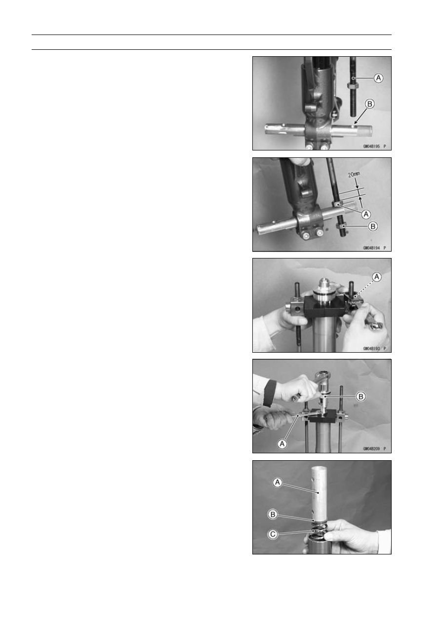
Insert the lower end of the compression shaft [A] into the
hole [B] of the holder bar.

Screw the adjust nut [A] onto the compression shaft as
shown.

Screw the locknut [B].

Set the other side compression shaft same process.

Screw in one side nut [A] come out the piston rod nut.

Holding the piston rod nut with a wrench [A], remove the
top plug [B] from the piston rod.

Remove:

Spacer [A]
Spring Seat [B]
Fork Spring [C]

PERIODIC MAINTENANCE 2-41

Periodic Maintenance Procedures

Remove:

Rebound Damping Adjuster Rod [D]

Drain the fork oil into a suitable container.

Pump the piston rod [A] up and down at least ten times to
expel the oil from the fork.

Hold the fork tube upright, press the outer tube [A] and
the piston rod all the way down.

Pour in the type and amount of fork oil specified.

Fork Oil

Viscosity

KAYABA KHL15-10 (SAE 0 W) or equivalent

Amount (per side):

When changing oil:

approx. 420 mL (14.2 US oz)

After disassembly and completely dry:

490 ±4 mL (16.6 ±0.1 US oz)

If necessary, measure the oil level as follows.

Hold the inner tube vertically in a vise.

Using the piston rod puller [A], move the piston rod [B] up
and down more than ten times in order to expel all the air
from the fork oil.

Special Tool - Fork Piston Rod Puller, M12 × 1.25: 57001

-1289

Pump the inner tube several times to expel air bubbles.

Remove the piston rod puller.

Wait until the oil level settles.

With the fork fully compressed and the piston rod fully
pushed in, insert a tape measure or rod into the inner
tube, and measure the distance from the top of the outer
tube to the oil.

2-42 PERIODIC MAINTENANCE

Periodic Maintenance Procedures

Oil Level (fully compressed, without spring)

Standard:

93 ±2 mm (3.66 ±0.08 in.)
(from the top of the outer tube)

NOTE

Fork oil lever may also be measured using the fork oil
level gauge.

Special Tool - Fork Oil Level Gauge: 57001-1290 [A]

With the fork fully compressed and without fork spring,
insert the gauge tube into the inner tube [B] and position
the stopper across the top end [F] of the outer tube [C].

Set the gauge stopper [D] so that its lower side shows the
oil level distance specified [E].

Pull the handle slowly to pump out the excess oil until the
oil no longer comes out.
If no oil is pumped out, there is insufficient oil in the inner
tube. Pour in enough oil, then pump out the excess oil as
shown above.

Install the fork spring [A] with the smaller end facing [B]
upward.

Install:

Spring Seat
Spacer

Screw the fork piston rod puller onto the end of the rod.

Special Tool - Fork Piston Rod Puller, M12 × 1.25: 57001

-1289

Pull the puller up above the inner tube top.

Remove the fork piston rod puller.

Screw the rod nut [B] onto the piston rod [A] as shown.

Insert the rebound damping adjuster rod [C] into the piston
rod.

Check the distance [C] between the bottom end [A] of the
top plug and rebound damping adjuster [B] with a pair of
vernier caliper.

13 mm (0.51 in.) [C]

PERIODIC MAINTENANCE 2-43

Periodic Maintenance Procedures

Set the fork spring compressor on the spacer using the
outer tube as a guide.

Special Tools - Fork Spring Compressor: 57001-1587

Clamp: 57001-1613

NOTE

Set the clamps so that the cutout [A] of the upper side
does not fit the hole [B] of spacer [C], pull up the outer
tube [D] to hold it by the clamps, and then tighten the
two bolts [E]. The outer tube is used as a guide.

Set the holder bar [A], and compression shafts [B].

Hold the piston rod nut [A].

Remove the piston rod puller [B].

Install the rebound damping adjuster rod [A].

2-44 PERIODIC MAINTENANCE

Periodic Maintenance Procedures

Screw in the top plug [A] stopped onto the piston rod.

Check the O-ring [B] on the top plug and replace it with a
new one if damaged.

Holding the top plug with a wrench, tighten the piston rod
nut [C] against the top plug.

Torque - Piston Rod Nut: 28 N·m (2.8 kgf·m, 21 ft·lb)

While holding up the fork spring compressor, pull out the
fork spring stopper.

Remove the fork spring compressor.

Raise the outer tube and screw the top plug into it and
install it to the steering stem.

Screw in the spring preload adjuster [A] of the top plug
so that the distance between the adjuster top and the top
plug surface [C] is 17 mm (0.67 in.) [D].

Turn in the rebound damping adjuster [B] until the fully
tightened position and turn backward the 7th click.

Install the front fork (see Front Fork Installation).

Front Fork Oil Leak Inspection

Visually inspect the front forks [A] for oil leakage, scoring
or scratches on the outer surface of the outer tubes.
Replace or repair any defective parts, if necessary.

Rear Shock Absorber Oil Leak Inspection

Visually inspect the shock absorbers [A] for oil leakage.
If they are oil leaked, one unit feels weaker than the other,
replace both shock absorber as a set.

Swingarm Pivot Lubrication

The grease nipple [A] is equipped for the lubrication of
swingarm bearing. Force grease into the nipple until the
grease comes out from right side of the swingarm pivot,
and wipe off any excess of it.

PERIODIC MAINTENANCE 2-45

Periodic Maintenance Procedures

Unit-trak Linkage Lubrication

In order for the tie-rod and rocker arm to function safely

and wear slowly, it should be lubricated in accordance with
the Periodic Maintenance Chart.

ZX1200-B1

B3

For the rocker arm and tie-rod needle bearings, there are
grease nipples [A] on the rocker arm and swingarm for
lubrication. Force grease into the nipples until it comes
out at both sides of the rocker arm and tie-rod, and wipe
off any excess.

Steering

Steering Inspection

Remove:

Lower Fairings (see Frame chapter)

Check the steering.

Lift the front wheel off the ground using the jack.

Special Tool - Jack: 57001-1238

With the front wheel pointing straight ahead, alternately
tap each end of the handlebar. The front wheel should
swing fully left and right from the force of gravity until the
fork hits the stop.
If the wheel binds or catches before the stop, the steering
is too tight.

Feel for steering looseness by pushing and pulling the
forks.
If you feel looseness, the steering is too loose.

NOTE

The cables and wiring will have some effect on the mo-
tion of the fork which must be taken into account. Be
sure the leads and cables are properly routed.

The bearings must be in good condition and properly
lubricated in order for any test to be valid.

ZX1200-B1/B2

Remove the stem head nut to take off the lock washer [A].

2-46 PERIODIC MAINTENANCE

Periodic Maintenance Procedures

Adjust the steering.

Special Tool - Steering Stem Nut Wrench: 57001-1100 [B]

If the steering is too tight, loosen the stem nut [A] a fraction
of a turn.
If the steering is too loose, tighten the nut a fraction of a
turn.

NOTE

Turn the stem nut 1/8 turn at a time maximum.

Tighten the head nut.

Torque - Steering Stem Head Nut: 54 N·m (5.5 kgf·m, 40

ft·lb)

Check the steering again
If the steering is still too tight or too loose, repeat the ad-
justment.

ZX1200-B3

Loosen the upper fork clamp bolts on both side.

Remove the stem head nut and washer.

Remove the steering stem head together with the handle-
bar installed.

Bend the claw washer tabs [A].

Remove the steering stem locknut [B] and claw washer
[C].

Adjust the stem nut [A] with the stem nut wrench [B] by
tightening to the specified torque.

Special Tool - Steering Stem Nut Wrench: 57001-1100

Torque - Steering Stem Nut: 20 N·m (2.0 kgf·m, 15 ft·lb)

NOTE

Turn the stem nut 1/8 turn at time maximum.

Install the claw washer [A] so that its bent side [B] faces
upward, and engage the bent claws with the grooves of
stem locknut [C].

Hand tighten the stem locknut until it touches the claw
washer.

Tighten the stem locknut clockwise until the claws are
aligned with the grooves of stem nut [D], and bend the
2 claws downward [E].

Tighten:

Torque - Steering Stem Head Nut: 78 N·m (8.0 kgf·m, 57

ft·lb)

Front Fork Clamp Bolts (Upper): 20 N·m (2.0

kgf·m, 14 ft·lb)

Check the steering again.
If the steering is still too tight or too loose, repeat the ad-
justment.

PERIODIC MAINTENANCE 2-47

Periodic Maintenance Procedures

Steering Stem Bearing Lubrication

Remove the steering stem.

Using a high flash-point solvent, wash the upper and
lower ball bearings in the cages, and wipe the upper and
lower outer races, which are press-fitted into the frame
head pipe, clean off old grease and dirt.

Visually check the outer races and the ball bearings.
Replace the bearing assemblies if they show wear or
damage.

Pack the upper and lower ball bearings [A] in the cages
with grease, and apply a light coat of grease to the upper
and lower outer races.

Install the steering stem, and adjust the steering.

Electrical System

Spark Plug Cleaning and Inspection

Remove the spark plug (see Electrical System chapter).

Clean the spark plug, preferably in a sandblasting device,
and then clean off any abrasive particles. The plug may
also be cleaned using a brush or other suitable tool.
If the spark plug electrodes are corroded or damaged,
or if the insulator is cracked, replace the plug. Use the
standard spark plug or optional spark plug.

Measure the gap [A] with a wire-type thickness gauge.
If the gaps are incorrect, carefully bend the side electrode
[B] with a suitable tool to obtain the correct gaps.

Spark Plug Gap: 0.7

0.9 mm (0.028

0.035 in.)

Install the spark plugs (see Electrical System chapter).

Torque - Spark Plugs: 13 N·m (1.3 kgf·m, 115 in·lb)

General Lubrication

Lubrication Perform

Before lubricating each part, clean off any rusty spots with
rust remover and wipe off any grease, oil, dirt, or grime.

Lubricate the points listed below with indicated lubricant.

NOTE

Whenever the vehicle has been operated under
wet or rainy conditions, or especially after using a
high-pressure water spray, perform the general lubri-
cation.

2-48 PERIODIC MAINTENANCE

Periodic Maintenance Procedures

Points: Lubricate with Grease.

Clutch Inner Cable Upper and Lower Ends [A]
Throttle Inner Cable Upper and Lower Ends
Choke Inner Cable Upper and Lower Ends
Clutch Lever Pivot (Apply silicone grease)
Brake Lever Pivot (Apply silicone grease)
Brake Pedal Pivot
Rear Brake Push Rod Joint
Side Stand
Tie-Rod Pivots
Rocker Arm Pivots

Cables: Lubricate with Cable Lubricant.

Choke Cable
Throttle Cables
Clutch Cable

Lubricate the cables by seeping the oil between the cable
and housing.

The cable may be lubricated by using a commercially
available pressure cable lubricator with an aerosol cable
lubricant.

With the cable disconnected at both ends, the cable
should move freely [A] within the cable housing.
If cable movement is not free after lubricating, if the cable
is frayed [B], or if the cable housing is kinked [C], replace
the cable.

Nut, Bolt, and Fastener Tightness

Tightness Inspection

Check the tightness of the bolts and nuts listed here. Also,
check to see that each cotter pin is in place and in good
condition.

NOTE

For the engine fasteners, check the tightness of them
when the engine is cold (at room temperature).

If there are loose fasteners, retighten them to the spec-
ified torque following the specified tightening sequence.
Refer to the appropriate chapter for torque specifications.
If torque specifications are not in the appropriate chapter,
see the Basic Torque for General Fasteners Table. For
each fastener, first loosen it by 1/2 turn, then tighten it.
If cotter pins are damaged, replace them with new ones.

PERIODIC MAINTENANCE 2-49

Periodic Maintenance Procedures

Nut, Bolt and Fastener to be checked

Wheels:

Front Axle Nut
Front Axle Clamp Bolts
Rear Axle Nut
Rear Axle Nut Cotter Pin

Brakes:

Front Master Cylinder Clamp Bolts
Caliper Mounting Bolts
Caliper Assembly Bolts
Rear Master Cylinder Mounting Bolts
Brake Lever Pivot Nut Locknut
Brake Pedal Mounting Bolt
Brake Rod Joint Cotter Pin

Suspension:

Front Fork Clamp Bolts
Front Fender Mounting Screws
Rear Shock Absorber Nuts
Swingarm Pivot Shaft Nut
Uni-Track Link Nuts

Steering:

Steering Stem Head Nut
Handlebar Bolts

Engine:

Engine Mounting Bolts and Nuts
Shift Pedal Bolt
Muffler Mounting Bolts
Exhaust Pipe Holder Nuts
Muffler Connecting Clamp Bolt
Clutch Lever Pivot Nut

Others:

Side Stand Mounting Bolt
Footpeg Mounting Bolts
Footpeg Bracket Mounting Bolts

FUEL SYSTEM (DFI) 3-1

3

Fuel System (DFI)

Table of Contents

Exploded View........................................................................................................................

3-4

Specifications .........................................................................................................................

3-12

Throttle Grip and Cables ........................................................................................................

3-15

Free Play Inspection .........................................................................................................

3-15

Free Play Adjustment........................................................................................................

3-15

Cable Installation ..............................................................................................................

3-15

Cable Lubrication ..............................................................................................................

3-15

Choke Cable...........................................................................................................................

3-16

Free Play Inspection .........................................................................................................

3-16

Free Play Adjustment........................................................................................................

3-16

Choke Cable Installation ...................................................................................................

3-16

Cable Lubrication ..............................................................................................................

3-16

Throttle Body Assy .................................................................................................................

3-17

Idle Speed Inspection .......................................................................................................

3-17

Throttle Bore Cleaning ......................................................................................................

3-17

Synchronization Inspection ...............................................................................................

3-17

Synchronization Adjustment .............................................................................................

3-17

Throttle Body Assy Removal.............................................................................................

3-17

Throttle Body Assy Installation..........................................................................................

3-20

Throttle Body Assy Disassembly (ZX1200-B1/B2) ...........................................................

3-22

Throttle Body Assy Disassembly (ZX1200-B3

)..............................................................

3-23

Throttle Body Assy Assembly (ZX1200-B1/B2) ................................................................

3-24

Throttle Body Assy Assembly (ZX1200-B3

)...................................................................

3-25

Air Line ...................................................................................................................................

3-26

Element Removal..............................................................................................................

3-26

Element Installation...........................................................................................................

3-26

Air Cleaner Element Cleaning and Inspection ..................................................................

3-26

Oil Draining .......................................................................................................................

3-26

Air Inlet Duct Removal ......................................................................................................

3-27

Air Inlet Duct Installation ...................................................................................................

3-27

Front Duct Removal/Installation........................................................................................

3-27

Fuel Tank ................................................................................................................................

3-28

Fuel Tank Removal ...........................................................................................................

3-28

Fuel Tank Installation ........................................................................................................

3-30

Fuel Tank Inspection .........................................................................................................

3-30

Fuel Tank Cleaning ...........................................................................................................

3-31

DFI System.............................................................................................................................

3-32

DFI Servicing Precautions ......................................................................................................

3-40

Troubleshooting the DFI System ............................................................................................

3-42

Outline .................................................................................................................................

3-42

Inquiries to Rider..................................................................................................................

3-46

DFI System Troubleshooting Guide .......................................................................................

3-49

DFI System Troubleshooting Guide ..................................................................................

3-49

Self-Diagnosis ........................................................................................................................

3-58

Self-diagnosis Outline..........................................................................................................

3-58

Self-diagnosis Function .......................................................................................................

3-58

3-2 FUEL SYSTEM (DFI)

Self-diagnosis Procedures...................................................................................................

3-59

How to Read Service Codes................................................................................................

3-61

How to Erase Service Codes...............................................................................................

3-62

Backups ...............................................................................................................................

3-64

Throttle Sensor (Service Code 11) (ZX1200-B1/B2) ..............................................................

3-67

Throttle Sensor Removal/Adjustment ...............................................................................

3-67

Input Voltage Inspection....................................................................................................

3-67

Output Voltage Inspection.................................................................................................

3-68

Resistance Inspection.......................................................................................................

3-70

Main Throttle Sensor (Service Code 11) (ZX1200-B3

)........................................................

3-72

Main Throttle Sensor Removal/Adjustment ......................................................................

3-72

Input Voltage Inspection....................................................................................................

3-72

Output Voltage Inspection.................................................................................................

3-73

Resistance Inspection.......................................................................................................

3-74

Inlet Air Pressure Sensor (Service Code 12)..........................................................................

3-75

Inlet Air Pressure Sensor Removal...................................................................................

3-75

Inlet Air Pressure Sensor Installation................................................................................

3-76

Input Voltage Inspection....................................................................................................

3-76

Output Voltage Inspection.................................................................................................

3-77

Inlet Air Temperature Sensor (Service Code 13)....................................................................

3-81

Inlet Air Temperature Sensor Removal/Installation...........................................................

3-81

Output Voltage Inspection.................................................................................................

3-81

Sensor Resistance Inspection ..........................................................................................

3-82

Water Temperature Sensor (Service Code 14) ......................................................................

3-84

Water Temperature Sensor Removal/Installation .............................................................

3-84

Output Voltage Inspection.................................................................................................

3-84

Sensor Resistance Inspection ..........................................................................................

3-86

Atmospheric Pressure Sensor (Service Code 15)..................................................................

3-87

Atmospheric Pressure Sensor Removal ...........................................................................

3-87

Atmospheric Pressure Sensor Installation ........................................................................

3-87

Input Voltage Inspection....................................................................................................

3-87

Output Voltage Inspection.................................................................................................

3-88

Crankshaft Sensor (Service Code 21)....................................................................................

3-92

Crankshaft Sensor Removal/Installation...........................................................................

3-92

Crankshaft Sensor Inspection...........................................................................................

3-92

Camshaft Position Sensor (Service Code 23) ........................................................................

3-94

Camshaft Position Sensor Removal/Installation ...............................................................

3-94

Camshaft Position Sensor Inspection ...............................................................................

3-94

Speed Sensor (Service Code 24)...........................................................................................

3-96

Speed Sensor Removal/Installation..................................................................................

3-96

Speed Sensor Inspection..................................................................................................

3-96

Gear Position Switch (Service Code 25) ................................................................................

3-98

Gear Position Switch Removal .........................................................................................

3-98

Gear Position Switch Installation ......................................................................................

3-98

Gear Position Switch Input Voltage Inspection .................................................................

3-99

Gear Position Switch Inspection .......................................................................................

3-100

Vehicle-down Sensor (Service Code 31)................................................................................

3-103

Vehicle-down Sensor Removal .........................................................................................

3-103

Vehicle-down Sensor Installation ......................................................................................

3-104

Vehicle-down Sensor Inspection.......................................................................................

3-104

Subthrottle Sensor (Service Code 32) (ZX1200-B3

...........................................................

3-108

Subthrottle Sensor Removal/Adjustment ..........................................................................

3-108

Input Voltage Inspection....................................................................................................

3-108

Output Voltage Inspection.................................................................................................

3-109

Resistance Inspection.......................................................................................................

3-110

Immobilizer Amplifier (Service Code 35) (ZX1200-B3

)........................................................

3-111

Antenna Resistance Inspection ........................................................................................

3-111

FUEL SYSTEM (DFI) 3-3

Amplifier Input Voltage Inspection.....................................................................................

3-111

Blank Key Detection (Service Code 36) (ZX1200-B3

).........................................................

3-112

User Key Inspection..........................................................................................................

3-112

Fuel Injectors (#1, #2, #3, #4: Service Code 41, 42, 43, 44)..................................................

3-113

Power Source Voltage Inspection .....................................................................................

3-113

Output Voltage Inspection.................................................................................................

3-115

Audible Inspection.............................................................................................................

3-116

Injector Signal Test............................................................................................................

3-117

Injector Resistance Inspection ..........................................................................................

3-117

Injector Unit Test ...............................................................................................................

3-118

Injector Fuel Line Inspection .............................................................................................

3-118

Fuel Pump Relay (Service Code 45, 46) ................................................................................

3-121

Fuel Pump Relay Removal ...............................................................................................

3-121

Operating Voltage Inspection............................................................................................

3-121

Power Source Voltage Inspection .....................................................................................

3-123

Relay Inspection ...............................................................................................................

3-124

Stick Coils (#1, #2, #3, #4: Service Code 51, 52, 53, 54) ......................................................

3-126

Removal/Installation..........................................................................................................

3-126

Input Voltage Inspection....................................................................................................

3-126

Subthrottle Valve Actuator (Service Code 62) (ZX1200-B3

...............................................

3-130

Subthrottle Valve Actuator Removal .................................................................................

3-130

Audible Inspection.............................................................................................................

3-130

Visual Inspection...............................................................................................................

3-130

Resistance Inspection.......................................................................................................

3-130

Input Voltage Inspection....................................................................................................

3-131

ECU ........................................................................................................................................

3-132

ECU Removal ...................................................................................................................

3-132

ECU Installation ................................................................................................................

3-132

ECU Power Supply Inspection..........................................................................................

3-132

DFI Power Source ..................................................................................................................

3-136

ECU Fuse Removal ..........................................................................................................

3-136

ECU Fuse Installation .......................................................................................................

3-136

ECU Fuse Inspection ........................................................................................................

3-136

ECU Main Relay Removal ................................................................................................

3-136

ECU Main Relay Inspection ..............................................................................................

3-136

FI Indicator LED Light.............................................................................................................

3-137

LED Light Inspection.........................................................................................................

3-138

Fuel Line.................................................................................................................................

3-140

Fuel Pressure Inspection ..................................................................................................

3-140

Fuel Flow Rate Inspection ................................................................................................

3-141

In-tank Fuel Pump ..................................................................................................................

3-143

Fuel Pump Removal .........................................................................................................

3-143

Pump Screen Cleaning .....................................................................................................

3-144

Fuel Pump Installation ......................................................................................................

3-144

Operation Inspection.........................................................................................................

3-145

Operating Voltage Inspection............................................................................................

3-145

Evaporative Emission Control System ...................................................................................

3-148

Parts Removal/Installation ................................................................................................

3-148

Hose Inspection ................................................................................................................

3-148

Separator Inspection.........................................................................................................

3-148

Separator Operation Test..................................................................................................

3-149

Canister Inspection (California Model Only) .....................................................................

3-149

3-4 FUEL SYSTEM (DFI)

Exploded View

ZX1200-B1

B2

FUEL SYSTEM (DFI) 3-5

Exploded View

Torque

No.

Fastener

N·m

kgf·m

ft·lb

Remarks

1

Inlet Air Pressure Sensor Bolt

12

1.2

106 in·lb

2

Inlet Air Temperature Sensor Bracket Nut

12

1.2

106 in·lb

3

Atmospheric Pressure Sensor Bolts

12

1.2

106 in·lb

4

Gear Position Switch Screws

4.0

0.40

35 in·lb

5

Crankshaft Sensor Bolts

6.0

0.60

53 in·lb

6

Camshaft Position Sensor Bolt

12

1.2

106 in·lb

7

Camshaft Position Sensor Rotor Bolt

12

1.2

106 in·lb

8

Delivery Pipe Screws

5.0

0.50

44 in·lb

9

Nipple Assy Screws

3.4

0.35

31 in·lb

10 Speed Sensor Bolt

10

1.0

89 in·lb

11 Inlet Air Temperature Sensor

7.8

0.80

69 in·lb

12. ECU (Electrical Control Unit)
13. Throttle Cable (accelerator)
14. Throttle Cable (decelerator)
15. Choke Cable
16. Vehicle-down Sensor

T1: 12 N·m (1.2 kgf·m, 106 in·lb)
T2: 4.0 N·m (0.40 kgf·m, 35 in·lb)
T3: 6.0 N·m (0.60 kgf·m, 53 in·lb)
T4: 10 N·m (1.0 kgf·m, 89 in·lb)

CL: Apply cable lubricant.

G: Apply grease.

L: Apply a non-permanent locking agent.

SS: Apply silicone sealant.

3-6 FUEL SYSTEM (DFI)

Exploded View

ZX1200-B3

FUEL SYSTEM (DFI) 3-7

Exploded View

Torque

No.

Fastener

N·m

kgf·m

ft·lb

Remarks

1

Inlet Air Pressure Sensor Bolt

12

1.2

106 in·lb

2

Inlet Air Temperature Sensor Bracket Nut

12

1.2

106 in·lb

3

Atmospheric Pressure Sensor Bolts

12

1.2

106 in·lb

4

Gear Position Switch Screws

4.0

0.40

35 in·lb

L

5

Crankshaft Sensor Bolts

6.0

0.60

53 in·lb

6

Camshaft Position Sensor Bolt

12

1.2

106 in·lb

7

Camshaft Position Sensor Rotor Bolt

12

1.2

106 in·lb

L

8

Delivery Pipe Screws

3.4

0.35

31 in·lb

9

Nipple Assy Screws

3.4

0.35

31 in·lb

10 Speed Sensor Bolt

10

1.0

89 in·lb

11 Inlet Air Temperature Sensor

7.8

0.80

69 in·lb

12. ECU (Electrical Control Unit)
13. Throttle Cable (accelerator)
14. Throttle Cable (decelerator)
15. Choke Cable
16. Vehicle-down Sensor

CL: Apply cable lubricant.

EO: Apply engine oil.

G: Apply grease.

L: Apply a non-permanent locking agent.

R: Replacement Parts

SS: Apply silicone sealant.

3-8 FUEL SYSTEM (DFI)

Exploded View

FUEL SYSTEM (DFI) 3-9

Exploded View

1. Air Cleaner Elements
2. Ducts
3. Air Switching Valve

AO: Apply high-quality-form-air-filter oil.

CAL: California Model

A: ZX1200-B1/B2
B: ZX1200-B3

3-10 FUEL SYSTEM (DFI)

Exploded View

FUEL SYSTEM (DFI) 3-11

Exploded View

Torque

No.

Fastener

N·m

kgf·m

ft·lb

Remarks

1

Fuel Level Sensor Bolts

6.9

0.70

61 in·lb

L

2

Fuel Pump Bolts

6.9

0.70

61 in·lb

L, S

3

Fuel Hose Clamp Bolts

1.5

0.15

13 in·lb

4. Fuel Pump
5. Separator
6. Canister
L: Apply a non-permanent locking agent.

R: Replacement Parts

S: Tighten the fasteners following the specified sequence.

CAL: California Model

3-12 FUEL SYSTEM (DFI)

Specifications

Item

Standard

Throttle Grip and Cables

Throttle Grip Free Play

2

3 mm (0.08

0.12 in.)

Choke Cable

Choke Cable Free Play

2

3 mm (0.08

0.12 in.)

Digital Fuel Injection System

Idle Speed

1 000 ±50 r/min (rpm)

Throttle Assy:

Type

Four barrel type

Bore

46 mm (1.8 in.)

Throttle Body Vacuum

26 ±1.333 kPa (195 ±10 mmHg)

Bypass Screws:

ZX1200-B1/B2

– – –

ZX1200-B3

0

2 1/2 (for reference)

ECU (Electronic Control Unit):

Make

Denso

Type

Digital memory type, with built in IC igniter, sealed with resin

Usable Engine Speed:

ZX1200-B1/B2

100

11 870 r/min (rpm)

ZX1200-B3

100

11 840 r/min (rpm)

Fuel Pump:

Type

In-tank pump (in fuel tank), or Wesco pump (friction pump)

Discharge

83 mL (2.8 US oz) or more/3 seconds

Fuel Pressure (High Pressure Line):

Right after Ignition Switch ON, with
Fuel Pump Running for 3 seconds

285

315 kPa (2.91

3.21 kgf/cm², 41

46 psi)

Throttle Sensor (ZX1200-B1/B2):

Non-adjustable, and non-removable

Input Voltage

4.75

5.25 V DC between BL/W and BR/BK leads

Output Voltage

1.07

4.61 V DC between Y/W and BR/BK leads (idle

throttle opening to full throttle opening)

Resistance

4

6 k

Main Throttle Sensor (ZX1200-B3

):

Non-adjustable, and non-removable

Input Voltage

4.75

5.25 V DC between BL/W and BR/BK leads

Output Voltage at Idle Throttle
Opening

1.06

1.10 V DC between Y/W and BR/BK leads

Output Voltage at Full Throttle
Opening

4.26

4.86 V DC between Y/W and BR/BK leads

Resistance

4

6 k

Sub Throttle Sensor (ZX1200-B3

): Non-adjustable, and non-removable

Input Voltage

4.75

5.25 V DC between BL/W and BR/BK leads

Output Voltage at Idle Throttle
Opening

0.48

0.52 V DC between BR and BR/BK leads

Output Voltage at Full Throttle
Opening

3.6

4.0 V DC between BR and BR/BK leads

Resistance

4

6 k

FUEL SYSTEM (DFI) 3-13

Specifications

Item

Standard

Sub Throttle Valve Actuator
(ZX1200-B3

):

Resistance

about 2

4 k

Input Voltage

about 10

14 V DC

Atmospheric Pressure Sensor/Inlet
Air Pressure Sensor:

Input Voltage

4.75

5.25 V DC between BL/W and BR/BK lead

Output Voltage

3.46

3.82 V DC at standard atmospheric pressure (see

this text for details)

Inlet Air Temperature Sensor:

Resistance

657

1 003 k

at 0°C (32°F)

68

89 k

at 50°C (122°F)

11.95

14.37 k

at 100°C (212°F)

Output Voltage at ECU

about 2.26

2.50 V @20°C (68°F)

Water Temperature Sensor:

Resistance

2.32

2.59 k

at 20°C (68°F)

0.31

0.326 k

at 80°C (176°F)

0.1399

0.1435 k

at 110°C (230°F)

Output Voltage at ECU

about 1.95

2.29 V @20°C (68°F)

Vehicle-down Sensor:

Detection Method

Magnetic flux detection method

Detection Angle

more than 65° ±5° for each bank

Detection Time

within 0.5

1.0 seconds

Output Voltage

with the sensor tilted 60

70° or more: 3.7

4.4 V

with sensor arrow mark pointed up: 0.4

1.4 V

Fuel Injectors:

Type:

ZX1200-B1/B2

46EIS × 4

ZX1200-B3

INP-284

Nozzle Type:

ZX1200-B1/B2

One spray type with 4 holes

ZX1200-B3

One spray type with 12 holes

Resistance:

ZX1200-B1/B2

about 12.5

at 20°C (68°F)

ZX1200-B3

about 11.7

12.3

at 20°C (68°F)

Immobilizer Amplifier:

Antenna Resistance

about 0.6

0.9

3-14 FUEL SYSTEM (DFI)

Specifications

Special Tools - Oil Pressure Gauge: 57001-125

Carburetor Drain Plug Wrench, Hex 3: 57001-1269
Fork Oil Level Gauge: 57001-1290
Pilot Screw Adjuster, C: 57001-1292
Hand Tester: 57001-1394
Throttle Sensor Setting Adapter: 57001-1521
Peak Voltage Adapter: 57001-1415
Needle Adapter Set: 57001-1457
Throttle Sensor Setting Adapter: 57001-1538
Fuel Pressure Gauge Adapter: 57001-1593
Fuel Hose: 57001-1607

Sealant - Kawasaki Bond (Silicone Sealant): 56019-120

FUEL SYSTEM (DFI) 3-15

Throttle Grip and Cables

Free Play Inspection

Refer to the Throttle Control System Inspection in the Pe-
riodic Maintenance chapter.

Free Play Adjustment

Refer to the Throttle Control System Inspection in the Pe-
riodic Maintenance chapter.

Cable Installation

Install the throttle cables in accordance with the Cable
Routing section in the General Information chapter.

Install the lower ends of the throttle cables in the cable
bracket on the throttle assy after installing the upper ends
of the throttle cables in the grip.

After installation, adjust each cable properly.

WARNING

Operation with incorrectly routed or improperly ad-
justed cables could result in an unsafe riding con-
dition.

Cable Lubrication

Refer to the General Lubrication Perform in the Periodic
Maintenance chapter.

3-16 FUEL SYSTEM (DFI)

Choke Cable

Free Play Inspection

Push the choke lever [A] all the way to the front.

Check choke cable free paly [B].
If the free play is incorrect, adjust the choke cable.

Choke Cable Free Play

Standard:

2

3 mm (0.08

0.12 in.)

Free Play Adjustment

Remove the right upper and lower inner cover (see Frame
chapter).

Loosen the locknut [A], and turn the adjuster [B] until the
cable has the proper amount of free play.

Tighten the locknut securely.

ZX1200-B3 [C]

Choke Cable Installation

Install the choke cable in accordance with the Cable Rout-
ing section in the General Information chapter.

After installation, adjust the cable properly.

WARNING

Operation with an incorrectly routed or improperly
adjusted cable could result in an unsafe riding con-
dition.

Cable Lubrication

Refer to the General Lubrication Perform in the Periodic
Maintenance chapter.

FUEL SYSTEM (DFI) 3-17

Throttle Body Assy

Idle Speed Inspection

Refer to the Idle Speed Inspection in the Periodic Main-
tenance chapter.

Throttle Bore Cleaning

Refer to the Throttle Control System Inspection in the Pe-
riodic Maintenance chapter.

Synchronization Inspection

Refer to the Engine Vacuum Synchronization Inspection
in the Periodic Maintenance chapter.

Synchronization Adjustment

Refer to the Engine Vacuum Synchronization Inspection
in the Periodic Maintenance chapter.

Throttle Body Assy Removal

WARNING

Gasoline is extremely flammable and can be ex-
plosive under certain conditions. Turn the ignition
switch OFF. Disconnect the battery (–) cable ter-
minal.

Do not smoke.

Make sure the area is

well-ventilated and free from any source of flame
or sparks; this includes any appliance with a pilot
light.
Be prepared for fuel spillage: any spilled fuel must
be completely wiped up immediately.

Remove:

Seats (see Frame chapter)
Fuel Tank Cover (see Fuel Tank Removal)

Set up the fuel tank [A] with the supporting rod [B].

CAUTION

Do not insert the supporting rod into the bolt hole,
or the thread of the bolt hole could damaged.

Disconnect the inlet air temperature sensor connector [A].

Remove:

Air Cleaner Cap Bolts [B]
Right and Left Air Cleaner Caps [C]

3-18 FUEL SYSTEM (DFI)

Throttle Body Assy

Unscrew the duct bolts [A].

Pull out the ducts [B] upward.

ZX1200-B1/B2

Remove the brackets [A] from the stoppers [B].

Disconnect the throttle sensor connector [A].

Pull out the vacuum hose [B] from the inlet air pressure
sensor.

Disconnect the injector lead connector [A].

Loosen the holder clamp Allen bolts [B].

Special Tool - Carburetor Drain Plug Wrench, Hex 3:

57001-1269

WARNING

Fuel spilled from the fuel hoses are hazardous.

Remove the choke cable lower end [A] with pushing the
choke lever forward to make a cable slack.

Remove the throttle case to make a throttle cable slack.

Remove the throttle cable lower ends [B].

Be sure to place a piece of cloth around the fuel supply
hose pipe of the throttle body assy.

Pull off the fuel hose [C].

Plug the pipe of the throttle body quickly with a suitable
plug.

Drain the fuel in hose into a suitable container.

FUEL SYSTEM (DFI) 3-19

Throttle Body Assy

Pull the throttle body assy out of the holders, and then
remove it to the right side.

Removing the throttle body assy halfway, pull out the
three vacuum hoses [A] and flatten the clamp [B] to free
the throttle body from the vacuum hoses.

After removing the throttle body assy, stuff pieces of lint
-free, clean cloths into the throttle body holders and wrap
the air cleaner holes with the clean cloth.

CAUTION

If dirt gets into the engine, excessive engine wear
and possible engine damage will occur.

ZX1200-B3

Remove the brackets [A] from the stoppers [B].

Disconnect the main and sub throttle sensor connectors
[A].

Pull out the vacuum hose from the inlet air pressure sen-
sor.

Loosen the holder clamp Allen bolts [A].

Special Tool - Carburetor Drain Plug Wrench, Hex 3:

57001-1269

WARNING

Fuel spilled from the fuel hoses are hazardous.

Remove the choke cable lower end [A] with pushing the
choke lever forward to make a cable slack.

Remove the throttle case to make a throttle cable slack.

Remove the throttle cable lower ends [B].

Be sure to place a piece of cloth around the fuel supply
hose pipe of the throttle body assy.

Pull off the fuel hose [C].

Plug the pipe of the throttle body quickly with a suitable
plug.

Drain the fuel in hose into a suitable container.

3-20 FUEL SYSTEM (DFI)

Throttle Body Assy

Disconnect the connector [A].

Disconnect the injector lead connector [A].

Pull the throttle body assy out of the holders, and then
remove it to the right side.

Removing the throttle body assy halfway, flatten the
clamp [A] to free the throttle body from the hose [B].

After removing the throttle body assy, stuff pieces of lint
-free, clean cloths into the throttle body holders and wrap
the air cleaner holes with the clean cloth.

CAUTION

If dirt gets into the engine, excessive engine wear
and possible engine damage will occur.

Throttle Body Assy Installation

Install the holder clamps [A] aligning their projection with
the holder hole, the screw heads [B] on the left side as
well.

Special Tool - Carburetor Drain Plug Wrench, Hex 3:

57001-1269

For ZX1200-B3

model; as shown in the figure.

Special Tool - Carburetor Orain Plug Wrench, Hex 3:

57001-1269

FUEL SYSTEM (DFI) 3-21

Throttle Body Assy

Run the vacuum hoses and fuel hoses as shown in the
Cable, Wire, and Hose Routing section of the General
Information chapter.

Turn the throttle grip to make sure that the throttle linkages
do not contact the holder screws or hoses.

WARNING

Be sure to install the holder clamp screws in the di-
rection shown. Or, the screws could come in con-
tact with the throttle linkage resulting in unsafe rid-
ing condition.

Be sure the fuel hose [A] are clamped securely to prevent
leaks.

WARNING

Fuel spilled from the fuel hoses are hazardous.

Adjust:

Throttle Grip Free Play
Choke Lever Free Play
Idle Speed

For ZX1200-B3

model; as shown in the figure.


Content      ..     2      3      4      5     ..