Kawasaki Ninja ZX-12R Motorcycle. Service Manual (2002-2005 year) - page 2


  Index      Manuals     Kawasaki Ninja ZX-12R Motorcycle. Service Manual (2002-2005 year)


Search            copyright infringement  


Content      ..      1      2      3      ..


Kawasaki Ninja ZX-12R Motorcycle. Service Manual (2002-2005 year) - page 2


1-38 GENERAL INFORMATION

Cable, Wire, and Hose Routing (ZX1200-B3

)

GENERAL INFORMATION 1-39

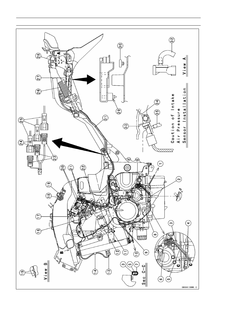
Cable, Wire, and Hose Routing (ZX1200-B3

)

1. To Side Stand Switch
2. Clamp the side stand switch lead.
3. Gear Position Switch Lead
4. Clamp the speed sensor lead, gear position switch lead and sub narness, for privent of the

speed sensor connetor movement.

5. Speed Sensor Lead
6. Clamp the leads so that the speed sensor lead is out side.
7. Sub Harness
8. Install the rubber cap of the oil pressure warning light switch as shown.
9. Clamp the harness just before the diverging point.

10. To Horn

11. Run the harness between the waler pipe and hose.

12. Clamp the horn lead and reserve tank hose.
13. Fan Switch
14. Clamp the fan switch lead.
15. Run the fan switch lead through the clamps of baffle plate.
16. Run the harness over the cover.
17. Intake Air Pressure Sensor
18. Intake Air Temperature Sensor
19. After connecting the connector insert it into the damper.
20. Sub Throttle Sensor
21. Main Throttle Sensor
22. Water Temperature Sensor
23. From Alternator.
24. White Connector
25. From Regulator/Rectifier
26. Regulator/Rectifier
27. ECU
28. Atmospheric Pressure Sensor
29. Insert the dumpers of the ECU into the holes of the fender.
30. Damper (Other than Europe and United Kingdom Model)
31. Through the harness into the clamp.
32. Position the tube end downward.
33. Touch the stopper of the bracket onto the frame.
34. Tighten the sensor bracket bolt with the ground lead.
35. Connect the vacuum tube of the throttle body.

1-40 GENERAL INFORMATION

Cable, Wire, and Hose Routing

GENERAL INFORMATION 1-41

Cable, Wire, and Hose Routing

1-42 GENERAL INFORMATION

Cable, Wire, and Hose Routing (ZX1200-B1/B2)

GENERAL INFORMATION 1-43

Cable, Wire, and Hose Routing (ZX1200-B1/B2)

1. To the reserve tank bottom.
2. Cooling Reserve Tank Hose
3. Vacuum Hose
4. To the radiator filler neck portion.
5. To the radiator.
6. Clamp
7. To the hole of frame.
8. Tube
9. Clamp (Position the claw rearward.)

10. Clamp

11. Clamp

12. Position the clamp screws as shown.
13. Cooling Tube
14. Cooling Pipe
15. Flat Side
16. Radiator Cap
17. Run the lead front the bracket.
18. Radiator
19. Clamp
20. To the subharness.
21. Clamps
22. To the horn.

1-44 GENERAL INFORMATION

Cable, Wire, and Hose Routing (ZX1200-B3

)

GENERAL INFORMATION 1-45

Cable, Wire, and Hose Routing (ZX1200-B3

)

1. To the reserve tank bottom.
2. Cooling Reserve Tank Hose
3. Air Suction Vanlve
4. To the radiator filler neck portion.
5. To the radiator.
6. To the hole of frame.
7. Tube
8. Clamp (Position the claw rearward.)
9. About 45°

10. Clamp

11. Position the clamp screws as shown.

12. Cooling Tube
13. Cooling Pipe
14. Flat Side
15. Radiator Cap
16. Run the lead front the bracket.
17. Radiator
18. Clamp
19. To the sub harness.
20. Clamps
21. To the horn.

1-46 GENERAL INFORMATION

Cable, Wire, and Hose Routing (ZX1200-B1/B2)

GENERAL INFORMATION 1-47

Cable, Wire, and Hose Routing (ZX1200-B1/B2)

1. Run the vaccum sensor lead above the evaporative tube (California model only).
2. Clamp (Position the claw rearward.)
3. Run the fan leads as shown.
4. To the separator (California model only)
5. To Main Harness
6. Fan Relay (Signal) Connector
7. Run the engine sub harness outside the lib of the head cover.
8. Run the starter motor cable under the engine sub harness.
9. Fix the crankshaft sensor lead connector.

10. Engine Sub Harness Connector

11. Gear Position Switch Lead Connector

12. To Headlight Relay
13. Run the headlight relay lead under the fuel tube.
14. Alternator Lead Connector
15. Speed Sensor
16. Run the speed sensor lead back the bolt and under the gear position switch lead for privent of

the lead lift up.

17. California Model only
18. Other than California Model
19. Cooling Hose
20. Harness
21. Starter Moter Cable

1-48 GENERAL INFORMATION

Cable, Wire, and Hose Routing (ZX1200-B3

)

GENERAL INFORMATION 1-49

Cable, Wire, and Hose Routing (ZX1200-B3

)

1. Air Switching Valve
2. Run the fan leads as shown.
3. Run the water hose on the fan leads and fan switch lead.
4. Fan Relay (Signal) Connector
5. To Main Harness
6. Run the engine sub harness outside the lib of the head cover.
7. To Canister (California Model only)
8. Actuator
9. To Separator (California Model only)

10. Run the starter motor cable under the engine sub harness.

11. Fix the crankshaft sensor lead connector.

12. Engine Sub Harness
13. Gear Position Switch Lead Connector
14. To Headlight Relay
15. Run the headlight relay lead under the fuel tube.
16. Alternator Lead Connector
17. Speed Sensor
18. Run the speed sensor lead back the bolt and under the gear position switch lead for privent of

the lead lift up.

19. California Model only
20. Other than California Model
21. Cooling Hose
22. Harness
23. Starter Moter Cable
24. Crankshaft Sensor Lead
25. Fuel Supply Hose
26. Tube (Throttle Body-Separator) (California Model only)

1-50 GENERAL INFORMATION

Cable, Wire, and Hose Routing

GENERAL INFORMATION 1-51

Cable, Wire, and Hose Routing

1-52 GENERAL INFORMATION

Cable, Wire, and Hose Routing

GENERAL INFORMATION 1-53

Cable, Wire, and Hose Routing

1. Face the clamp screw head rightward.
2. Connect the clamp end and position mark of tube.
3. Fuel Tank
4. Fuel Pump
5. Position the clamp screw downward.
6. Spring Protection (Put it on the fuel hose between the clamp and other after installing the

clamps.)

7. Fuel Supply Hose (Do not twist the hose, when installing it on the fitting of the fuel pump.)
8. Clamp
9. Do not pull the leads, when installing the screw of clamp.

10. Rear Fender Front

11. Black Tape

12. Clamp the cooling hoses and fuel hoses.
13. Insert the fuel hose to bottom.
14. Clamp
15. Tube (California Model only)
16. Alternator Leads
17. Gear Position Switch Lead
18. Engine Sub Harness
19. Fuel Supply Hose
20. Tube
21. Harness Bracket
22. Crank Shaft Sensor Lead
23. Tube (California Mode only)
24. Clump

F: ZX1200-B3

1-54 GENERAL INFORMATION

Cable, Wire, and Hose Routing

GENERAL INFORMATION 1-55

Cable, Wire, and Hose Routing

1-56 GENERAL INFORMATION

Cable, Wire, and Hose Routing

GENERAL INFORMATION 1-57

Cable, Wire, and Hose Routing

1-58 GENERAL INFORMATION

Cable, Wire, and Hose Routing

GENERAL INFORMATION 1-59

Cable, Wire, and Hose Routing

1. Clamps
2. Return Hose (Red)
3. Breather Hose (Blue)
4. Band C are same dimension.
5. Insert the clamp into the hole of the frame.
6. To Vacuum Switch Valve

To Air Switching Valve (ZX1200-B3

)

7. Clamp (Position the claw reaward.)
8. Clamp (Position the claw right side.)
9. Straight side.

10. To Separator

11. To Canister

12. Run the vacuum sensor lead above the evaporative tube.
13. Fitting
14. Bend the clamp outward.
15. Bend the clamp inward.
16. Bend the direction of the clamp.
17. Air Switching Valve

D: ZX1200-B3

1-60 GENERAL INFORMATION

Cable, Wire, and Hose Routing

GENERAL INFORMATION 1-61

Unit Conversion Table

Prefixes for Units:

Prefix

Symbol

Power

mega

M

× 1 000 000

kilo

k

× 1 000

centi

c

× 0.01

milli

m

× 0.001

micro

μ

× 0.000001

Units of Mass:

kg

×

2.205

=

lb

g

×

0.03527

=

oz

Units of Volume:

L

×

0.2642

=

gal (US)

L

×

0.2200

=

gal (imp)

L

×

1.057

=

qt (US)

L

×

0.8799

=

qt (imp)

L

×

2.113

=

pint (US)

L

×

1.816

=

pint (imp)

mL

×

0.03381

=

oz (US)

mL

×

0.02816

=

oz (imp)

mL

×

0.06102

=

cu in

Units of Force:

N

×

0.1020

=

kg

N

×

0.2248

=

lb

kg

×

9.807

=

N

kg

×

2.205

=

lb

Units of Length:

km

×

0.6214

=

mile

m

×

3.281

=

ft

mm

×

0.03937 =

in

Units of Torque:

N·m

×

0.1020

=

kgf·m

N·m

×

0.7376

=

ft·lb

N·m

×

8.851

=

in·lb

kgf·m

×

9.807

=

N·m

kgf·m

×

7.233

=

ft·lb

kgf·m

×

86.80

=

in·lb

Units of Pressure:

kPa

×

0.01020 =

kgf/cm²

kPa

×

0.1450

=

psi

kPa

×

0.7501

=

cmHg

kgf/cm²

×

98.07

=

kPa

kgf/cm²

×

14.22

=

psi

cmHg

×

1.333

=

kPa

Units of Speed:

km/h

×

0.6214

=

mph

Units of Power:

kW

×

1.360

=

PS

kW

×

1.341

=

HP

PS

×

0.7355

=

kW

PS

×

0.9863

=

HP

Units of Temperature:

PERIODIC MAINTENANCE 2-1

2

Periodic Maintenance

Table of Contents

Periodic Maintenance Chart (U.S.A.

and Canada Model) ........................

2-2

Periodic Maintenance Chart (Other

than U.S.A. and Canada Model).....

2-4

Specifications ....................................

2-6

Periodic Maintenance Procedures.....

2-8

Fuel System (DFI)...........................

2-8

Fuel Hose and Connection

Inspection..................................

2-8

Throttle Control System

Inspection..................................

2-9

Idle Speed Inspection ..................

2-10

Engine Vacuum Synchronization

Inspection (ZX1200-B1/B2).......

2-11

Engine Vacuum Synchronization

Inspection (ZX1200-B3

) .........

2-12

Air Cleaner Element Cleaning

(ZX1200-B1/B2)/Element
Replacement (ZX1200-B3

) ....

2-15

Evaporative Emission Control

System Inspection(CAL) ...........

2-16

Cooling System...............................

2-17

Cooling Hose and Connection

Inspection..................................

2-17

Coolant Change ...........................

2-17

Engine Top End ..............................

2-19

Air Suction Valve Inspection ........

2-19

Valve Clearance Inspection .........

2-20

Clutch..............................................

2-24

Clutch Adjust Inspection ..............

2-24

Engine Lubrication System .............

2-25

Engine Oil Change.......................

2-25

Oil Filter Replace .........................

2-25

Wheels/Tires...................................

2-26

Tire Wear Inspection ....................

2-26

Final Drive.......................................

2-27

Drive Chain Slack Inspection .......

2-27

Drive Chain Wear Inspection .......

2-28

Drive Chain Lubrication................

2-30

Brakes.............................................

2-30

Brake Hose, Connection

Inspection..................................

2-30

Brake Fluid Level Inspection........

2-31

Brake Fluid Change .....................

2-31

Front Brake Pad Wear Inspection

2-32

Rear Brake Pad Wear Inspection

2-33

Brake/Master Cylinder Cup and

Dust Cover Replace ..................

2-33

Caliper Piston/Dust Seal Replace

2-33

Front Brake Light Switch

Inspection..................................

2-33

Rear Brake Light Switch

Inspection/Adjustment...............

2-33

Suspension .....................................

2-34

Front Fork Oil Change

(ZX1200-B1/B2) ........................

2-34

Front Fork Oil Change

(ZX1200-B3

)...........................

2-39

Front Fork Oil Leak Inspection.....

2-44

Rear Shock Absorber Oil Leak

Inspection..................................

2-44

Swingarm Pivot Lubrication .........

2-44

Unit-trak Linkage Lubrication .......

2-45

Steering ..........................................

2-45

Steering Inspection ......................

2-45

Steering Stem Bearing

Lubrication.................................

2-47

Electrical System ............................

2-47

Spark Plug Cleaning and

Inspection..................................

2-47

General Lubrication ........................

2-47

Lubrication Perform......................

2-47

Nut, Bolt, and Fastener Tightness ..

2-48

Tightness Inspection ....................

2-48

2-2 PERIODIC MAINTENANCE

Periodic Maintenance Chart (U.S.A. and Canada Model)

The scheduled maintenance must be done in accordance with this chart to keep the motorcycle in

good running condition.

The initial maintenance is vitally important and must not be neglected.

FREQUENCY Whichever

comes

first

*Odometer Reading

× 1000 km

(× 1000 mile)

1

6

12

18

24

30

36

OPERATION

Every

(0.6) (4) (7.5) (12) (15) (20) (24)

Refer-

ence

Steering - inspect †

• • • • • • •

2-45

Steering stem bearing - lubricate

2 years

2-47

Brake hoses, connections - inspect †

• • • • • •

2-30

Brake fluid level - inspect †

month

• • • • • • •

2-31

Brake fluid - change

2 years

2-31

Brake pad wear - inspect † #

• • • • • •

2-32

Brake master cylinder cup and dust cover
- replace

4 years

2-33

Caliper piston fluid and dust seal - replace 4 years

2-33

Brake light switches - inspect †

• • • • • • •

2-33

Tire wear - inspect †

• • • • • •

2-26

Front fork oil - change

2 years

2-34

Front fork oil leak - inspect †

2-44

Rear shock absorber oil leak - inspect †

2-44

Swingarm pivot, Unit-track linkage -
lubricate

2-44

Clutch adjust - inspect †

• • • • • • •

2-24

Drive chain slack - inspect † #

1 000 km

2-27

Drive chain wear - inspect † #

• • • • • •

2-28

Drive chain roller wear - inspect † #

• • • • • •

2-29

Drive chain - lubricate #

600 km

2-30

Spark plug (e) - clean and gap †

• • • • • •

2-47

Fuel hoses, connections - inspect †

• • • • • •

2-8

Throttle control system (e) - inspect †

• • • • • • •

2-9

Idle speed (e) - inspect †

2-10

Engine vacuum sychronization (e) -
inspect †

2-11

Air cleaner element (e) - clean † #
(ZX1200-B1/B2)

2-15

Air cleaner element (e) - replace † #
(ZX1200-B3

)

2-15

Evaporative emission control system (e)
(CAL) - inspect †

• • • • • • •

2-16

Air suction valve (e) - inspect †

• • • • • •

2-19

Valve clearance (e) - inspect †

2-20

Cooling hoses, connections - inspect †

2-17

Coolant - change

2 years

2-17

PERIODIC MAINTENANCE 2-3

Periodic Maintenance Chart (U.S.A. and Canada Model)

FREQUENCY Whichever

comes

first

*Odometer Reading

× 1000 km

(× 1000 mile)

1

6

12

18

24

30

36

OPERATION

Every

(0.6) (4) (7.5) (12) (15) (20) (24)

Refer-

ence

Engine oil - change #

6 months

• • • • • • •

2-25

Oil filter - replace

2-25

General lubrication - perform

2-48

Nuts, bolts, and fasteners tightness -
inspect †

2-48

#: Service more frequently when operating in severe conditions; dusty, wet, muddy, high speed,

or frequent starting/stopping.

*: For higher odometer readings, repeat at the frequency interval established here.

†: Replace, add, adjust, clean, or torque if necessary.

CAL: California Model only

e: Emission Related Items

2-4 PERIODIC MAINTENANCE

Periodic Maintenance Chart (Other than U.S.A. and Canada Model)

The scheduled maintenance must be done in accordance with this chart to keep the motorcycle in

good running condition.

The initial maintenance is vitally important and must not be neglected.

FREQUENCY Whichever

comes

first

*Odometer Reading

× 1000 km

(× 1000 mile)

1

6

12

18

24

30

36

OPERATION

Every

(0.6) (4) (7.5) (12) (15) (20) (24)

Refer-

ence

Steering - inspect †

• • • • • • •

2-45

Steering stem bearing - lubricate

2 years

2-47

Brake hoses, connections - inspect †

• • • • • •

2-30

Brake fluid level - inspect †

month

• • • • • • •

2-31

Brake fluid - change

2 years

2-31

Brake pad wear - inspect † #

• • • • • •

2-32

Brake master cylinder cup and dust cover
- replace

4 years

2-33

Caliper piston fluid and dust seal - replace 4 years

2-33

Brake light switches - inspect †

• • • • • • •

2-33

Tire wear - inspect †

• • • • • •

2-26

Front fork oil - change

2 years

2-34

Front fork oil leak - inspect †

2-44

Rear shock absorber oil leak - inspect †

2-44

Swingarm pivot, Unit-track linkage -
lubricate

2-44

Clutch adjust - inspect †

• • • • • • •

2-24

Drive chain slack - inspect † #

1 000 km

2-27

Drive chain wear - inspect † #

• • • • • •

2-28

Drive chain roller wear - inspect † #

• • • • • •

2-29

Drive chain - lubricate #

600 km

2-30

Spark plug - clean and gap †

• • • • • •

2-47

Fuel hoses, connections - inspect †

• • • • • •

2-8

Throttle control system - inspect †

• • • • • • •

2-9

Idle speed - inspect †

2-10

Engine vacuum sychronization - inspect †

2-11

Air cleaner element - clean † #
(ZX1200-B1/B2)

2-15

Air cleaner element - replace † #
(ZX1200-B3

)

2-15

Air suction valve - inspect †

• • • • • •

2-19

Valve clearance - inspect †

2-20

Cooling hoses, connections - inspect †

2-17

Coolant - change

2 years

2-17

Engine oil - change #

6 months

• • • • • • •

2-25

Oil filter - replace

2-25

PERIODIC MAINTENANCE 2-5

Periodic Maintenance Chart (Other than U.S.A. and Canada Model)

FREQUENCY Whichever

comes

first

*Odometer Reading

× 1000 km

(× 1000 mile)

1

6

12

18

24

30

36

OPERATION

Every

(0.6) (4) (7.5) (12) (15) (20) (24)

Refer-

ence

General lubrication - perform

2-48

Nuts, bolts, and fasteners tightness -
inspect †

2-48

#: Service more frequently when operating in severe conditions; dusty, wet, muddy, high speed,

or frequent starting/stopping.

*: For higher odometer readings, repeat at the frequency interval established here.

†: Replace, add, adjust, clean, or torque if necessary.

2-6 PERIODIC MAINTENANCE

Specifications

Item

Standard

Service Limit

Fuel System (DFI)

Throttle Grip Free Play

2

3 mm (0.08

0.12 in.)

– – –

Idle Speed

1 000 ±50 r/min (rpm)

– – –

Throttle Body Vacuum

26 ±1.333 kPa (195 ±10 mmHg)

– – –

Air Cleaner Element:

ZX1200-B1/B2

Polyurethane foam

– – –

ZX1200-B3

Paper Filter

– – –

Air Cleaner Element Oil

SE, SF or SG SAE30, or High-quality air filter
oil

– – –

Cooling System

Coolant:

Type (Recommended)

Permanent type antifreeze

– – –

Color

Green

– – –

Mixed Ratio

Soft water 50%, Coolant 50%

– – –

Freezing Point

– 35°C (– 31°F)

– – –

Total Amount

3.6 L (3.8 US qt)

– – –

Engine Top End

Valve Clearance:

Exhaust

0.22

0.31 mm (0.0087

0.0122 in.)

– – –

Inlet

0.15

0.24 mm (0.0059

0.0094 in.)

– – –

Clutch

Clutch Lever Free Play

2

3 mm (0.08

0.12 in.)

– – –

Engine Lubrication System

Engine Oil:

Type

API SE, SF or SG

– – –

API SH or SJ with JASO MA

Viscosity

SAE 10W-40

– – –

Capacity

2.5 L (2.6 US qt, when filter is not removed)

– – –

2.8 L (3.0 US qt, when filter is removed)

– – –

3.6 L (3.8 US qt, when engine is completely
disassembled and dry)

– – –

Level

Between upper and lower level lines (after
idling or running)

– – –

Tires

Tread Depth:

Front: DUNLOP D208FJ

4.0 mm (0.16 in.)

1 mm (0.04 in.)

(AT, CH, DE):

1.6 mm (0.063 in.)

Up to 130 km/h

(80 mph)

Rear: DUNLOP D208J

5.4 mm (0.21 in.)

2 mm (0.08 in.)

Over 130 km/h

(80 mph)

3 mm (0.12 in.)

PERIODIC MAINTENANCE 2-7

Specifications

Item

Standard

Service Limit

Air Pressure: (when Cold)

Front

Up to 182 kg (401 lb) load:

– – –

290 kPa (2.9 kgf/cm², 42 psi)

Rear

Up to 182 kg (401 lb) load:

– – –

290 kPa (2.9 kgf/cm², 42 psi)

Final Drive

Drive Chain Slack

25

35 mm (0.98

1.4 in.)

– – –

Drive Chain Roller Distance

Less than 6 mm (0.236 in.)

6.2 mm (0.244 in.)

Drive Chain 20-link Length

317.5

318.2 mm (12.50

12.53 in.)

323 mm (12.7 in.)

Brakes

Brake Fuid:

Grade

DOT4

– – –

Brake Pad Lining Thickness:

Front and Rear

4 mm (0.12 in.)

1 mm (0.04 in.)

Brake Light Timing:

Front

Pulled ON

– – –

Rear

ON after about 10 mm (0.39 in.) of pedal
travel

– – –

Suspension

Fork Oil:

Viscosity

KAYABA KHL15-10 (SAE 0 W) or equivalent

– – –

Amount (per Side):

When Changing Oil

approx. 420 mL (14.2 US oz)

– – –

After Disassembly and
Completely Dry

490 ±4 mL (16.6 ±0.1 US oz)

– – –

Fork Oil Level:

93 ±2 mm (3.66 ±0.08 in.)

– – –

(Fully Compressed, without
Spring)

(from the top of the outer tube)

Electrical System

Spark Plug Gap

0.7

0.9 mm (0.028

0.035 in.)

– – –

AT: Republic of Austria

CH: Swiss Confederation

DE: Federal Republic of Germany

Special Tools - Steering Stem Nut Wrench: 57001-1100

Jack: 57001-1238
Oil Filter Wrench: 57001-1249
Fork Piston Rod Puller, M12 × 1.25: 57001-1289
Fork Oil Level Gauge: 57001-1290
Pilot Screws Adjuster, C: 57001-1292
Fork Spring Compressor Set: 57001-1452
Fork Spring Compressor: 57001-1587
Clamp: 57001–1613


Content      ..      1      2      3      ..