Kawasaki Ninja ZX-12R Motorcycle. Service Manual (2002-2005 year) - page 5
 

  Index      Manuals     Kawasaki Ninja ZX-12R Motorcycle. Service Manual (2002-2005 year)


Search            copyright infringement  


Content      ..     3      4      5      6     ..


Kawasaki Ninja ZX-12R Motorcycle. Service Manual (2002-2005 year) - page 5


3-22 FUEL SYSTEM (DFI)

Throttle Body Assy

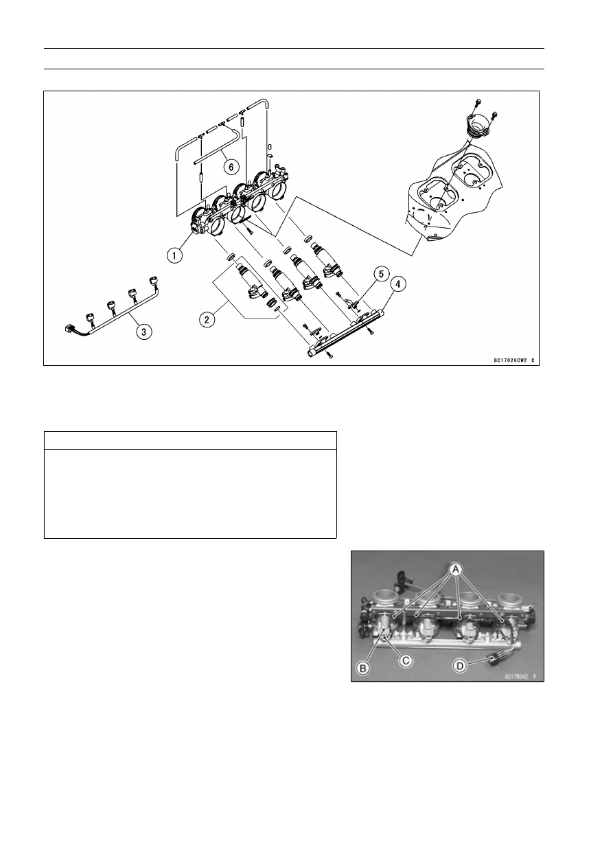
Throttle Body Assy Disassembly (ZX1200-B1/B2)

1. Throttle Body Assy
2. Injector
3. Injector Connector Assy
4. Delivery Pipe Assy

5. Nipple Assy
6. Inlet Air Pressure Sensor Hose

CAUTION

Do not remove, disassemble or adjust the throttle
sensor, throttle link mechanism and throttle body
assy, because they are adjust or set surely at the
manufacturer. Adjustment of these parts could re-
sult in poor performance, requiring replacement of
the throttle body assy.

Remove the throttle body assembly (see this chapter).

Open the clamps (4) [A] which bind the connector lead.

Pressing the tab [C] of each injector connector [B], pull
out the each connector and remove the injector connector
assy [D].

FUEL SYSTEM (DFI) 3-23

Throttle Body Assy

Pull out the each hose [A] from the throttle body fittings,
open the clamps (2) [B] which bind the hoses, and remove
the hose assy.

Remove the screws (2) [C] to pull out the injector assys
(4) from the throttle body assys together with the delivery
pipe [D].

NOTE

Do not damage the part of insert of the injectors when
they are pulled out from the throttle body.

Pull out the injector assy [A] from the delivery pipe [B].

NOTE

Do not damage the part of insert of the injectors when
they are pulled out from the delivery pipe.

Remove the nipple assy [C].

NOTE

Do not damage the part of insert of the nipple when it is
pulled out from the delivery pipe.

Throttle Body Assy Disassembly (ZX1200-B3

)

CAUTION

Do not remove, disassemble or adjust the main
throttle sensor [A], subthrottle sensor [B], sub-
throttle valve actuator [C], throttle link mechanism
[D] and throttle body assy [E], because they are
adjusted or set at the manufacturer. Adjustment
of these parts could result in poor performance,
requiring replacement of the throttle body assy.

Remove the throttle body assy (see Throttle Body Assy
Removal).

CAUTION

Never drop the throttle body assy, especially on a
hard surface. Such a shock to the body assy can
damage it.

Push the lock and disconnect the injector connectors [A].

Remove:

Screws [B]
Delivery Pipe [C] along with harness [D] and injectors

If necessary, cut straps and take the harness off the de-
livery pipe.

3-24 FUEL SYSTEM (DFI)

Throttle Body Assy

CAUTION

Never drop the injector, especially on a hard sur-
face. Such a shock to the injector can damage it.

Pull out the injectors along with the delivery pipe [A].
If necessary, remove the injectors from the delivery pipe.
Replace the O-rings of the indicators.
If necessary, cut straps and take the harness off the de-
livery pipe.

Throttle Body Assy Assembly (ZX1200-B1/B2)

Before assembling, blow away dirt or dust from the throttle
body and delivery pipe by applying compressed air.

Apply daphne oil or engine oil to the new O-rings [B] of
each injector [A], insert them to the delivery pipe assy [C]
and confirm whether the injectors turn smoothly or not.

NOTE

Replace the O-ring of injectors and the dust seals of
delivery pipe to new one.

Apply daphne oil or engine oil to the O-rings, insert the
and nipple assy [D] to the delivery pipe and tighten the
screws [E] after confirming the nipple assy turn smoothly.

Torque - Regulator and Nipple Assy Screws: 3.5 N·m (0.35

kgf·m, 31 in·lb)

Apply daphne oil or engine oil to the new dust seals [A],
insert the injectors installed to the delivery pipe assy to
the throttle body.

NOTE

Replace the dust seals of the throttle body to new one.

Install the delivery pipe assy to the throttle body.

Torque - Delivery Pipe Screws: 5.0 N·m (0.50 kgf·m, 44

in·lb)

Install the injector connectors to each injector, and bind
the connector lead with clamps (4).

NOTE

Keep the clearance of 5 mm (0.20 in.) or more between
the connector lead and the nipple assy when the con-
nector leads are run.

Run each connector lead keeping the clearance of 2

4 mm (0.08

0.16 in.) above each connector.

Insert the each hoses to the throttle body fittings, and bind
the hose assy with the clamps (2).

Install the throttle body assy (see Throttle Body Assy In-
stallation).

FUEL SYSTEM (DFI) 3-25

Throttle Body Assy

Throttle Body Assy Assembly (ZX1200-B3

)

Replace the O-rings [A] with the new ones.

Before assembling, blow away dirt or dust from the throttle
body and delivery pipe by applying compressed air.

Apply engine oil to the new O-rings of fuel pipe.

Install the fuel pipe [B] to the delivery pipes [C].

Replace the O-rings [A] of injectors and the seals [B] with
the new ones.

Apply engine oil to the new O-rings of each injector [C],
insert them into the delivery pipe [D] and confirm whether
the injectors turn smoothly or not.

Install the injectors along with the delivery pipe assy into
the throttle bodies [E].

Torque - Delivery Pipe Screws: 3.4 N·m (0.35 kgf·m, 30

in·lb)

Bind the leads with straps [A].

Insert the each hoses onto the throttle body fittings.

Install the throttle body assy (see Throttle Body Assy In-
stallation).

3-26 FUEL SYSTEM (DFI)

Air Line

Element Removal

Remove:

Seats (see Frame chapter)
Fuel Tank Cover (see Fuel Tank Removal)
Supporting Rod (see Fuel Tank Removal)

Set up the fuel tank [A] with the supporting rod [B].

CAUTION

Do not insert the supporting rod into the bolt hole,
or the thread of the bolt hole could be damaged.

Unscrew the nuts [A] and remove the bolts.

Pull out the elements [B].

Element Installation

Install the elements [A] with the mark side (FRONT) facing
front.

Air Cleaner Element Cleaning and Inspection

Refer to the Air Cleaner Element Cleaning (ZX1200
-B1/B2)/Element Replacement (ZX1200-B3

) in the

Periodic Maintenance chapter.

Oil Draining

A drain hose is connected to the bottom of the air cleaner

part to drain water or oil accumulated in the cleaner part.

Visually check the catch tank [A] of the drain hose if the
water or oil accumulates in tank.
If any water or oil accumulates in the tank, drain it by
taking off the drain plug [B] at the lower end of the drain
hose.

WARNING

Be sure reinstall the plug in the drain hose after
draining. Oil on tires will make them slippery and
can cause an accident and injury.

FUEL SYSTEM (DFI) 3-27

Air Line

Air Inlet Duct Removal

Remove the lower inner cover (see Frame chapter).

Loosen the clamp screws [A].

Slide the frame side of the duct forward first, and remove
the duct [B].

Air Inlet Duct Installation

The left rubber duct [A] has a L mark [B] and the right
rubber duct has a R mark.

First insert the duct to the front duct and then insert the
rubber duct stopped to the frame duct.

Tighten the clamp screws securely.

Front Duct Removal/Installation

Refer to the Upper Fairing Disassembly/Assembly in the
Frame chapter.

3-28 FUEL SYSTEM (DFI)

Fuel Tank

Fuel Tank Removal

WARNING

Gasoline is extremely flammable and can be explo-
sive under certain conditions. Make sure the area
is well-ventilated and free from any source of flame
or sparks; this includes any appliance with a pilot
light. Do not smoke. Turn the ignition switch OFF.
Be prepared for fuel spillage; any spilled fuel must
be completely wiped up immediately.

CAUTION

For California model, if gasoline, solvent, water or
any other liquid enters the canister, the canister’s
vapor absorbing capacity is greatly reduced. If the
canister does become contaminated, replace it with
a new one.

Remove:

Rear Seat (see Frame chapter)
Front Seat (see Frame chapter)
Allen Bolts [A]
Fuel Tank Cover Plate [B]

Screws [A]
Allen Bolts [B]
Fuel Tank Cover [C]

Bolt [A]

FUEL SYSTEM (DFI) 3-29

Fuel Tank

Pull up the front portion of the fuel tank, and then, pull out
the supporting rod [A].

Lift the front portion of the fuel tank [A] and support it with
the supporting rod [B].

CAUTION

Do not insert the supporting rod into the bolt hole,
or the thread of the bolt hole could be damaged.

Be sure to place a piece of cloth [A] around the fuel outlet
hose pipe [B] of the fuel tank.

Loosen the clamp bolt [C] and pull out the fuel supply hose
[D] from the pipe.

Quickly plug the pipe with a plug [E] (a suitable air cleaner
catch tank plug).

Drain the fuel in hose into a suitable container.

WARNING

Be prepared for fuel spillage; any spilled fuel must
be completely wiped up immediately.
When the fuel hose is disconnected, fuel spills out
from the hose and the pipe because of residual
pressure. Cover the hose connection with a piece
of clean cloth to prevent fuel spillage.

Disconnect the connectors [A].

CAUTION

Do not pull the leads [B] of the fuel pump and fuel
reserve switch.
If they are pulled, their lead terminals may be dam-
aged.

3-30 FUEL SYSTEM (DFI)

Fuel Tank

Remove the supporting rod, and set the fuel tank to proper
position.

Remove the breather hose [A] and return hose [B].

CAUTION

The fuel tank may be damaged if its bracket bolts
are removed lifting the front portion of fuel tank up-
ward.

Unscrew the bolts [C].

Remove the fuel tank.

Fuel Tank Installation

Installation is the fuel tank bracket bolts first, and then
install the other parts.

Be sure the hose is clamped securely to prevent leaks.

Torque - Fuel Hose Clamp Bolt: 1.5 N·m (0.15 kgf·m, 13

in·lb)

Route the hoses correctly.

Be sure to insert the drain hose [A] in the catch tank [B].

Fuel Tank Inspection

Remove the hose(s) from the fuel tank, and open the tank
cap.

Check to see if the water drain pipe [B] and fuel breather
pipe [C] in the tank are not clogged. Check the tank cap
breather also.
If they are clogged, remove the tank and drain it, and then
blow the breather free with compressed air.

CAUTION

Do not apply compressed air to the air vent holes
[A] in the tank cap. This could cause damage and
clogging of the labyrinth in the cap.

Visually inspect the fuel pump bracket [A] and fuel level
sensor [B] mounting portions for fuel leaks.
If they are fuel leaks, replace the gasket.

FUEL SYSTEM (DFI) 3-31

Fuel Tank

Fuel Tank Cleaning

WARNING

Clean the tank in a well-ventilated area, and take
care that there are no sparks or flame anywhere
near the working area. Because of the danger or
highly flammable liquids, do not use gasoline or low
flash point solvents to clean the tank.

Remove the fuel tank (see Fuel Tank Removal).

Drain the fuel.

Remove the fuel pump assy and fuel lever sensor.

Pour some high flash-point solvent into the fuel tank and
shake the tank to remove dirt and fuel deposits.

Pour the solvent over of the tank.

Dry the tank with compressed air.

Install the fuel pump assy (see Fuel Pump Installation)
and fuel level sensor (see Electrical System chapter) in
the tank.

Install the fuel tank (see Fuel Tank Installation).

3-32 FUEL SYSTEM (DFI)

DFI System

DFI System Wiring Diagram (ZX1200-B1/B2)

FUEL SYSTEM (DFI) 3-33

DFI System

Part Name

1. ECU (Electric Control Unit)
2. Gear Position Switch
3. Inlet Air Pressure Sensor
4. Throttle Sensor
5. Water Temperature Sensor
6. Camshaft Position Sensor
7. Crankshaft Sensor
8. Side Stand Switch
9. Injector #4

10. Injector #3

11. Injector #2

12. Injector #1
13. Stick Coil #1
14. Stick Coil #2
15. Stick Coil #3
16. Stick Coil #4
17. Ignition Switch
18. Starter Button
19. Engine Stop Switch
20. Tachometer
21. FI Indicator LED Light
22. Junction Box
23. Ignition Fuse 10 A
24. Starter Circuit Relay
25. ECU Main Relay
26. Fuel Pump Relay
27. ECU Main Fuse 15 A
28. Vehicle-down Sensor
29. Starter Motor
30. Starter Motor Relay
31. Main Fuse 30 A
32. Starter Lockout Switch
33. Battery 12 V 12 Ah
34. Fuel Pump
35. Self-diagnosis Indicator Switch
36. Open or Short Circuit Connector*

*Do not exchange the connector. To ensure optional ignition and fuel injection timing, the ECU
and connector are combined.

ECU and Connector Combinations

ECU Part No.

21175-1087

21175-1089

21175-1090

21175-1091

21175-1092

Open Connector

Short Circuit Connector

The part number of the ECU is in the label on the ECU.

37. Inlet Air Temperature Sensor
38. Atmospheric Pressure Sensor
39. Meter Assembly
40. Speed Sensor

3-34 FUEL SYSTEM (DFI)

DFI System

Terminal Numbers of ECU Connectors (ZX1200-B1/B2)

Terminal Names

1. Stick Coil #1 Output Signal
2. Stick Coil #2 Output Signal
3. Stick Coil #3 Output Signal
4. Injector #1 Output Signal
5. Injector #2 Output Signal
6. Injector #3 Output Signal
7. Injector #4 Output Signal
8. Fuel Pump Relay Output Signal
9. Speed Sensor (SIG)

10. Stick Coil #4 Output Signal

11. Unused

12. Unused
13. Unused
14. Unused
15. Input Signal for Memory
16. Input Signal for Memory
17. Power Supply to ECU
18. Injector Power Source Circuit Ground to Battery
19. Interlock Switch Output Signal
20. Detect the Neutral Position Signal
21. Switch Displaying Diagnosis
22. Engine Speed Signal to Tachometer
23. Detect Interlock Function for Engine Stops
24. Input Signal for Memory
25. Input Signal for Memory
26. Ignition System Circuit Ground to Battery
27. Injector Power Source Circuit Ground to Battery
28. Detect the Starter Button Pushed.
29. Unused
30. Unused
31. Unused
32. Detect the Engine Stop Switch OFF
33. FI Indicator LED Light Blinking
34. Input Signal for Memory

FUEL SYSTEM (DFI) 3-35

DFI System

35. ECU Power Source Circuit Ground to Battery
36. Crankshaft Sensor (+) Output Signal
37. Camshaft Position Sensor (+) Output Signal
38. Power Source for External Diagnosis System
39. Power Supply to ECU
40. Vehicle-down Sensor Output Signal
41. Power Source to Sensor System
42. Power Supply to Injector and Fuel Pump
43. Crankshaft Sensor (–) Output Signal
44. Camshaft Position Sensor (–) Output Signal
45. Atmospheric Pressure Sensor Output Signal
46. Detect the 4th Gear Position Signal
47. Detect the 1st Gear Position Signal
48. Power Source to ECU
49. Output Signal for External Diagnosis System
50. Unused
51. Inlet Air Pressure Sensor Output Signal
52. Detect the 5th Gear Position Signal
53. Detect the 2nd Gear Position Signal
54. Sensor System Circuit Ground from ECU
55. Ground for External Diagnosis System
56. Throttle Sensor Output Signal
57. Inlet Air Temperature Sensor Output Signal
58. Water Temperature Sensor Output Signal
59. Detect the 6th Gear Position Signal
60. Detect the 3rd Gear Position Signal

3-36 FUEL SYSTEM (DFI)

DFI System

DFI System Wiring Diagram (ZX1200-B3

)

FUEL SYSTEM (DFI) 3-37

DFI System

Part Name

1. ECU (Electric Control Unit)
2. Gear Position Switch
3. Inlet Air Pressure Sensor
4. Air Switching Valve
5. Water Temperature Sensor
6. Camshaft Position Sensor
7. Crankshaft Sensor
8. Side Stand Switch
9. Injector #1, #2, #3, #4

10. Subthrottle Valve Actuator

11. Subthrottle Sensor

12. Main Throttle Sensor
13. Stick Coil #1, #2, #3, #4
14. Atmospheric Pressure Sensor
15. Meter Assembly
16. Speed Sensor
17. Ignition Switch
18. Starter Button
19. Engine Stop Switch
20. Tachometer
21. FI Indicator LED Light
22. Junction Box
23. Ignition Fuse 10 A
24. Starter Circuit Relay
25. ECU Main Relay
26. Fuel Pump Relay
27. ECU Main Fuse 15 A
28. Vehicle-down Sensor
29. Inlet Air Temperature Sensor
30. Starter Relay
31. Main Fuse 30 A
32. Starter Lockout Switch
33. Battery 12 V 12 Ah
34. Fuel Pump
35. Self-diagnosis Terminal
36. Starter Motor

3-38 FUEL SYSTEM (DFI)

DFI System

Terminal Numbers of ECU Connectors (ZX1200-B3

)

1. Subthrottle Valve Actuator Drive Signal
2. Subthrottle Valve Actuator Drive Signal
3. Unused
4. Unused
5. Unused
6. Ignition Switch Signal
7. Main Throttle Sensor Signal
8. Inlet Air Pressure Sensor Signal
9. Water Temperature Sensor Signal (+)

10. Power Supply to Sensors

11. Speed Sensor Signal

12. Camshaft Position Sensor Signal (+)
13. Crankshaft Sensor Signal (+)
14. Immobilizer Communication Line
15. Immobilizer Communication Line
16. Battery Power ON-OFF Signal
17. Power Supply to ECU, Injectors, and Fuel Pump
18. Subthrottle Valve Actuator Drive Signal
19. Subthrottle Valve Actuator Drive Signal
20. Unused
21. Unused
22. Unused
23. Vehicle-down Sensor Signal
24. Subthrottle Sensor Signal
25. Atmospheric Pressure Sensor Signal
26. Inlet Air Temperature Sensor Signal (+)
27. Unused
28. Ground to Sensors
29. Camshaft Position Sensor Signal (–)
30. Crankshaft Sensor Signal (–)
31. Immobilizer Communication Line
32. External Diagnosis System Signal
33. Power Supply to Injector and Fuel Pump
34. ECU Power Source Circuit Ground to Battery (–) Terminal
35. Detect the 3rd Gear Position Signal

FUEL SYSTEM (DFI) 3-39

DFI System

36. Detect the 2nd Gear Position Signal
37. Detect the 1st Gear Position Signal
38. FI Indicator LED Light Signal
39. Tachometer Signal
40. Electric Starter Button Signal
41. Injector #4 Signal
42. Injector #3 Signal
43. Injector #2 Signal
44. Injector #1 Signal
45. Stick Coil #3 Signal
46. Stick Coil #2 Signal
47. Stick Coil #1 Signal
48. Detect the 6th Gear Position Signal
49. Detect the 5th Gear Position Signal
50. Detect the 4th Gear Position Signal
51. Self-diagnosis Signal (Generated by grounding this terminal and shown by FI indicator LED

light)

52. Engine Stop Switch Signal
53. Interlock Circuit Signal
54. Starter Lockout Switch Signal
55. Neutral Switch Signal
56. Fuel Pump Relay Signal
57. Air Switching Valve Signal
58. DFI System Ground
59. Ignition System Ground
60. Stick Coil #4 Signal

3-40 FUEL SYSTEM (DFI)

DFI Servicing Precautions

There are a number of important precautions that should

be followed servicing the DFI system.

This DFI system is designed to be used with a 12 V battery
as its power source. Do not use any other battery except
for a 12 V battery as a power source.

Do not reverse the battery cable connections. This will
damage the ECU.

To prevent damage to the DFI parts, do not disconnect the
battery cables or any other electrical connections when
the ignition SW (switch) is on, or while the engine is run-
ning.

Take care not to short the leads that are directly con-
nected to the battery positive (+) terminal to the chassis
ground.

When charging, remove the battery from the motorcycle.
This is to prevent ECU damage by excessive voltage.

Whenever the DFI electrical connections are to be discon-
nected, first turn off the ignition SW (switch). Conversely,
make sure that all the DFI electrical connections are firmly
reconnected before starting the engine.

Do not turn the ignition SW ON while any of the DFI elec-
trical connectors are disconnected. The ECU memorizes
service codes.

Do not spray water on the electrical parts, DFI parts, con-
nectors, leads, and wiring.

If a transceiver is installed on the motorcycle, make sure
that the operation of the DFI system is not influenced by
electric wave radiated from the antenna. Check operation
of the system with the engine at idle. Locate the antenna
as far as possible away from the ECU.

When any fuel hose is disconnected, do not turn on the
ignition SW. Otherwise, the fuel pump will operate and
fuel will spout from the fuel hose.

Do not operate the in-tank fuel pump if the pump is com-
pletely dry. This is to prevent pump seizure.

Before removing the fuel system parts, blow the outer sur-
faces of these parts clean with compressed air.

When any fuel hose is disconnected, fuel may spout out
by residual pressure in the fuel line. Cover the hose joint
with a piece of clean cloth to prevent fuel spillage.

When installing the fuel hoses, avoid sharp bending, kink-
ing, flattening or twisting, and route the fuel hoses with a
minimum of bending so that the fuel flow will not be ob-
structed.

Route the hoses according to Cable, Wire, and Hose
Routing section in the General Information chapter.

FUEL SYSTEM (DFI) 3-41

DFI Servicing Precautions

Install the hose clamps in the position shown, and se-
curely tighten the clamp bolts to the specified torque.
Check the fuel system for leaks after hose installation.

Fuel Hose [A]
Clamp [B]
Fuel Pipe [C]

Torque - Fuel Hose Clamp Bolts: 1.5 N·m (0.15 kgf·m, 13

in·lb)

To prevent corrosion and deposits in the fuel system, do
not add to fuel any fuel antifreeze chemicals.

Replace the fuel hose if it has been sharply bent or kinked.

The fuel hoses are designed to be used through out the
motorcycle’s life without any maintenance, however, if the
motorcycle is not properly handled, the high pressure in-
side the fuel line can cause fuel to leak [A] or the hose to
burst. Bend and twist the fuel hose while examining it.
Replace the hose if any cracks [B] or bulges [C] are no-
ticed.

To maintain the correct fuel/air mixture (F/A), there must
be no inlet air leaks in the DFI system. Be sure to install
the oil filler plug [A] after filling the engine oil.

Clutch Cover [B]

Torque - Oil Filler Plug: 1.5 N·m (0.15 kgf·m, 13 in·lb)

3-42 FUEL SYSTEM (DFI)

Troubleshooting the DFI System

Outline

When an abnormality in the system occurs, the FI indica-

tor LED (Light Emitting Diode) light goes on to alert the rider
on the meter panel. In addition, the condition of the problem
is stored in the memory of the ECU (electronic control unit).
With the engine stopped and turned in the self-diagnosis
mode, the service code [A] is indicated by the number of
times the FI indicator LED light blinks.

When due to a malfunction, the FI indicator LED light re-

mains lit, ask the rider about the conditions [B] under which
the problem occurred and try to determine the cause [C].
Don’t rely solely on the DFI self-diagnosis function, use
common sense; first conduct a pre-diagnosis inspection,
check the ECU for ground and power supply, the fuel line for
no fuel leaks, and for correct pressure. The pre-diagnosis
items are not indicated by the FI indicator LED light.

Even when the DFI system is operating normally, the FI

indicator LED light [A] may light up under strong electri-
cal interference. No remedy needed. Turn the ignition SW
(switch) OFF to stop the indicator light.

When the FI indicator LED light goes on and the motor-

cycle is brought in for repair, check the service codes.

When the repair has been done, the LED light doesn’t go

on. But the service codes stored in memory are not erased
to preserve the problem history, and the LED light can dis-
play the codes in the self-diagnosis mode. The problem
history is referred when solving unstable problems.

Much of the DFI system troubleshooting work consists

of confirming continuity of the wiring. The DFI parts are
assembled and adjusted with precision, and it is impossible
to disassemble or repair them.

When checking the DFI parts, use a digital meter which
can be read two decimal place voltage or resistance.

Remove:

Seats (see Frame chapter)
Strage Box (see Frame chapter)

The DFI part connectors have seals, including the ECU.
When measuring the input or output voltage with the
connector joined, use the needle adapter set. Insert the
needle adapter inside the seal until the needle adapter
reaches the terminal (for example, ECU is shown.).

Digital Meter [A]
Connector [B]
Needle Adapter Set [C]

Special Tool - Needle Adapter Set: 57001-1457

CAUTION

Tape the leads to prevent short circuit of the leads.

FUEL SYSTEM (DFI) 3-43

Troubleshooting the DFI System

After measurement, remove the needle adapters and ap-
ply silicone sealant to the seals [A] of the connector [B]
for waterproofing.

Silicone Sealant (Kawasaki Bond: 56019-120) - Seals
of Connector

Always check battery condition before replacing the DFI
parts. A fully charged battery is a must for conducting
accurate tests of the DFI system.

Trouble may involve one or in some cases all items.
Never replace a defective part without determining what
CAUSED the problem. If the problem was caused by
some other item or items, they too must be repaired or
replaced, or the new replacement part will soon fail again

Measure coil winding resistance when the DFI part is cold
(at room temperature)

Do not adjust or remove the throttle sensor.

Do not directly connect a 12 V battery to a fuel injector.
Insert a resistor (5

7

) or a bulb (12 V × 3

3.4 W) in

series between the battery and the injector.

The DFI parts have been adjusted and set with precision.
Therefore, they should be handled carefully, never strike
sharply, as with a hammer, or allowed to drop on a hard
surface. Such a shock to the parts can damage them.

Check wiring and connections from the ECU connector
to the suspected faulty DFI parts, using the hand tester
(special tool, analog tester) rather than a digital tester.

Special Tool - Hand Tester: 57001-1394

Make sure all connectors in the circuit are clean and tight,
and examine wires for signs of burning, fraying, etc. Dete-
riorated leads and bad connections can cause reappear-
ance of problems and unstable operation of the DFI sys-
tem.
If any wiring is deteriorated, replace the wiring.

3-44 FUEL SYSTEM (DFI)

Troubleshooting the DFI System

Pull each connector [A] apart and inspect it for corrosion,
dirt, and damage.
If the connector is corroded or dirty, clean it carefully. If it
is damaged, replace it. Connect the connectors securely.

Check the wiring for continuity.

Use the wiring diagram to find the ends of the lead which
is suspected of being a problem.

Connect the hand tester between the ends of the leads.

Set the tester to the × 1

range, and read the tester.

If the tester does not read 0

, the lead is defective. Re-

place the lead or the main harness or the sub harness.

If both ends of a harness [A] are far apart, ground [B] the
one end [C], using a jumper lead [D] and check the con-
tinuity between the end [E] and the ground [F]. This en-
ables to check a long harness for continuity. If the harness
is open, repair or replace the harness.

When checking a harness [A] for short circuit, open one
end [B] and check the continuity between the other end
[C] and ground [D]. If there is continuity, the harness has
a short circuit to ground, and it must be repaired or re-
placed.

FUEL SYSTEM (DFI) 3-45

Troubleshooting the DFI System

Narrow down suspicious locations by repeating the con-
tinuity tests from the ECU connectors.
If no abnormality is found in the wiring or connectors, the
DFI parts are the next likely suspects. Check the part,
starting with input and output voltages. However, there is
no way to check the ECU itself.
If an abnormality is found, replace the affected DFI part.
If no abnormality is found in the wiring, connectors, and
DFI parts, replace the ECU.

The diagnosis flow chart illustrates the above procedures.

After inspection, be sure to connect all the DFI electrical
connectors. Do not turn the ignition SW ON while the DFI
electrical connectors and ignition system connectors are
disconnected. Otherwise, the ECU memorizes service
codes as open circuit.

Lead Color Codes:

BK: Black

G: Green

P: Pink

BL: Blue

GY: Gray

PU: Purple

BR: Brown

LB: Light blue

R: Red

CH: Chocolate

LG: Light green

W: White

DG: Dark green

O: Orange

Y: Yellow

Electrical Connectors:

Female Connectors [A]

Male Connectors [B]

3-46 FUEL SYSTEM (DFI)

Troubleshooting the DFI System

DFI Diagnosis Flow Chart

Inquiries to Rider

Each rider reacts to problems in different ways, so it is important to confirm what kind of symptoms
the rider has encountered.

Try to find out exactly what problem occurred under exactly what conditions by asking the rider;
knowing this information may help you reproduce the problem.

The diagnosis sheet will help prevent you from overlooking any areas, and will help you decide if it
is a DFI system problem, or a general engine problem.

FUEL SYSTEM (DFI) 3-47

Troubleshooting the DFI System

Sample Diagnosis Sheet

Rider Name:

Registration No. (License Plate No.):

Year of Initial Registration:

Model:

Engine No.:

Frame No.:

Date Problem Occurred:

Mileage:

Environment when problem occurred.

Weather

fine,

cloudy,

rain,

snow,

always,

other:

Temperature

hot,

warm,

cold,

very cold,

always

Problem Frequency

chronic,

often,

once

Road

street,

highway,

mountain road (

uphill,

downhill),

bumpy,

pebble

Altitude

normal,

high (about 1 000 m or more)

Motorcycle conditions when problem occurred.

light up immediately after ignition SW ON, and goes off after 1

2

seconds (normal).

FI Indicator LED Light

lights blinks immediately after ignition SW ON, and stays on (DFI

problem)

lights up immediately after ignition SW ON, but goes off after about 10

seconds (DFI problem).

unlights (LED light, ECU or its wiring fault).

sometimes lights up (probably wiring fault).

starter motor not rotating.

Starting Difficulty

starter motor rotating but engine doesn’t turn over.

starter motor and engine don’t turn over.

no fuel flow (

no fuel in tank,

no fuel pump sound).

engine flooded (do not crank engine with throttle opened, which promotes

engine flooding).

no spark.

choke lever is not pulled fully when using the lever (pull it fully when

using).

other:

right after starting.

Engine Stalls

when opening throttle grip.

when closing throttle grip.

when moving off.

when stopping the motorcycle.

when cruising.

other:

choke lever pulled out fully (push it in fully).

very low choke speed.

very low idle speed,

very high idle speed,

rough idle speed.

Poor Running at Low
Speed

battery voltage is low (charge the battery).

spark plug loose (tighten it).

spark plug dirty, broken, or gap maladjusted (remedy it).

backfiring.

after firing.

3-48 FUEL SYSTEM (DFI)

Troubleshooting the DFI System

hesitation when acceleration.

engine oil viscosity too high.

brake dragging.

engine overheating.

clutch slipping.

other:

choke lever pulled out fully (push it in fully).

spark plug loose (tighten it).

spark plug dirty, broken, or gap maladjusted (remedy it).

spark plug incorrect (replace it).

knocking (fuel poor quality or incorrect,

use high-octane gasoline).

Poor Running or No
Power at High Speed

brake dragging.

clutch slipping.

engine overheating.

engine oil level too high.

engine oil viscosity too high.

other:

FUEL SYSTEM (DFI) 3-49

DFI System Troubleshooting Guide

DFI System Troubleshooting Guide

NOTE

This is not an exhaustive list, giving every possible cause for each problem listed. It is meant
simply as a rough guide to assist the troubleshooting for some of the more common difficulties.

The ECU may be involved in the DFI electrical and ignition system troubles. If these parts and
circuits checked out good, be sure to check the ECU for ground and power supply. If the ground
and power supply are checked good, replace the ECU.

Engine Doesn’t Start, Starting Difficulty

Symptoms or possible Causes

Actions (chapter)

Starter motor not rotating:

Ignition and engine stop switches not ON

Turn both switches ON.

Starter lockout switch or neutral switch trouble

Inspect (see chapter 16).

Starter motor trouble

Inspect (see chapter 16).

Battery voltage low

Inspect and charge (see chapter 16).

Starter relays not contacting or operating

Inspect the starter relay (see chapter 16).

Starter button not contacting

Inspect and replace (see chapter 16).

Starter system wiring open or shorted

Inspect the wiring (see chapter 16).

Ignition switch trouble

Inspect and replace (see chapter 16).

Engine stop switch trouble

Inspect and repair or replace (see chapter 16).

Main 30 A or ignition fuse blown

Inspect and replace (see chapter 16).

Starter motor rotating but engine doesn’t
turn over:

Starter clutch trouble

Inspect (see chapter 9).

Starter idle gear trouble

Inspect (see chapter 9).

Engine won’t turn over:

Valve seizure

Inspect and replace (see chapter 5).

Cylinder, piston seizure

Inspect and replace (see chapter 5).

Camshaft seizure

Inspect and replace (see chapter 5).

Connecting rod small end seizure

Inspect and replace (see chapter 9).

Connecting rod big end seizure

Inspect and replace (see chapter 9).

Crankshaft seizure

Inspect and replace (see chapter 9).

Transmission gear or bearing seizure

Inspect and replace (see chapter 9).

Balancer bearing seizure

Inspect and replace (see chapter 9).

No fuel flow:

No or little fuel in tank

Supply fuel (see Owner’s Manual).

Fuel pump not rotating

Inspect (see chapter 3).

Fuel injector trouble

Inspect and replace (see chapter 3).

Fuel tank air vent obstructed

Inspect and repair (see chapter 3).

Fuel filter or pump screen clogged

Inspect and replace fuel pump (see chapter 3).

Fuel pressure regulator clogged

Inspect and replace fuel pump (see chapter 3).

Fuel line clogged

Inspect and repair (see chapter 3).

Engine flooded:

Spark plug dirty, broken or gap maladjusted

Clean spark plugs and adjust plug gap (see
chapter 2).

3-50 FUEL SYSTEM (DFI)

DFI System Troubleshooting Guide

Symptoms or possible Causes

Actions (chapter)

Starting technique faulty

When flooded, don’t crank engine with throttle
fully opened.

No spark or spark weak:

Ignition and engine stop switches not ON

Turn both switches ON.

Clutch lever not pulled in and gear not in neutral
whether sidestand up or not

Pull the lever in and shift the gear in neutral.

Though clutch lever pulled in, sidestand up and
gear not in neutral

Sidestand down and clutch lever pulled in whether
gear in neutral or not

Vehicle-down sensor coming off

Reinstall (see chapter 3).

Vehicle-down sensor trouble

Inspect (see chapter 3).

ECU ground or power supply trouble

Inspect (see chapter 3).

Battery voltage low

Inspect and charge (see chapter 16).

Spark plug dirty, broken or gap maladjusted

Clean spark plug and adjust plug gap (see chapter
2).

Spark plug cap trouble

Inspect stick coil (see chapter 16).

Spark plug cap shorted or not in good contact

Reinstall or inspect stick coil (see chapter 16).

Spark plug incorrect

Replace it with the correct plug (see chapter 16).

IC igniter in ECU trouble

Inspect (see chapter 16).

Neutral, starter lockout or sidestand switch
trouble

Inspect each switch (see chapter 16).

Crankshaft sensor trouble

Inspect (see chapter 16).

Stick coil trouble

Inspect (see chapter 16).

Ignition switch shorted

Inspect and replace (see chapter 16).

Engine stop switch shorted

Inspect and repair or replace (see chapter 16).

Starter system wiring shorted or open

Inspect and repair or replace (see chapter 16).

Main 30 A or ignition fuse blown

Inspect and replace (see chapter 16).

Fuel/air mixture incorrect:

Air cleaner clogged, poorly sealed or missing

Clean or reinstall (see chapter 3).

Leak from oil filler cap, crankcase breather hose
or air cleaner drain hose

Inspect and repair or replace (see chapter 3).

Water or foreign matter in fuel

Change fuel. Inspect and clean fuel system (see
chapter 3).

Fuel pressure regulator trouble

Inspect fuel pressure and replace fuel pump (see
chapter 3).

Main throttle sensor trouble

Inspect (see chapter 3).

Fuel pressure may be low

Inspect (see chapter 3).

Fuel pump trouble

Inspect (see chapter 3).

Fuel injector trouble

Inspect (see chapter 3).

Inlet air pressure sensor trouble

Inspect (see chapter 3).

Atmospheric pressure sensor trouble

Inspect (see chapter 3).

Inlet air temperature sensor trouble

Inspect (see chapter 3).

Water temperature sensor trouble

Inspect (see chapter 3).

Crankshaft sensor trouble

Inspect (see chapter 3).

Compression low:

Spark plug loose

Reinstall (see chapter 16).

Cylinder head not sufficiently tightened down

Tighten (see chapter 5).

FUEL SYSTEM (DFI) 3-51

DFI System Troubleshooting Guide

Symptoms or possible Causes

Actions (chapter)

Cylinder, piston worn

Inspect and replace (see chapter 5).

Piston ring bad (worn, weak, broken or sticking) Inspect and replace (see chapter 5).
Piston ring/groove clearance excessive

Inspect and replace (see chapter 5).

Cylinder head gasket damaged

Replace (see chapter 5).

Cylinder head warped

Inspect and replace (see chapter 5).

No valve clearance

Adjust (see chapter 2).

Valve guide worn

Inspect and replace (see chapter 5).

Valve spring broken or weak

Inspect and replace (see chapter 5).

Valve not seating properly (valve bent, worn or
carbon accumulating on seating surface)

Inspect and repair or replace (see chapter 5).

Poor Running at Low Speed

Symptoms or Possible Causes

Actions (chapter)

Spark weak:

Battery voltage low

Inspect and charge (see chapter 16).

Spark plug dirty, broken or gap maladjusted

Clean spark plugs and adjust plug gap (see
chapter 2).

Spark plug cap trouble

Inspect the stick coil (see chapter 16).

Spark plug cap shorted or not in good contact

Reinstall or inspect stick coil (see chapter 16).

Spark plug incorrect

Replace it with the correct plug (see chapter 16).

IC igniter in ECU trouble

Inspect (see chapter 16).

Crankshaft sensor trouble

Inspect (see chapter 16).

Stick coil trouble

Inspect (see chapter 16).

Fuel/air mixture incorrect:

Little fuel in tank

Supply fuel (see Owner’s Manual).

Air cleaner clogged, poorly sealed, or missing

Clean element or inspect sealing (see chapter 3).

Air cleaner duct loose

Reinstall (see chapter 3).

Air cleaner O-ring damaged

Replace (see chapter 3).

Fuel tank air vent obstructed

Inspect and repair (see chapter 3).

Throttle body assy loose

Reinstall (see chapter 3).

Throttle body assy O-ring damage

Replace (see chapter 3).

Choke lever pulled

Push it (see chapter 3).

Fuel filer or pump screen clogged

Inspect and replace fuel pump (see chapter 3).

Fuel pressure regulator clogged

Inspect fuel pressure and replace fuel pump (see
chapter 3).

Fuel line clogged

Inspect and repair (see chapter 3).

Inlet air pressure sensor trouble

Inspect (see chapter 3).

Inlet air temperature sensor trouble

Inspect (see chapter 3).

Thermostat trouble

Inspect and replace (see chapter 4).

Unstable (rough) idling:

Fuel injector trouble

Inspect (see chapter 3).

Main throttle sensor trouble

Inspect (see chapter 3).

Crankshaft sensor trouble

Inspect (see chapter 3).

Throttle valves not synchronizing

Inspect (see chapter 2).

3-52 FUEL SYSTEM (DFI)

DFI System Troubleshooting Guide

Symptoms or Possible Causes

Actions (chapter)

Inlet air temperature sensor trouble

Inspect (see chapter 3).

Water temperature sensor trouble

Inspect (see chapter 3).

Atmospheric pressure sensor trouble

Inspect (see chapter 3).

Fuel pressure too low or too high

Inspect (see chapter 3).

Battery voltage low

Inspect and charge (see chapter 16).

Incorrect idle speed:

Water temperature sensor trouble

Inspect (see chapter 3).

Main throttle sensor trouble

Inspect (see chapter 3).

Engine stalls easily:

Fuel pump trouble

Inspect (see chapter 3).

Fuel injector trouble

Inspect (see chapter 3).

Main throttle sensor trouble

Inspect (see chapter 3).

Camshaft position sensor trouble

Inspect (see chapter 3).

Fuel pressure too low or too high

Inspect (see chapter 3).

Inlet air pressure sensor trouble

Inspect (see chapter 3).

Water temperature sensor trouble

Inspect (see chapter 3).

Inlet air temperature sensor trouble

Inspect (see chapter 3).

Fuel line clogged

Inspect and repair (see chapter 3).

Fuel pressure too low or too high

Inspect (see chapter 3).

Fuel pressure regulator trouble

Inspect fuel pressure and replace fuel pump (see
chapter 3).

Crankshaft sensor trouble

Inspect (see chapter 16).

Stick coil trouble

Inspect (see chapter 16).

Compression low:

Spark plug loose

Reinstall (see chapter 16).

Cylinder head not sufficiently tightened down

Tighten (see chapter 5).

No valve clearance

Adjust (see chapter 2).

Cylinder, piston worn

Inspect and replace (see chapter 5).

Piston ring bad (worn, weak, broken or sticking) Inspect and replace (see chapter 5).
Piston ring/groove clearance excessive

Inspect and replace (see chapter 5).

Cylinder head gasket damaged

Replace (see chapter 5).

Cylinder head warped

Inspect and replace (see chapter 5).

Valve guide worn or stem seal damaged

Inspect and replace (see chapter 5).

Valve spring broken or weak

Inspect and replace (see chapter 5).

Valve not seating properly (valve bent, worn or
carbon accumulating on seating surface)

Inspect and repair or replace (see chapter 5).

Camshaft cam worn

Inspect and replace (see chapter 5).

Hesitation:

Too low fuel pressure

Inspect (see chapter 3).

Clogged fuel line

Inspect and repair (see chapter 3).

Cracked or obstructed inlet air pressure sensor
hose

Inspect and repair or replace (see chapter 3).

Fuel pump trouble

Inspect (see chapter 3).

Fuel injector trouble

Inspect (see chapter 3).

Inlet air temperature sensor trouble

Inspect (see chapter 3).

FUEL SYSTEM (DFI) 3-53

DFI System Troubleshooting Guide

Symptoms or Possible Causes

Actions (chapter)

Main throttle sensor trouble

Inspect (see chapter 3).

Subthrottle sensor trouble

Inspect (see chapter 3).

Subthrottle valve actuator trouble

Inspect (see chapter 3).

Water temperature sensor trouble

Inspect (see chapter 3).

Atmospheric pressure sensor trouble

Inspect (see chapter 3).

Inlet air pressure sensor trouble

Inspect (see chapter 3).

Loose injector connectors

Remedy (see chapter 3).

Crankshaft sensor trouble

Inspect and repair or replace (see chapter 16).

Stick coil trouble

Inspect and repair or replace (see chapter 16).

Loose terminal of battery (–) lead or engine
ground lead

Inspect and repair (see chapter 16).

Delay of ignition timing

Inspect crankshaft sensor and IC igniter in ECU
(see chapter 16).

Poor acceleration:

Choke lever pulled

Push it (see chapter 3).

Too low fuel pressure

Inspect (see chapter 3).

Water or foreign matter in fuel

Change fuel. Inspect and clean fuel system (see
chapter 3).

Clogged fuel filter or pump screen

Inspect and replace fuel pump (see chapter 3).

Fuel pump trouble

Inspect (see chapter 3).

Fuel injector trouble

Inspect (see chapter 3).

Inlet air temperature sensor trouble

Inspect (see chapter 3).

Water temperature sensor trouble

Inspect (see chapter 3).

Atmospheric pressure sensor trouble

Inspect (see chapter 3).

Subthrottle sensor trouble

Inspect (see chapter 3).

Subthrottle valve actuator trouble

Inspect (see chapter 3).

Stick coil trouble

Inspect and replace (see chapter 16).

Engine oil level to high

Repair (see chapter 7).

Spark plug dirty, broken or gap maladjusted

Clean spark plugs and adjust plug gap (see
chapter 2).

Stumble:

Too low fuel pressure

Inspect (see chapter 3).

Fuel injector trouble

Inspect (see chapter 3).

Main throttle sensor malfunction

Inspect (see chapter 3).

Subthrottle sensor trouble

Inspect (see chapter 3).

Subthrottle valve actuator trouble

Inspect (see chapter 3).

Water temperature sensor trouble

Inspect (see chapter 3).

Inlet air pressure sensor trouble

Inspect (see chapter 3).

Surge:

Unstable fuel pressure

Fuel pressure regulator trouble (Inspect and
replace fuel pump) or kinked fuel line (Inspect and
repair fuel line) (see chapter 3).

Fuel injector trouble

Inspect (see chapter 3).

Water temperature sensor trouble

Inspect (see chapter 3).

Backfiring when deceleration:


Content      ..     3      4      5      6     ..