Toyota Tundra. Manual - part 1594


  Index      Toyota     Toyota Tundra (2007-2010 year) - Service and Repair Manual


Search            copyright infringement  


Content   ..  1592  1593  1594  1595   ..


Toyota Tundra. Manual - part 1594


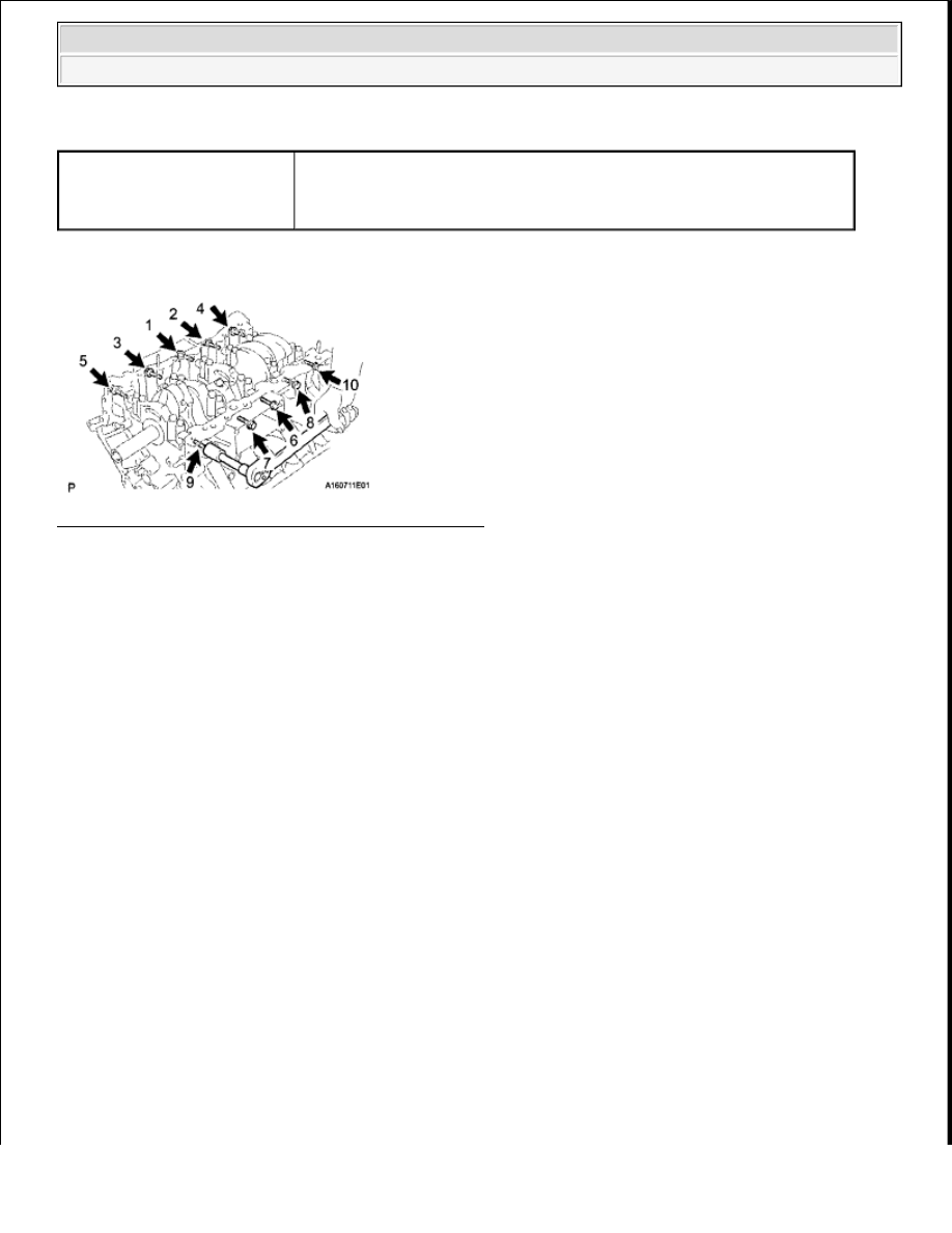
COMPONENT OPERATING RANGE 

WIRING DIAGRAM 

Fig. 213: Camshaft Position Sensor - Wiring Diagram 
Courtesy of TOYOTA MOTOR SALES, U.S.A., INC. 

INSPECTION PROCEDURE 

HINT  

Read freeze frame data using the Techstream. Freeze frame data records the engine conditions when 
malfunctions are detected. When troubleshooting, freeze frame data can help determine if the vehicle was 
running or stopped, if the engine was warmed up or not, if the air fuel ratio was lean or rich, and other data from 
the time the malfunction occurred. 

1. INSPECT CAMSHAFT POSITION SENSOR (SENSOR POWER SOURCE) 

a. Disconnect the D6 camshaft position sensor connector. 

Camshaft position sensor 
signal

Camshaft position sensor voltage fluctuates when the camshaft 
rotates  

3 signals per revolution of crankshaft  


2009 Toyota Tundra 

2009 ENGINE PERFORMANCE Engine Control System (3UR-FBE) - Tundra


Fig. 214: Identifying D6 Camshaft Position Sensor Connector Terminals 
Courtesy of TOYOTA MOTOR SALES, U.S.A., INC. 

b. Turn the ignition switch to ON.  

c. Measure the voltage according to the value (s) in the table below. 

Standard voltage  

VOLTAGE SPECIFIED CONDITION 

NG: REPAIR OR REPLACE HARNESS OR CONNECTOR  

OK: Go to Next Step  

2. CHECK HARNESS AND CONNECTOR (ECM - CAMSHAFT POSITION SENSOR) 

a. Disconnect the D6 camshaft position sensor connector. 

Tester Connection

Switch Condition Specified Condition

D6-3 (VC) - Body ground Ignition switch ON

4.5 to 5.0 V


2009 Toyota Tundra 

2009 ENGINE PERFORMANCE Engine Control System (3UR-FBE) - Tundra


Fig. 215: Identifying D6 Camshaft Position Sensor And D74 ECM Connector Terminals 
Courtesy of TOYOTA MOTOR SALES, U.S.A., INC. 

b. Disconnect the D74 ECM connector.  

c. Measure the resistance according to the value (s) in the table below. 

Standard resistance  

RESISTANCE SPECIFIED CONDITIONS 

NG: REPAIR OR REPLACE HARNESS OR CONNECTOR  

OK: Go to Next Step  

3. INSPECT SENSOR INSTALLATION 

a. Check the camshaft position sensor installation. 

OK:  

The camshaft position sensor is installed properly.  

NG: SECURELY REINSTALL SENSOR (See INSTALLATION ) 

Tester Connection

Condition Specified Condition

D6-1 (G2) - D74-90 (G2)

Always

Below 1 ohms

D6-2 (G-) - D74-89 (G2-)

Always

Below 1 ohms

D6-1 (G2) or D74-90 (G2) - Body ground

Always

10 kohms or higher

D6-2 (G-) or D74-89 (G2-) - Body ground Always

10 kohms or higher


2009 Toyota Tundra 

2009 ENGINE PERFORMANCE Engine Control System (3UR-FBE) - Tundra


Fig. 216: Identifying Camshaft Position Sensor Proper Installation Position 
Courtesy of TOYOTA MOTOR SALES, U.S.A., INC. 

OK: Go to Next Step  

4. INSPECT CAMSHAFT TIMING PLATE (SIGNAL PLATE TOOTH) 

a. Check the teeth of the signal plate. 

OK:  

Sensor plate teeth do not have any cracks or deformation.  

NG: REPLACE CAMSHAFT TIMING PLATE (See DISASSEMBLY ) 

OK: Go to Next Step  

5. REPLACE CAMSHAFT POSITION SENSOR 

a. Replace the camshaft position sensor (see INSTALLATION ).  

6. CONFIRM WHETHER DTC OUTPUT RECURS 

a. Connect the Techstream to the DLC3.  

b. Turn the ignition switch to ON.  

c. Turn the Techstream ON.  

d. Clear DTCs (see DTC CHECK/CLEAR ).  

e. Start the engine.  


2009 Toyota Tundra 

2009 ENGINE PERFORMANCE Engine Control System (3UR-FBE) - Tundra


Content   ..  1592  1593  1594  1595   ..