Content .. 1593 1594 1595 1596 ..
Toyota Tundra. Manual - part 1595
f. Enter the following menus Powertrain/Engine and ECT/Trouble Codes/Pending.
g. Read DTCs.
Result
DTC OUTPUT RESULT
HINT
If the engine does not start, replace the ECM.
B: REPLACE ECM (See REMOVAL )
A: END
DTC P1607 CRUISE CONTROL INPUT PROCESSOR
DESCRIPTION
The ECM continuously monitors its main and sub CPUs. This self-check ensures that the ECM is functioning
properly. If outputs from the CPUs are different and deviate from the standard, the ECM will illuminate the
MIL and store a DTC immediately.
DTC DETECTION CONDITION AND TROUBLE AREA REFERENCE CHART
MONITOR STRATEGY
MONITOR STRATEGY
TYPICAL ENABLING CONDITIONS
TYPICAL ENABLING CONDITIONS
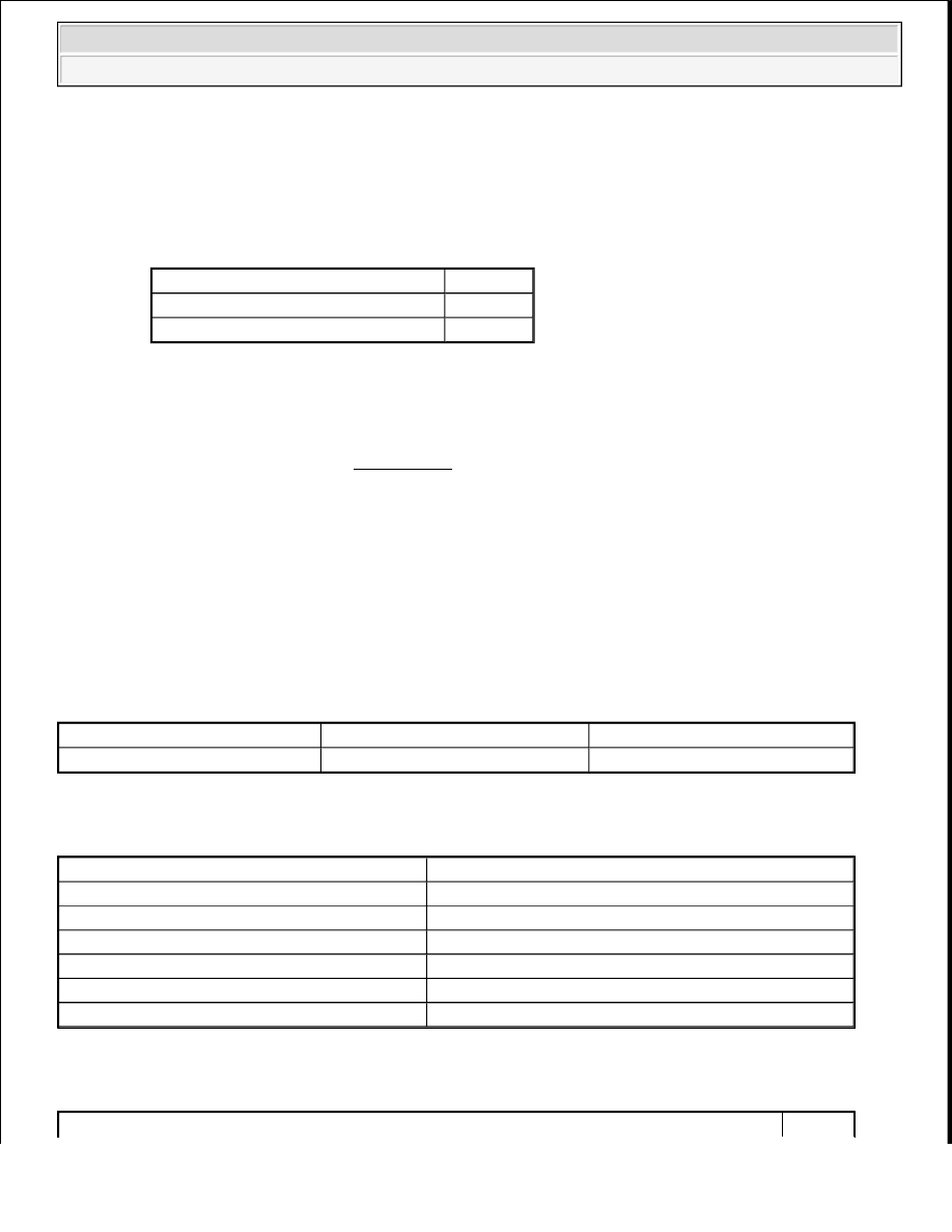
Result
Proceed to
No DTC is output
A
P1340, P1342 and/or P1343 are output
B
DTC
DTC Detection Condition
Trouble Area
P1607
ECM CPUs malfunction
ECM
Related DTC
P1607 Internal control module range check
Required sensors/Components (main)
ECM
Required sensors/Components (sub)
Cruise control
Frequency of Operation
Continuous
Duration
0.3 seconds
MIL Operation
Immediate
Sequence of Operation
None
2009 Toyota Tundra
2009 ENGINE PERFORMANCE Engine Control System (3UR-FBE) - Tundra