Iveco Stralis AT/AD. Manual - part 335
001014t
000847t
000044t
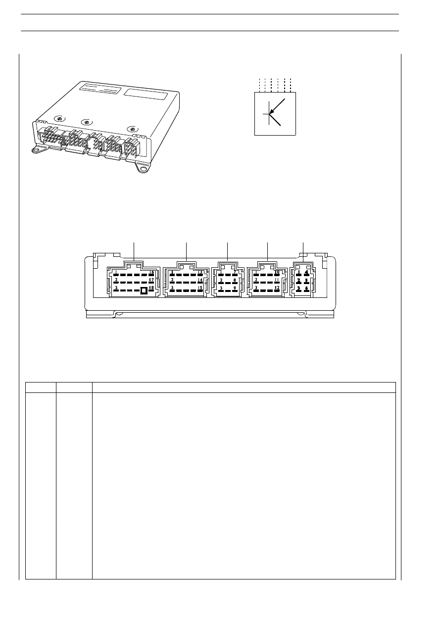
Connector X1
X1
X2
X3
X4
X5
III.124
ELECTRONIC SYSTEMS
S
TRALIS
AT/AD
Base - January 2003
Pin
Cable
Function
1
GN/VE
CAN line “L”
2
---
---
3
WS/BI
CAN line “H”
4
---
---
5
---
---
6
0048
Negative from ASR switch
7
8847
Power positive under key
8
7710
Power positive direct from battery
9
7720
Power positive direct from battery
10
---
---
11
0000
Mass
12
0000
Mass
13
2299
K line for diagnosis connector (pin 4)
14
---
---
15
---
Safety bridge pin 12 / 18
16
6672
---
17
---
---
18
---
---